Endress+Hauser Waterpilot FMX21 User manual

Products Solutions Services
Operating Instructions
Waterpilot FMX21
Hydrostatic level measurement
HART
BA00380P/00/EN/15.15
71293257
Valid as of version
01.00.zz

Waterpilot FMX21
2 Endress+Hauser
TAG No.: XXX000
Ser. No.: X000X000000
Order code 00X00-XXXX0XX0XXX
www.endress.com/deviceviewer Endress+Hauser Operations App
Serial number
A0023555
• Make sure the document is stored in a safe place such that it is always available when
working on or with the device.
• To avoid danger to individuals or the facility, read the "Basic safety instructions" section
carefully, as well as all other safety instructions in the document that are specific to
working procedures.
• The manufacturer reserves the right to modify technical data without prior notice. Your
Endress+Hauser distributor will supply you with current information and updates to
these Instructions.

Waterpilot FMX21 Table of contents
Endress+Hauser 3
Table of contents
1 Document information .............. 5
1.1 Document function ..................... 5
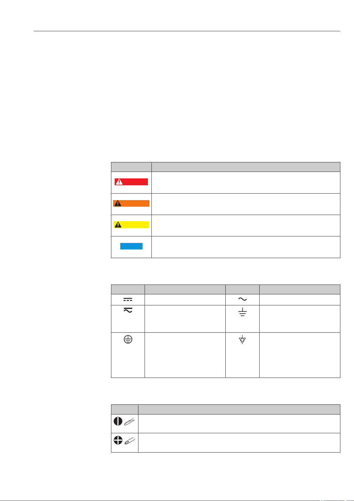
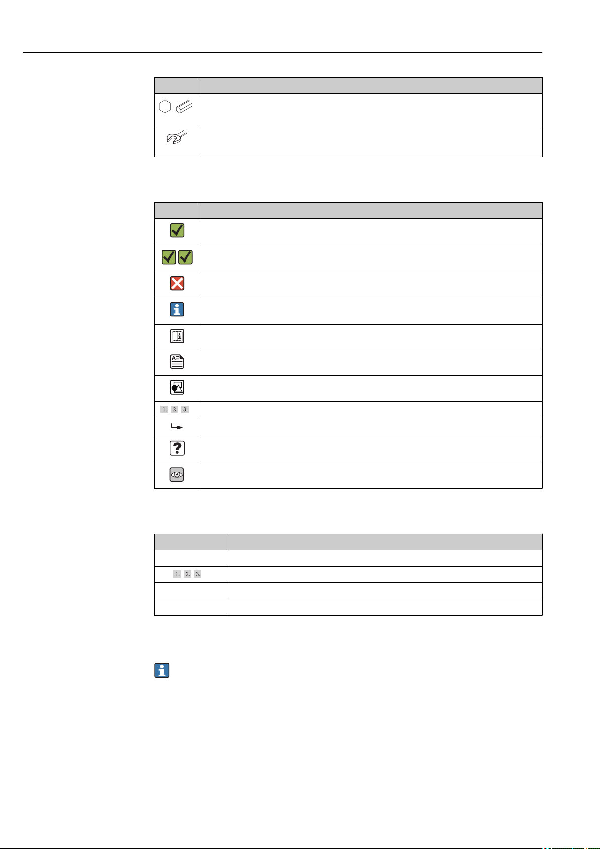
1.2 Symbols used .......................... 5
1.3 Documentation ........................ 6
1.4 Terms and abbreviations ................. 7
2 Basic safety instructions ............ 8
2.1 Requirements concerning the staff .......... 8
2.2 Designated use ........................ 8
2.3 Workplace safety ....................... 8
2.4 Operational safety ...................... 8
2.5 Product safety ......................... 9
3 Product description ................ 10
3.1 Function ............................ 10
4 Incoming acceptance and product
identification ..................... 11
4.1 Incoming acceptance ................... 11
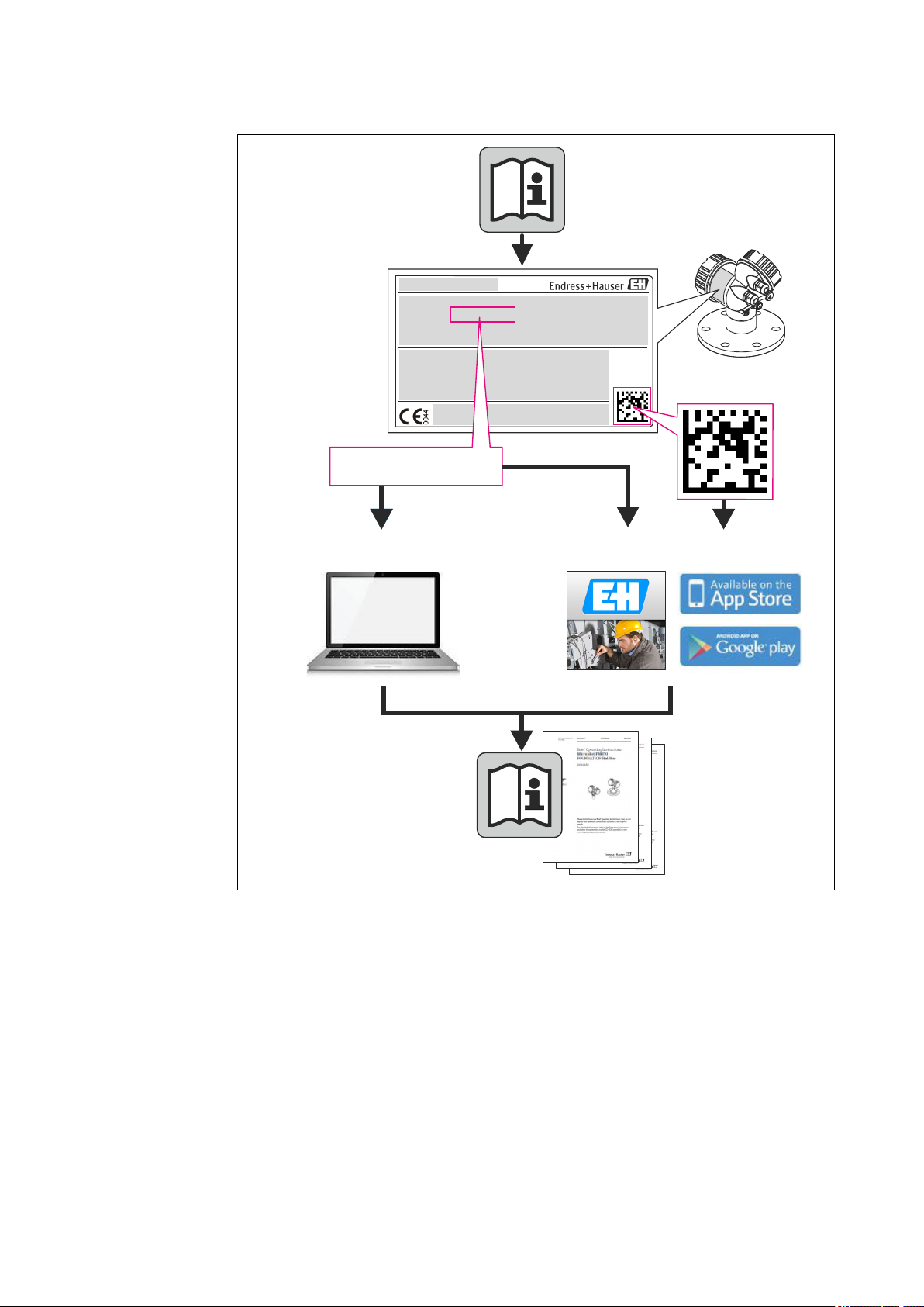
4.2 Product identification ................... 12
4.3 Nameplates .......................... 13
4.4 Identification of sensor type .............. 14
4.5 Storage and transport .................. 14
4.6 Scope of delivery ...................... 14
5 Installation ....................... 16
5.1 Installation conditions .................. 16
5.2 Additional mounting instructions .......... 17
5.3 Dimensions .......................... 17
5.4 Mounting the Waterpilot with a mounting
clamp .............................. 18
5.5 Mounting the Waterpilot with a cable
mounting screw ....................... 19
5.6 Mounting the terminal box .............. 20
5.7 Mounting the TMT182 temperature head
transmitter with terminal box ............ 20
5.8 Mounting the terminal strip for the Pt100
passive (without TMT182) ............... 21
5.9 Post-installation check .................. 21
6 Electrical connection .............. 23
6.1 Connecting the device .................. 23
6.2 Supply voltage ........................ 25
6.3 Cable specifications .................... 25
6.4 Power consumption .................... 25
6.5 Current consumption ................... 26
6.6 Maximum load ....................... 26
6.7 Connecting the measuring unit ........... 27
6.8 Post-connection check .................. 31
7 Operation options ................. 32
7.1 Overview of operating options ............ 32
7.2 Operating concept ..................... 33
7.3 Structure of the operating menu ........... 33
7.4 Locking/unlocking operation ............. 34
7.5 Resetting to factory settings (reset) ........ 35
8Integrating device via HART®
protocol .......................... 36
8.1 HART process variables and measured
values .............................. 36
8.2 Device variables and measured values ....... 37
9 Commissioning .................... 38
9.1 Post-installation check and function check ... 38
9.2 Unlocking/locking configuration .......... 38
9.3 Commissioning ....................... 38
9.4 Selecting the language .................. 39
9.5 Measuring mode selection ............... 39
9.6 For selecting the pressure engineering unit ... 40
9.7 Position adjustment .................... 40
9.8 Configuring the damping ................ 41
9.9 Configuring pressure measurement ........ 41
9.10 Configuring level measurement ........... 43
9.11 Automatic density compensation .......... 56
9.12 Linearization ......................... 59
9.13 Manual entry of a linearization table via
operating tool ........................ 62
9.14 Backing up or duplicating the device data .... 63
10 Diagnostics and troubleshooting ... 64
10.1 Troubleshooting ...................... 64
10.2 Diagnostic events ...................... 64
10.3 Troubleshooting specific to Waterpilot
FMX21 with optional Pt100 .............. 67
10.4 Troubleshooting specific to TMT182
temperature head transmitter ............ 68
10.5 Response of output to errors .............. 68
10.6 Firmware history ...................... 69
11 Maintenance ...................... 70
11.1 Exterior cleaning ...................... 70
12 Repairs ........................... 71
12.1 General notes ........................ 71
12.2 Spare parts .......................... 71
12.3 Return .............................. 71
12.4 Disposal ............................ 71

Table of contents Waterpilot FMX21
4 Endress+Hauser
13 Overview of the operating menu .... 72
13.1 Overview of parameters in the "Expert"
menu .............................. 75
14 Description of device parameters ... 80
14.1 Expert → System ...................... 80
14.2 Expert → System → Instrument info ........ 81
14.3 Expert → System → Management .......... 83
14.4 Expert → Measurement → Measuring mode .. 83
14.5 Expert → Measurement → Basic setup ....... 84
14.6 Expert → Measurement → Pressure ........ 86
14.7 Expert → Measurement → Level ........... 88
14.8 Expert → Measurement → Linearization ..... 93
14.9 Expert → Measurement → Sensor limits ..... 96
14.10 Expert → Measurement → Sensor trim ...... 97
14.11 Expert → Output → Current output ......... 98
14.12 Expert→ Communication → HART config. ... 102
14.13 Expert→ Communication → HART info ..... 104
14.14 Expert→ Communication → HART output ... 106
14.15 Expert→ Communication → HART input .... 109
14.16 Expert → Application .................. 111
14.17 Expert → Diagnosis ................... 112
14.18 Expert → Diagnosis → Diagnostic list ....... 114
14.19 Expert → Diagnosis→ Event logbook ....... 115
14.20 Expert → Diagnosis → Simulation ......... 116
15 Accessories ...................... 118
15.1 Suspension clamp .................... 118
15.2 Terminal box ........................ 118
15.3 Additional weight .................... 118
15.4 Temperature head transmitter TMT182 (4 to
20 mA HART) ....................... 119
15.5 Pt-100 resistance thermometer .......... 119
15.6 Cable mounting screws ................ 119
15.7 Terminals .......................... 119
15.8 Cable shortening kit ................... 119
15.9 Cable marking ....................... 119
15.10 Testing adapter ...................... 120
16 Technical data ................... 122
16.1 Input .............................. 122
16.2 Output ............................ 124
16.3 Performance characteristics ............. 127
16.4 Environment ........................ 129
16.5 Process ............................ 131
16.6 Additional technical data ............... 131
Index ................................. 132

Waterpilot FMX21 Document information
Endress+Hauser 5
1 Document information
1.1 Document function
These Operating Instructions contain all the information that is required in various phases
of the life cycle of the device: from product identification, incoming acceptance and
storage, to mounting, connection, operation and commissioning through to
troubleshooting, maintenance and disposal.
1.2 Symbols used
1.2.1 Safety symbols
Symbol Meaning
DANGER
DANGER!
This symbol alerts you to a dangerous situation. Failure to avoid this situation will result in
serious or fatal injury.
WARNING
WARNING!
This symbol alerts you to a dangerous situation. Failure to avoid this situation can result in
serious or fatal injury.
CAUTION
CAUTION!
This symbol alerts you to a dangerous situation. Failure to avoid this situation can result in
minor or medium injury.
NOTICE
NOTE!
This symbol contains information on procedures and other facts which do not result in
personal injury.
1.2.2 Electrical symbols
Symbol Meaning Symbol Meaning
Direct current Alternating current
Direct current and alternating current Ground connection
A grounded terminal which, as far as
the operator is concerned, is
grounded via a grounding system.
Protective ground connection
A terminal which must be connected
to ground prior to establishing any
other connections.
Equipotential connection
A connection that has to be connected
to the plant grounding system: This
may be a potential equalization line
or a star grounding system depending
on national or company codes of
practice.
1.2.3 Tool symbols
Symbol Meaning
A0011220
Flat blade screwdriver
A0011219
Philips screwdriver

Document information Waterpilot FMX21
6 Endress+Hauser
Symbol Meaning
A0011221
Allen key
A0011222
Open-ended wrench
1.2.4 Symbols for certain types of information
Symbol Meaning
Permitted
Procedures, processes or actions that are permitted.
Preferred
Procedures, processes or actions that are preferred.
Forbidden
Procedures, processes or actions that are forbidden.
Tip
Indicates additional information.
Reference to documentation
Reference to page
Reference to graphic
,…
,
Series of steps
Result of a step
Help in the event of a problem
Visual inspection
1.2.5 Symbols in graphics
Symbol Meaning
1, 2, 3 ... Item numbers
,…
,
Series of steps
A, B, C, ... Views
A-A, B-B, C-C, ... Sections
1.3 Documentation
The document types listed are available:
In the Downloads area of the Endress+Hauser website: www.endress.com →
Downloads
1.3.1 Technical Information (TI): planning aid for your device
TI00431P:
The document contains all the technical data on the device and provides an overview of
the accessories and other products that can be ordered for the device.

Waterpilot FMX21 Document information
Endress+Hauser 7
1.3.2 Brief Operating Instructions (KA): getting the 1st measured
value quickly
KA01189P:
The Brief Operating Instructions contain all the essential information from incoming
acceptance to initial commissioning.
1.3.3 Safety Instructions (XA)
Depending on the approval, the following Safety Instructions (XA) are supplied with the
device. They are an integral part of the Operating Instructions.
Directive Type of protection Category Documentation Option 1)
ATEX Ex ia IIC II 2 G XA00454P BD
ATEX Ex nA IIC II 3 G XA00485P BE
IECEx Ex ia IIC n/a XA00455P IC
CSA C/US Ex ia IIC n/a ZD00232P
(960008976)
CE
FM AEx ia IIC n/a ZD00231P
(960008975)
FE
NEPSI Ex ia IIC n/a XA00456P NA
INMETRO Ex ia IIC n/a XA01066P MA
1) Product Configurator order code for "Approval"
The nameplate indicates the Safety Instructions (XA) that are relevant to the device.
1.4 Terms and abbreviations
Term/abbreviation Explanation
XA Document type "Safety Instructions"
KA Document type "Brief Operating Instructions"
BA Document type "Operating Instructions"
SD Document type "Special Documentation"
TD Turn down
Set span and zero-based span.

Basic safety instructions Waterpilot FMX21
8 Endress+Hauser
2 Basic safety instructions
2.1 Requirements concerning the staff
The personnel for installation, commissioning, diagnostics and maintenance must fulfill
the following requirements:
‣Trained, qualified specialists: must have a relevant qualification for this specific
function and task
‣Are authorized by the plant owner/operator
‣Are familiar with federal/national regulations
‣Before beginning work, the specialist staff must have read and understood the
instructions in the Operating Instructions and supplementary documentation as well as
in the certificates (depending on the application)
‣Following instructions and basic conditions
The operating personnel must fulfill the following requirements:
‣Being instructed and authorized according to the requirements of the task by the
facility's owner-operator
‣Following the instructions in these Operating Instructions
2.2 Designated use
2.2.1 Application and media
The Waterpilot FMX21 is a hydrostatic pressure sensor for measuring the level of fresh
water, wastewater and salt water. The temperature is measured simultaneously in the case
of sensor versions with a Pt100 resistance thermometer. An optional temperature head
transmitter converts the Pt100 signal to a 4 to 20 mA signal with superimposed digital
communication protocol HART 6.0.
2.2.2 Incorrect use
The manufacturer is not liable for damage caused by improper or non-designated use.
Verification for borderline cases:
‣For special fluids and fluids for cleaning, Endress+Hauser is glad to provide assistance
in verifying the corrosion resistance of fluid-wetted materials, but does not accept any
warranty or liability.
2.3 Workplace safety
For work on and with the device:
‣Wear the required personal protective equipment according to federal/national
regulations.
‣Switch off the supply voltage before connecting the device.
2.4 Operational safety
Risk of injury!
‣Operate the device in proper technical condition and fail-safe condition only.
‣The operator is responsible for interference-free operation of the device.

Waterpilot FMX21 Basic safety instructions
Endress+Hauser 9
Modifications to the device
Unauthorized modifications to the device are not permitted and can lead to unforeseeable
dangers.
‣If, despite this, modifications are required, consult with Endress+Hauser.
Repairs
To ensure continued operational safety and reliability,
‣Carry out repairs on the device only if they are expressly permitted.
‣Observe federal/national regulations pertaining to repair of an electrical device.
‣Use original spare parts and accessories from Endress+Hauser only.
Hazardous area
To eliminate danger to persons or the facility when the device is used in the approval-
related area (e.g. explosion protection, pressure vessel safety):
‣Check the nameplate to verify if the device ordered can be put to its intended use in the
approval-related area.
‣Observe the specifications in the separate supplementary documentation that is an
integral part of these Instructions.
2.5 Product safety
This measuring device is designed in accordance with good engineering practice to meet
state-of-the-art safety requirements, has been tested, and left the factory in a condition in
which it is safe to operate.
It meets general safety standards and legal requirements. It also complies with the EC
directives listed in the device-specific EC Declaration of Conformity. Endress+Hauser
confirms this by affixing the CE mark to the device.

Product description Waterpilot FMX21
10 Endress+Hauser
3 Product description
3.1 Function
The ceramic measuring cell is a dry measuring cell i.e. the pressure acts directly on the
robust, ceramic process isolating diaphragm of the Waterpilot FMX21. Potential changes
in air pressure are guided via a pressure compensation tube through the extension cable to
the rear of the ceramic process isolating diaphragm and are compensated for. A pressure-
dependent change in capacitance, caused by the movement of the process isolating
diaphragm, is measured at the electrodes of the ceramic carrier. The electronics unit then
converts this to a signal that is proportional to the pressure and linear to the level.
h
2
1
patm
phydr.
p = p + p
atm hydr.
patm
patm
h ~ p
r•g
h = p
Rel.: p =
sens (p + p ) - p
atm hydr. atm
p = p + p
atm hydr.
Abs.: p =
sens (p + p )
atm hydr.
A0019140
1 Ceramic measuring cell
2 Pressure compensation tube
h Height level
p Total pressure = atmospheric pressure + hydrostatic pressure
ρ Density of the medium
g Acceleration due to gravity
Phydr. Hydrostatic pressure
Patm Atmospheric pressure
Psens Pressure displayed on the sensor

Waterpilot FMX21 Incoming acceptance and product identification
Endress+Hauser 11
4 Incoming acceptance and product
identification
4.1 Incoming acceptance
A0015502
DELIVERY NOTE
1 = 2
A0016870
Is the order code on the delivery note (1) identical to the order code on
the product sticker (2)?
A0026535
A0015502
A0026536
Are the goods undamaged?
A0015502
Dat./Insp.:
FW.Ver.:
Dev.Rev.:
Cal./Adj.
Mat: L=
Ser.no.:
Ordercode:
Ext.ordercode:
TAG:
WaterpilotFMX21
MadeinGermany,D-79689 Maulburg
p
DELIVERY NOTE
Dat./Insp.:
FW.Ver.:
Dev.Rev.:
Cal./Adj.
Mat: L=
Ser. no.:
Order code:
Ext. order code:
TAG:
Waterpilot FMX21
Made in Germany,D-79689 Maulburg
p
A0026537
Do the data on the nameplate correspond to the order specifications and
the delivery note?

Incoming acceptance and product identification Waterpilot FMX21
12 Endress+Hauser
A0015502
A0022106
Is the documentation available?
If required (see nameplate): Are the safety instructions (XA) present?
If one of these conditions does not apply, please contact your
Endress+Hauser sales office.
4.2 Product identification
The following options are available for identification of the measuring device:
• Nameplate specifications
• Order code with breakdown of the device features on the delivery note
• Enter serial numbers from nameplates in W@M Device Viewer
(www.endress.com/deviceviewer): All information about the measuring device is
displayed.
For an overview of the technical documentation provided, enter the serial number from
the nameplates in the W@M Device Viewer (www.endress.com/deviceviewer)

Waterpilot FMX21 Incoming acceptance and product identification
Endress+Hauser 13
4.3 Nameplates
4.3.1 Nameplates on extension cable
Dat./Insp.:
FW.Ver.:
Dev.Rev.:
Cal./Adj.
Mat: L=
Ser. no.:
Order code:
Ext. order code:
TAG:
Waterpilot FMX21
Made in Germany, D-79689 Maulburg
p
12
17
16
15
14
3 4
5
6/7
89
101112
13
A0018802
1 Order code (shortened for reordering); The meaning of the individual letters and digits is explained in the
order confirmation details.
2 Extended order number (complete)
3 Serial number (for clear identification)
4 TAG (device tag)
5 FMX21 connection diagram
6 Pt100 connection diagram (optional)
7 Warning (hazardous area), (optional)
8 Length of extension cable
9 Approval symbol, e.g. CSA, FM, ATEX (optional)
10 Text for approval (optional)
11 Materials in contact with process
12 Test date (optional)
13 Software version/device version
14 Supply voltage
15 Output signal
16 Set measuring range
17 Nominal measuring range
Additional nameplate for devices with approvals
Mat.: 316L/1.4435/1.4404, Al O , PE, EPDM, PPO
2 3 For use in drinking water according to:
Made in Germany, D-79689 Maulburg
Waterpilot FMX21
250002737-B
1
23
A0018805
1 Approval symbol (drinking water approval)
2 Reference to associated documentation
3 Approval number (marine approval)

Incoming acceptance and product identification Waterpilot FMX21
14 Endress+Hauser
4.3.2 Additional nameplate for devices with external diameter
22 mm (0.87 in) and 42 mm (1.65 in)
x
Install per dwg. 96000xxxx-
Ser.-No.:
p
Waterpilot FMX21
Cal./Adj.
1 2 3 4 5 6 7
A0018804
1 Serial number
2 Nominal measuring range
3 Set measuring range
4 CE mark or approval symbol
5 Certificate number (optional)
6 Text for approval (optional)
7 Reference to documentation
4.4 Identification of sensor type
With relative pressure or absolute pressure sensors, the "Pos.zero adjust" parameter is
displayed in the operating menu. With absolute pressure sensors, the "Calib. offset"
parameter is displayed in the operating menu.
4.5 Storage and transport
4.5.1 Storage conditions
Use original packaging.
Store the measuring device in clean and dry conditions and protect from damage caused by
shocks (EN 837-2).
Storage temperature range
• FMX21: –40 to +80 °C (–40 to +176 °F)
• TMT182: –40 to +100 °C (–40 to +212 °F)
• Terminal box: –40 to +80 °C (–40 to +176 °F)
4.5.2 Transporting the product to the measuring point
LWARNING
Incorrect transport!
Device or cable may become damaged, and there is a risk of injury!
‣Transport measuring device in the original packaging.
‣Follow the safety instructions and transport conditions for devices weighing more than
18 kg (39.6 lbs).
4.6 Scope of delivery
The scope of delivery comprises:
• Waterpilot FMX21, optionally with integrated Pt100 resistance thermometer
• Optional accessories

Waterpilot FMX21 Incoming acceptance and product identification
Endress+Hauser 15
Documentation supplied:
• The Operating Instructions BA00380P are available on the internet. → see:
www.de.endress.com → Downloads.
• Brief Operating Instructions KA01189P
• Final inspection report
• Drinking water approvals (optional): SD00289P, SD00319P, SD00320P
• Devices that are suitable for use in hazardous areas: Additional documentation e.g.
Safety Instructions (XA, ZD)

Installation Waterpilot FMX21
16 Endress+Hauser
5 Installation
5.1 Installation conditions
1
2
3
4
5
6
7
8
9
Dat./Insp.:
FW.Ver.:xxxx
Dev.Rev.:xxxx
Cal./Adj.
Mat: L=
Ser.no.: xxxxxxxxxxxxx
Ordercode: xxxxxxxxxxxxxxxxxxxxxx
Ext.order code: xxxxxxxxxxxxxxxxxxxxxx
TAG:xxxxxxxxxxxxxxxxx
xxxxxxxxxxxxxxxxx
xxxxxxxxxxxxxxxxx
Waterpilot FMX21
Madein Germany, D-79689 Maulburg
p
Exia IIC T6-T4
£
-10°C Ta 70°C
£Ta 40°Cfor T6
£
Ta 70°Cfor T4
£
Ui 30VDC; Ii 133mA; Pi 1W
£££
II2G
Ci=5nF + 180pF/m ; Li= 1 µH/m
Warning!
Avoid electrostatic
charge
0...400mbar
4...20 mA
0...600mbar red +
black -
yellow-green
4…20mA
Sensor
250002736--
10,5...35VDC
XAxxxxxP-
XX/XXXX
TÜV01 ATEX 1685
PPS/Polyolefin AL2O3 FEP EPDM
OPEN
CLOSE
90°
90°
Warning:
Avoid electrostatic charge in explosive atmosphere.
See instructions
TerminalBox for FMX21
A0018770
1 Cable mounting screw (can be ordered as an accessory)
2 Terminal box (can be ordered as an accessory)
3 Bending radius of extension cable > 120 mm (4.72 in)
4 Mounting clamp (can be ordered as an accessory)
5 Extension cable
6 Guide tube
7 Waterpilot FMX21
8 Additional weight can be ordered as an accessory for the FMX21 with external diameter of 22 mm (0.87 in)
and 29 mm (1.14 in)
9 Protection cap

Waterpilot FMX21 Installation
Endress+Hauser 17
5.2 Additional mounting instructions
• Cable length
– Customer-specific in meters or feet.
– Limited cable length when performing installation with freely suspended device with
cable mounting screw or mounting clamp, as well as for FM/CSA approval: max. m/ft.
300 m (984 ft).
• Sideways movement of the level probe can result in measuring errors. For this reason,
install the probe at a point free from flow and turbulence, or use a guide tube. The
internal diameter of the guide tube should be at least 1 mm (0.04 in) greater than the
external diameter of the selected FMX21.
• To avoid mechanical damage to the measuring cell, the device is equipped with a
protection cap.
• The cable must end in a dry room or a suitable terminal box. The terminal box from
Endress+Hauser provides optimum protection from the effects of humidity and weather
conditions and is suitable for outdoor installation→ 118.
• Cable length tolerance: < 5 m (16 ft): ±17.5 mm (0.69 in); > 5 m (16 ft): ±0.2 %
• If the cable is shortened, the filter at the pressure compensation tube must be
reattached. Endress+Hauser offers a cable shortening kit for this purpose
(documentation SD00552P/00/A6).
• Endress+Hauser recommends using twisted, shielded cable.
• In shipbuilding applications, measures are required to restrict the spread of fire along
cable looms.
• The length of the extension cable depends on the intended level zero point. The height
of the protection cap must be taken into consideration when designing the layout of the
measuring point. The level zero point (E) corresponds to the position of the process
isolating diaphragm. Level zero point = E; tip of probe = L (see the following diagram).
5.3 Dimensions
For dimensions, please refer to the Technical Information TI00431P/00/EN, "Mechanical
construction" section (see also: www.de.endress.com → Downloads → Media Type:
Documentation).

Installation Waterpilot FMX21
18 Endress+Hauser
5.4 Mounting the Waterpilot with a mounting clamp
1
2
3
A0018793
1 Extension cable
2 Suspension clamp
3 Clamping jaws
5.4.1 Mounting the suspension clamp:
1. Installing the mounting clamp (item 2) . When selecting the place to attach the unit,
note the weight of the extension cable (item 1) and of the device.
2. Raise the clamping jaws (item 3). Hold the extension cable in position (item 1)
between the clamping jaws as illustrated in the diagram.
3. Hold the extension cable in position (item 1) and push the clamping jaws (item 3)
back down. Tap the clamping jaws gently from above to fix them in place.

Waterpilot FMX21 Installation
Endress+Hauser 19
5.5 Mounting the Waterpilot with a cable mounting
screw
+40
( +1.57)
1
6
8
7
2
3
4
5
36
41
A0018794
1 Extension cable
2 Cover for cable mounting screw
3 Sealing ring
4 Clamping sleeves
5 Adapter for cable mounting screw
6 Top edge of clamping sleeve
7 Desired length of extension cable and Waterpilot probe prior to assembly
8 After assembly, item 7 is located next to the mounting screw with G 1½" thread: height of sealing surface of
the adapter or NPT 1½" thread height of thread run-out of adapter
Engineering unit mm (in). Illustrated with G 1½" thread
If you want to lower the level probe to a certain depth, position the top edge of the
clamping sleeve 40 mm (4.57 in) higher than the required depth. Then push the
extension cable and the clamping sleeve into the adapter as described in Step 6 in the
following section.
5.5.1 Mount cable mounting screw with G 1½" or NPT 1½" thread:
1. Mark the desired length of extension cable on the extension cable
2. Insert the probe through the measuring aperture and carefully lower on the
extension cable. Fix the extension cable to prevent it from slipping.
3. Push the adapter (item 5) over the extension cable and screw it tightly into the
measuring aperture.
4. Push the sealing ring (item 3) and cover (item 2) onto the cable from above. Press
the sealing ring into the cover.
5. Place clamping sleeves (item 4) around the extension cable (item 1) at the marked
position as illustrated in the diagram.
6. Push the extension cable with the clamping sleeves (item 4) into the adapter (item 5)
7. Slide the cover (item 2) with sealing ring (item 3) onto the adapter (item 5) and
screw tightly to the adapter.
To remove the cable mounting screw, perform this sequence of steps in reverse.
LCAUTION
Risk of injury!
‣Use only in unpressurized vessels.

Installation Waterpilot FMX21
20 Endress+Hauser
5.6 Mounting the terminal box
The optional terminal box is mounted using four screws (M4). For the dimensions of the
terminal box, please see the Technical Information TI00431P/00/ EN, "Mechanical
construction" section (see also: www.de.endress.com → Downloads → Media Type:
Documentation).
5.7 Mounting the TMT182 temperature head transmitter
with terminal box
1
3
2
6
5
4
3
CLOSE
90°
OPEN
90°
Warning:
Avoid electrostatic charge in explosive atmosphere.
See instructions
Terminal Box for FMX21
1
2
3
45
A0018813
1 Mounting screws
2 Mounting springs
3 TMT182 temperature head transmitter
4 Circlips
5 Terminal box
Only open the terminal box with a screwdriver.
LWARNING
Risk of explosion!
‣The TMT182 is not designed for use in hazardous areas.
5.7.1 Mounting the temperature head transmitter:
1. Guide the mounting screws (item 1) with the mounting springs (item 2) through the
hole in the temperature head transmitter (item 3)
2. Secure the mounting screws with the circlips (item 4). Circlips, mounting screws and
springs are included in the scope of delivery for the temperature head transmitter.
3. Screw the temperature head transmitter into the field housing tightly. (width of
screwdriver blade max. 6 mm (0.24 in))
NOTICE
Avoid damage to the temperature head transmitter.
‣Do not overtighten the mounting screw too.
Other manuals for Waterpilot FMX21
7
Table of contents
Other Endress+Hauser Laser Level manuals

Endress+Hauser
Endress+Hauser Micropilot M FMR231 Technical specifications

Endress+Hauser
Endress+Hauser Prosonic T FMU30 Manual

Endress+Hauser
Endress+Hauser Levelflex FMP55 User manual

Endress+Hauser
Endress+Hauser Micropilot M FMR240 User manual

Endress+Hauser
Endress+Hauser Liquicap M FMI51 User manual

Endress+Hauser
Endress+Hauser Levelflex FMP53 Technical specifications

Endress+Hauser
Endress+Hauser Levelflex M FMP45 User manual

Endress+Hauser
Endress+Hauser Micropilot M FMR244 Technical specifications

Endress+Hauser
Endress+Hauser FMU 40 Operating and installation instructions