Endura TRILENNIUM Series User manual
HANDLE SET INSTALLATION - ROCKY MOUNTAIN HARDWARE
1 of 12
OVERVIEW
TOOLS REQUIRED
PARTS INCLUDED
• Drill
• 1/4" Drill Bit
• Slotted Screwdriver
• Rocky Mountain Hardware
Mounting Template
(Recommended)
• Vix Bit
1. Assembled Interior Escutcheon
2. Assembled Exterior Escutcheon
3. Key Cylinder and Tailpiece with
key (Pre-assembled)
4. 7 mm Spindle
5. 8-32 Threaded Inserts
• (4) Entrance Grip Full Length
• (1) Fleur de Lis Only Lever Set
6. Short Oval Head Machine Screws
• (4) Full Length Entrance Grip
• (1) Fleur de Lis Entry Set
7. (2) Machine Screws
8. (2) Binder Post
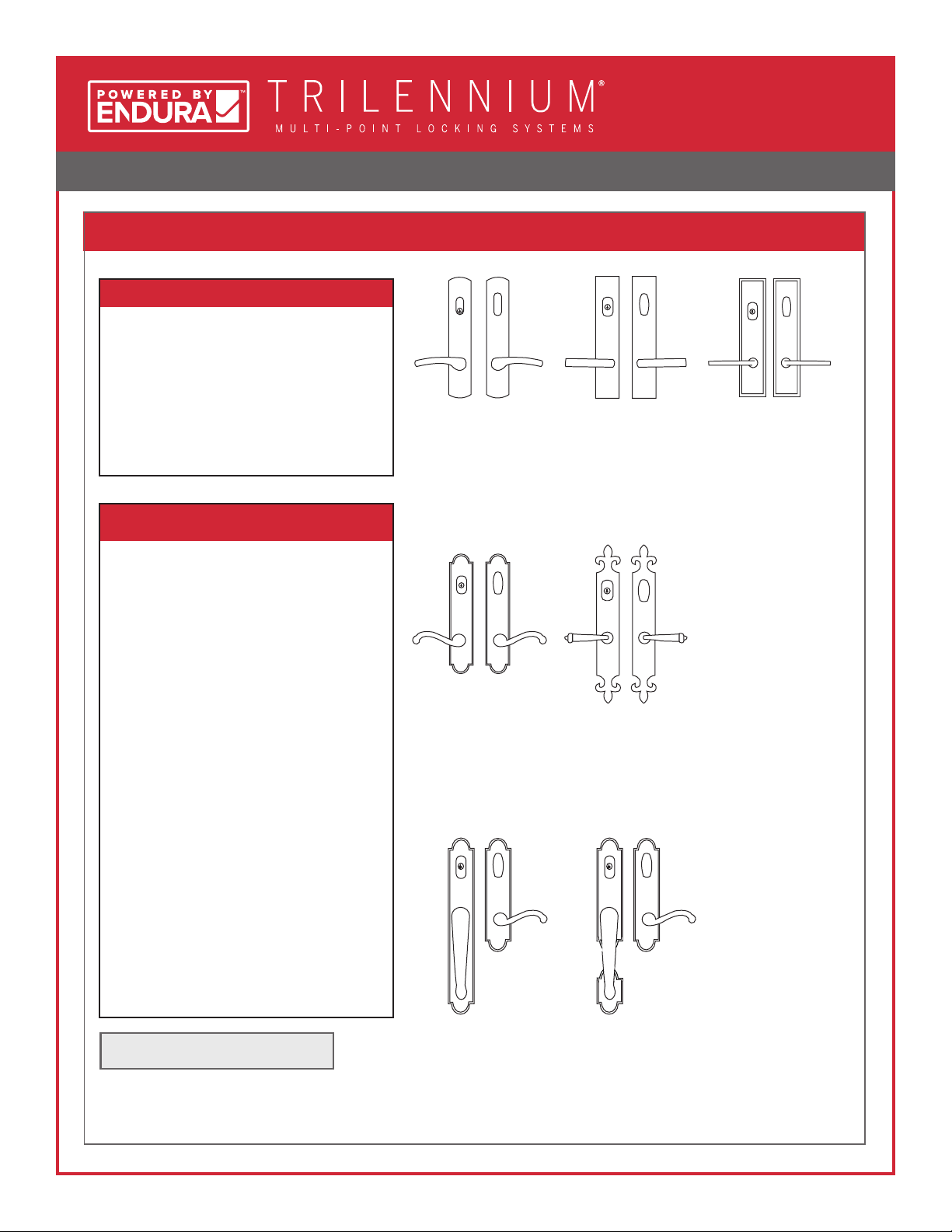
Curved Entry Set Rectangular
Entry Set
Stepped Entry
Set
Arched Entry
Set
Fleur de Lis Entry
Set
Full Length
Entrance Grip
Entry Set
Ø 2-1/8" Crossbore Recommended Sectional
Entrance Grip
Entry Set

HANDLE SET INSTALLATION - ROCKY MOUNTAIN HARDWARE
2 of 12
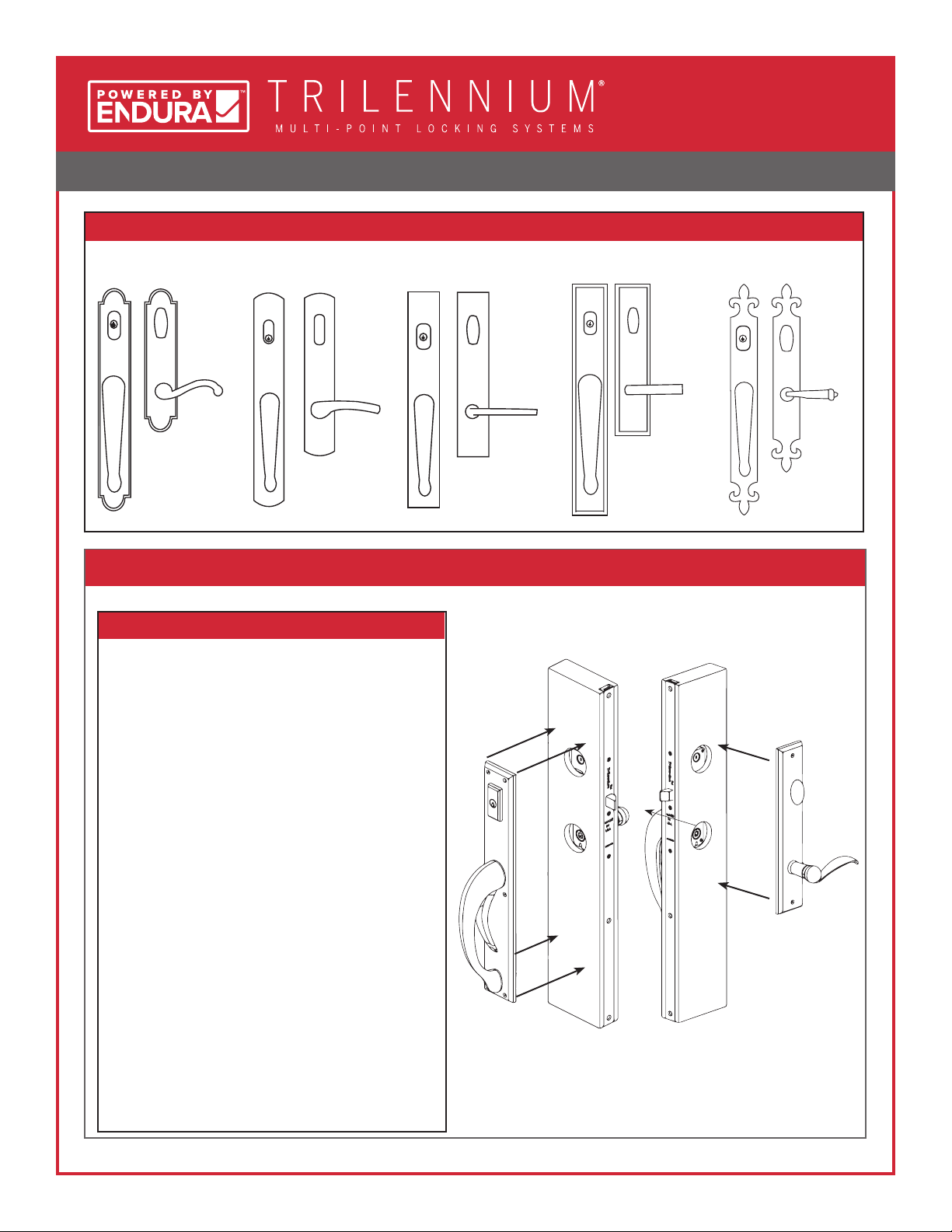
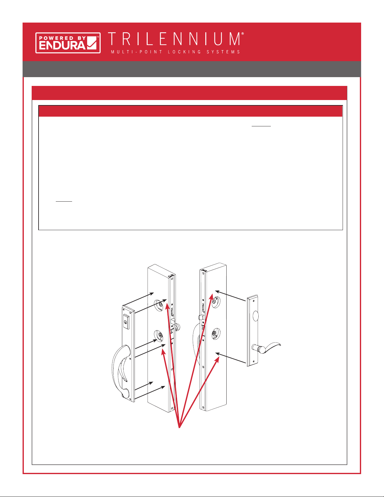
1. DETERMINE WHICH STYLE OF ROCKY MOUNTAIN HARDWARE YOU ARE INSTALLING
TYPE I TYPE II
TYPE III TYPE IV
Arched, Curved,
Rectangular, or
Stepped Lever
Set
Page 3 Page 5
Page 9Page 7
Fleur de Lis
Lever Set
Arched, Curved,
Rectangular,
Stepped, or
Fleur de Lis Full
Length Entrance
Grip
Arched, Curved,
Rectangular,
or Stepped
Sectional
Entrance Grip
Ø 2-1/8" Crossbore
Ø 2-1/8" Crossbore
Ø 2-1/8" Crossbore
Ø 2-1/8" Crossbore

HANDLE SET INSTALLATION - ROCKY MOUNTAIN HARDWARE
3 of 12
1. INSTALL ROCKY MOUNTAIN HARDWARE MOUNTING TEMPLATE
CAUTION:
• Align Rocky Mountain Hardware
template pins with the mounting screw
holes in the body of the Trilennium
Multi-Point Lock.
• Once the Rocky Mountain Hardware
Template is in place, use a 1/4" bit to
drill holes for mounting the hardware.
A. Position mounting template to the door.
• When installing the Arched, Curved,
Rectangular, or Stepped Escutcheon, use
the two holes on the center line of the
template.
Template Pins
Mounting
Screw
Holes
Use these holes
when installing
Arched, Curved,
Rectangular,
and Stepped
Entry Sets.
• Recommended: Drill approximately
halfway through the door on one side.
Remove template and repeat from other
side.
TYPE I
Arched, Curved, Rectangular, or Stepped Lever Set
HANDLE SET INSTALLATION - ROCKY MOUNTAIN HARDWARE
4 of 12
2. ENTRY SET PRE-INSTALLATION SET UP
3. LEVER SET INSTALLATION
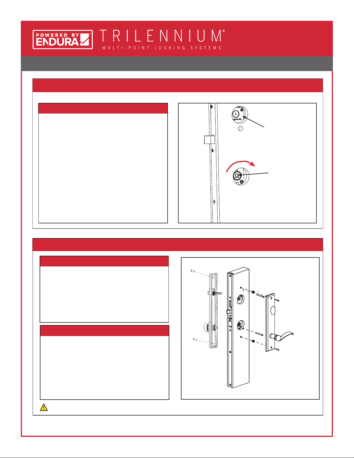
A. Check hardware in door for alignment.
• Door panel should be open. If not, rotate interior
lever actuator hub with at head screwdriver,
turning away from the edge of the door panel.
• Ensure deadbolt slot is in vertical position.
• Ensure latches are in latched position. The
latches should be so they can be easily pushed
in by hand.
• If the latches cannot be depressed, unlock the
door by rotating the deadbolt drive slot using the
cylinder tailpiece, turning away from door edge.
• The cylinder tailpiece projects through the
deadbolt hub slot and is close to ush with the
surface of the door panel (trim as necessary)
• The lever spindle mates to the lever hub of
Trilennium Multi-Point Lock.
• The escutcheon is parallel to panel edge.
• The cylinder tailpiece mates with the thumb turn
slot.
• The spindle mates to the lever hub.
Secure plates by inserting and hand tightening the
(2) #8 mounting screws.
• 2" long for 1- 3/4" doors.
• 2-1/2" long for 2-1/4" doors.
Vertical Deadbolt Slot
Turn to open
A. Install exterior escutcheon rst, then hold in place.
Ensure that:
Ensure that:
B. Install the interior escutcheon.
Check handle’s function (See Page 11) before you fully tighten the handle set to the door.
Interior View

HANDLE SET INSTALLATION - ROCKY MOUNTAIN HARDWARE
5 of 12
1. INSTALL ROCKY MOUNTAIN HARDWARE MOUNTING TEMPLATE
CAUTION:
• Align Rocky Mountain Hardware
Template’s pins with the mounting
screw holes in the body of the
Trilennium Multi-Point Lock.
• Once the Rocky Mountain Hardware
Template is in place, use a 1/4" bit to
drill holes for the mounting hardware.
A. Position mounting template to the door. Template Pins
Mounting
Screw Holes
Use when
installing Fleur de
Lis Entry Set
Lever Set
Mounting
Template
• Recommended: Drill approximately
halfway through the door. Remove
template and repeat from other side.
• When Installing the Fleur de Lis Entry set
use the four holes along the edges.
TYPE II
Fleur de Lis Lever Set
Installed
Template
HANDLE SET INSTALLATION - ROCKY MOUNTAIN HARDWARE
6 of 12
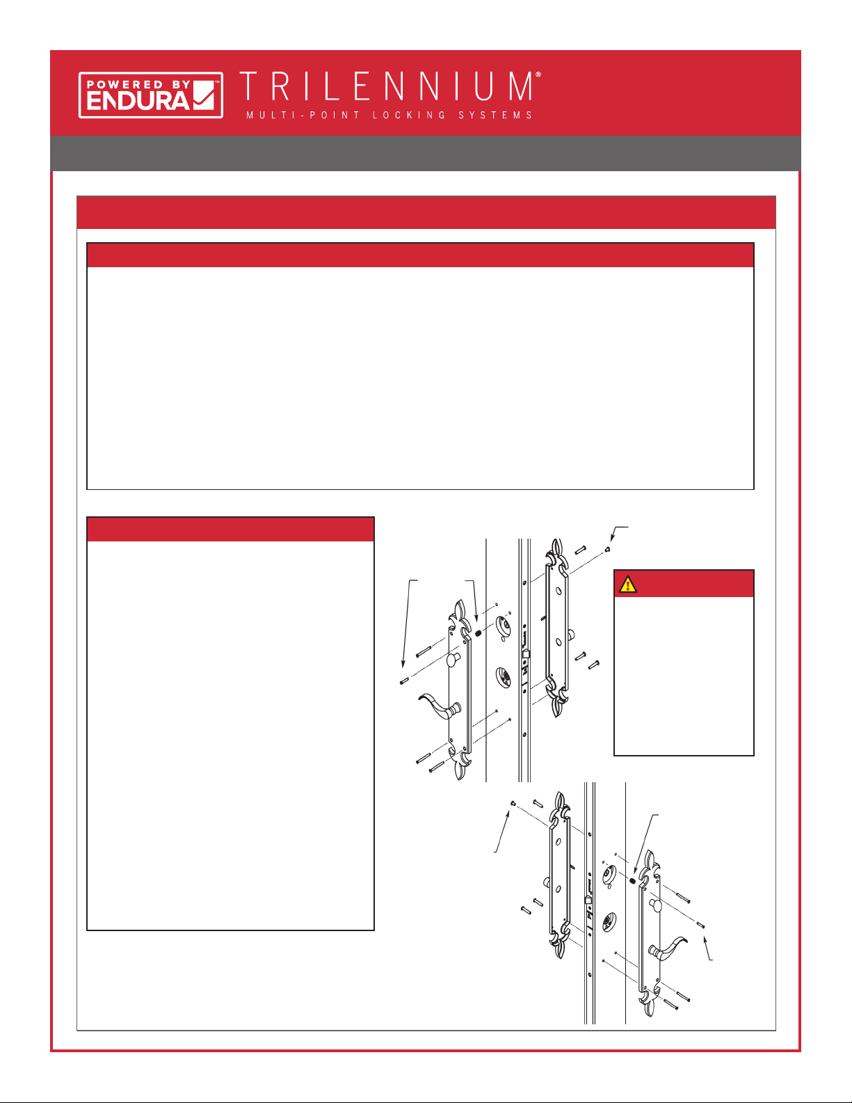
2. FLEUR DE LIS HANDLE SETS INSTALLATION
Right Hand Application See Note
See Note
Left Hand Application
Note: Short
binder post is
pressed into
the exterior
escutcheon.
Note: 8-32
Threaded insert
is installed into
a 1⁄4" Dia. hole
in the door stile
The short
OHMS
screws
into the
threaded
insert.
NOTE:
The top mounting screw,
closest to the edge of
the door cannot be
through-bolted using
the 1-1/4" long binder
post and machine
screw. It interferes with
the operation of the
Trilennium Multi-Point
Lock.
• Install an 8-32 Threaded Insert into the top hole closest to the edge on the interior face of the door.
• Install the short (3/4") Binder Post into the exterior escutcheon’s top hole closest to the edge of the door.
• Insert 1-1/4" Binder Posts into the exterior escutcheon in the remaining 3 holes.
• Guide Cylinder Tailpiece and Lever Spindle on the exterior escutcheon into the respective hubs in the Trilennium
Multi-Point Lock.
Ensure that:
• The cylinder tailpiece projects through the deadbolt hub slot and is close to ush to the door surface (trim as
necessary).
• The lever spindle mates to the lever hub of the Trilennium Multi-Point Lock.
• The escutcheon is parallel to the panel edge.
Ensure that:
• The cylinder tailpiece mates with the
Thumbturn slot.
• The lever spindle mates to the lever hub
of the Trilennium Multi-Point Lock.
• Insert the short (7/8") Oval Head Machine
Screw into top mounting screw hole closest
to the edge of the door and into the Threaded
Insert and loosely tighten. DO NOT FULLY
TIGHTEN.
• Insert the longer Oval Head Machine Screws
into the other 3 mounting holes and loosely
tighten. DO NOT FULLY TIGHTEN.
• Check the handle set’s function (see page 10)
before you fully tighten the handle set to the
door.
• Once you’ve checked the function, re-check
that the escutcheons are parallel to the panel
edge and hand tighten snug. DO NOT OVER-
TIGHTEN.
Additional Parts Included:
(1) 8-32 Threaded insert
(1) 7/8" 8-32 Mounting Screw
(1) 3/4" Binder Post
A. Install the exterior escutcheon rst, then hold in place.
B. Install the interior escutcheon and hold in place.

HANDLE SET INSTALLATION - ROCKY MOUNTAIN HARDWARE
7 of 12
1. INSTALL ROCKY MOUNTAIN HARDWARE MOUNTING TEMPLATE
• Recommended: Drill approximately
halfway through the door. Remove
template and repeat from other side.
• When Installing the Sectional Entry Grip
set use the two holes on the centerline of
the template.
CAUTION:
• Align Rocky Mountain Hardware
Template’s pins with the mounting
screw holes in the body of the
Trilennium Multi-Point Lock.
• Once the Rocky Mountain Hardware
Template is in place, use a 1/4" drill
bit to drill holes for the mounting
hardware.
Position mounting template to the door. Template Pins
Mounting
Screw
Holes
Use when
installing
Sectional
Entry Grip Set
Lever Set
Mounting
Template
TYPE III
Arched, Curved, Rectangular, or Stepped Sectional Entrance Grip
Installed
Template
HANDLE SET INSTALLATION - ROCKY MOUNTAIN HARDWARE
8 of 12
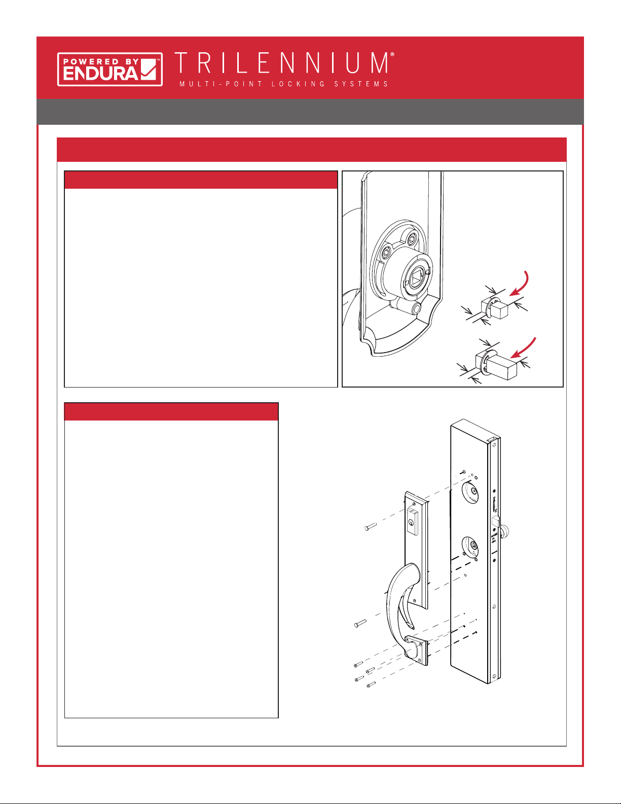
2. ENTRANCE GRIP HANDLES INSTALLATION
Exterior Application
• Insert 1-1/4" Binder Posts into the main exterior escutcheon's
2 holes.
• Install the short end of the square drive spindle into the
exterior grip assembly, as shown on the right.
• Guide Cylinder Tailpiece and Lever Spindle on the exterior
escutcheon into the respective hubs in the Trilennium Multi-
Point Lock.
Ensure that:
• The cylinder tailpiece projects through the deadbolt hub
slot and is approximately ush to the door surface (trim as
necessary).
• The drive spindle mates to the lever hub of the Trilennium
Multi-Point Lock.
• The escutcheon is parallel to the panel edge.
Ensure that:
• The cylinder tailpiece mates with the thumb-
turn slot.
• The lever spindle mates to the lever hub of the
Trilennium Multi-Point Lock.
• Insert the Oval Head Machine Screws into the
2 mounting holes and loosely tighten. DO NOT
FULLY TIGHTEN.
• Check the handle set's function (see page 10)
before you fully tighten the handle set to the
door.
• Once you have checked the function, re-check
that the escutcheons are parallel to the panel
edge and hand tighten snug. DO NOT OVER-
TIGHTEN
• Using a Vix bit, drill pilot holes for the 4 screws
holding the small plate at the bottom of the
exterior grip.
• Install the 4 short Oval Head Wood Screws
directly into the door.
A. Install exterior escutcheon rst, then hold in place.
B. Install the interior escutcheon and hold in place.
1- 3/4" Panel
Application
5/8"
7/8"
2-1/4" Panel
Application
1/4"
1/4"
HANDLE SET INSTALLATION - ROCKY MOUNTAIN HARDWARE
9 of 12
TYPE IV
Arched, Curved, Rectangular, Stepped, or Fleur de Lis Full Length Entrance Grip
1. DETERMINE THE MOUNTING HOLE LOCATIONS
A. Position exterior escutcheon on the door.
• Locate the Exterior Grip Assembly on the door
with the cylinder tailpiece and square drive
spindle installed. Hold against the surface of the
door
• Check to be sure the cylinder tailpiece is
horizontal (the assembly is very heavy and
has a tendency to sag, causing the tailpiece
to point upwards)
• Using a Vix bit or small bit, drill pilot holes in the
center of the top (4) mounting screw locations.
Remove the Exterior Grip Assembly.
• Locate the (2) mounting locations that will have
threaded inserts. These are the top and center
location, CLOSEST to the edge of the door. Using
a 1/4" bit, drill these holes 3/8" to 1/2" deep and
install the threaded inserts ush to the face of
the door.
• Locate the (2) mounting locations that will be
through-bolted. These are the top and center
location, FURTHEST from the edge of the door.
Using a 1/4" bit, drill these (2) holes through the
door.
HANDLE SET INSTALLATION - ROCKY MOUNTAIN HARDWARE
10 of 12
2. FULL LENGTH ENTRANCE GRIP HANDLE INSTALLATION
• Install the Exterior Grip Assembly on the door using the (4) locations from Step 1. DO NOT install the bottom (2) wood
screws yet.
• Check that the Exterior Grip Assembly is parallel to the edge of the door.
• Hand tighten the mounting screws and check the function.
• Locate the Interior Lever Assembly with the cylinder tailpiece engaged in the thumbturn and the square spindle in the
lever. Hold against the surface of the door.
• Using a Vix bit or small bit, drill pilot holes in the center of the mounting screw locations. There are (4) screws for the
Fleur de Lis and (2) for all other styles.Remove the Interior Lever Assembly.
• Using a 1/4" bit, drill these holes 3/8" to 1/2" deep and install the threaded inserts ush to the face of the door.
• Install the Interior Lever Assembly on the door. Hand tighten the mounting screws and check the function.
• Before tightening the mounting screws further, engage the deadbolt and use the interior panic release several times.
• This will allow the handle set to nd it's "sweet spot" and function smoothly. Once you are happy with the function,
recheck the escutcheon plates are parallel to the edge of the door, hand tighten the screws and add the (2) wood
screws to the bottom of the Exterior Grip Assembly.
A. Install exterior escutcheon rst, then hold in place.
Exterior Application Interior Application
Note: 8-32 Threaded insert is
installed into a 1⁄4" Dia. hole in
the door stile (4 places).
Note: You can use the
Rocky Mountain Hardware
Template for the INTERIOR
ONLY as it is done for Type I.
(See Step #1, Page 3)

HANDLE SET INSTALLATION - ROCKY MOUNTAIN HARDWARE
11 of 12
4. CHECK OPERATION OF ENTRY SET
A. Verify lock and handle operation with the door open.
• Rotate thumbturn 90°. Latch bolts should extend to deadbolted position. Rotate 90° the other direction. The
latch bolts should retract to original position.
• Rotate thumbturn 90° again. Latch bolts should extend to deadbolted position.
• Press on the end of each latch bolt individually to ensure they do not collapse. If they do, the door is not fully
deadbolted. Check the fabrication to see where the interference is.
• Operate exterior grip trigger. The latch bolts should remain in deadbolted position.
• Operate interior lever downward. The latch bolts should fully retract.
• Operate exterior grip lever. The latch bolts should fully retract.
HANDLE SET INSTALLATION - ROCKY MOUNTAIN HARDWARE
12 of 12
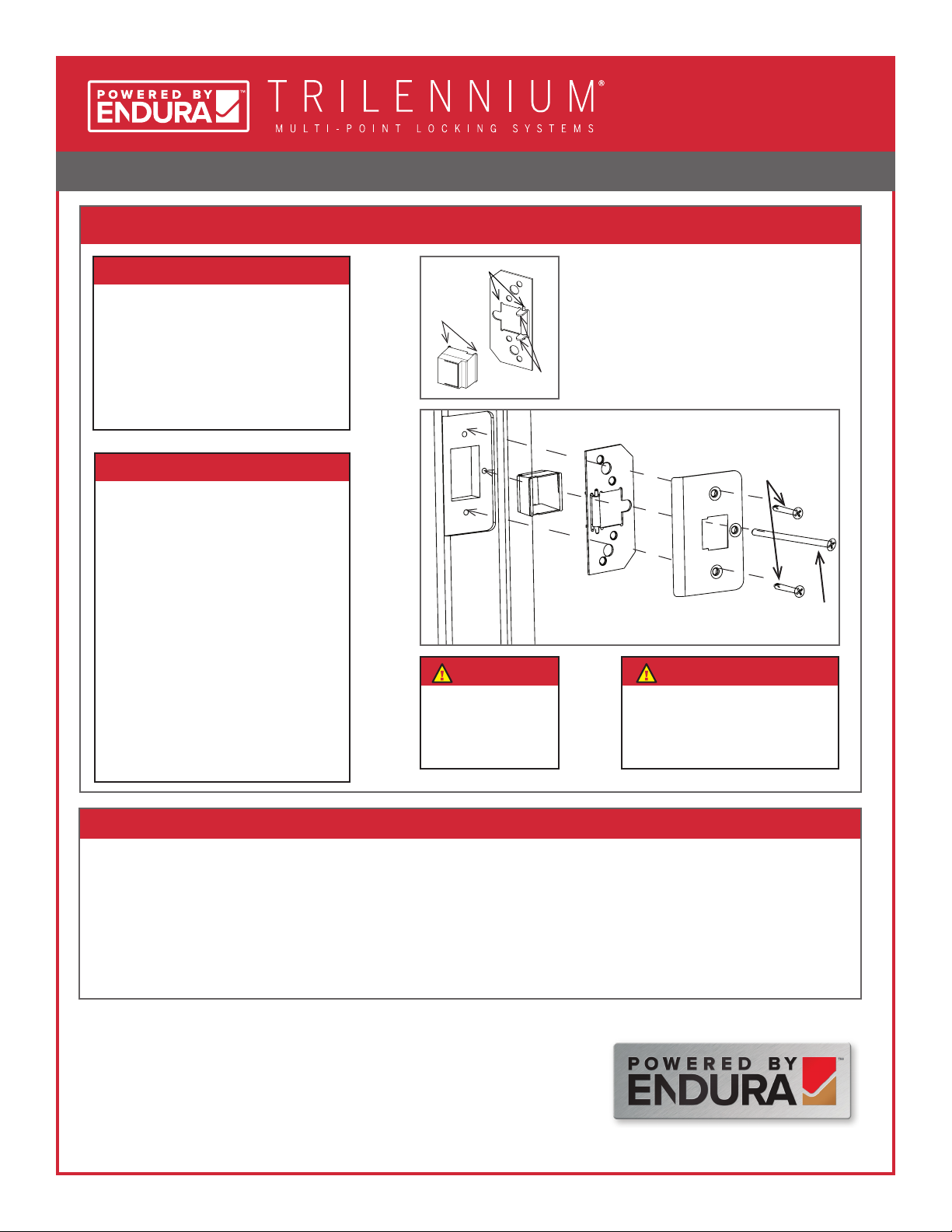
5. Strike Plate Assembly
• Attach the Dust Box to the
Reinforcing Plate.
• Align the 3 holes on the Strike Plate
with the Reinforcing Plate.
• Orient as shown.
• Use 3/4" screws in top and bottom
holes of each strike.
• Use long #10 x 2-1/2" Screw in
center hole. (The purpose is to
anchor each Strike Plate to the
structural framing for added
security.)
• Repeat for remaining strike
locations.
• Close the door.
• All three bolts should engage strikes as door is closed.
• Turn thumbturn 90° to extend bolts (all three) an additional 1/2" to deadbolted position.
• From interior, rotate lever downward to totally disengage bolts and open door. Bolts can also be disengaged (to latched
position) by turning thumbturn.
• Engage deadbolt again. From the exterior, operate the lever and ensure it does not move. Ensure latches only move when
the door is unlocked with a key.
Attach strike plates to jamb
6. Final Operation Check
A 1/8" Ø pilot hole
should be drilled into
the rough framing
for the long screw.
Note:
Solid shimming should be
placed behind the jamb at each
strike location to allow for rm
anchoring to structure.
Note:
8817 W. Market St., Colfax, NC 27235
1.800.334.2006 www.enduraproducts.com
The information contained in this document is the condential and proprietary information and trade secrets of Endura Products, Inc. Any disclosure,
use or dissemination of such information without the express written permission of Endura Products, Inc. is strictly prohibited. Endura Products, Inc.
also owns any and all intellectual property rights embodied in such information, including patent rights, copyrights, and trademark rights, and no
license of any intellectual property right is intended, nor should any license be implied, as a result of the receipt of this document.
Rev. 01.16.2018
Parts Required
• (3) Dust Boxes
• (3) Reinforcing Plates
• (3) Strike Plates
• (6) 3/4" screws
• (3) #10 x 2-1/2" screws
• The Dust Box Feet should align with the
slots in the reinforcing plate.
• The reinforcing plate arms should sit inside
the dust box.
Dust Box
Reinforcing Plate
Strike Plate
3/4" Screws
#10 x 2-1/2"
Screw
Dust Box
Feet
Reinforcing
Plate Arms
Slots for Dust Box Feet
Other manuals for TRILENNIUM Series
2
Other Endura Power Tools Accessories manuals


