ENEKA Greasly-A User manual


2
Free-standing Grease Separator
For room installation
Main parameters
Type :
Serial number :
Flow rate :
Client :
Installation place :

3
Table of Contents
1. GENERAL INFORMATION.....................................................................................5
1.1. Introduction.........................................................................................................5
1.2. Product description.............................................................................................5
1.3. Operation principle..............................................................................................5
1.4. Technical data ....................................................................................................6
2. MODELS ..............................................................................................................7
2.1. Model Base.........................................................................................................7
2.2. Model PRIMA......................................................................................................7
2.3. Model MIX...........................................................................................................8
2.4. Model PUMP.......................................................................................................8
2.5.
Component assemblies
........................................................................................9
2.6. Nameplate ........................................................................................................10
3. SAFETY..............................................................................................................10
3.1. Correct intended use.........................................................................................10
3.2. Staff ..................................................................................................................10
3.3. Electrical safety.................................................................................................10
3.4. Other safety precautions...................................................................................11
4. TRANSPORTATION...........................................................................................11
5. INSTALLATION..................................................................................................12
5.1. Selection of location..........................................................................................12
5.2. Assembly of components..................................................................................13
5.2.1. Inspection window........................................................................................13
5.2.2. Extraction pipe .............................................................................................13
5.2.3. Refilling unit..................................................................................................14
5.2.5. Grease alarm...................................................................................................15
5.2.6. Disposal Pump................................................................................................16
5.2.7. Control Panel for automatic operation (model Pump)......................................17
5.3. CONNECTIONS/SUPPLIES.............................................................................21
5.3.1. Inlet and outlet connections..........................................................................21
5.3.2. Pipeline insulation/heating ...........................................................................21
5.3.3. Sampling chamber.......................................................................................21
5.3.4. Ventilation ....................................................................................................22
5.3.5. Disposal line.................................................................................................22
5.3.6. Freshwater connection.................................................................................23
6. COMMISSIONING..............................................................................................23
6.1. Procedures .......................................................................................................23

4
6.2. Acceptance Report ...............................................................23
7. OPERATION.......................................................................................................23
7.1. Check................................................................................................................24
7.2. Disposal............................................................................................................24
7.3. Yearly maintenance..........................................................................................25
7.4. General inspection............................................................................................25
7.5. Service log........................................................................................................25
8. WARRANTY.......................................................................................................25
9. DECLARATION..................................................................................................26
5
1. GENERAL INFORMATION
1.1. Introduction
Dear customer,
We are pleased that you decided to purchase one of our products which will certainly
completely match your requirements. We wish you a smooth and successful installation and
operation. We try to keep our quality standards as high as possible therefore we are open for
your feedback on any possible improvements.
1.2. Product description
Grease separators described in this installation, operation and maintenance manual meet the
latest European regulations. GREASLY-A was designed according to EN 1825 and DIN 4040
standards. After treatment, the grease concentration shall not exceed 25 mg/l.
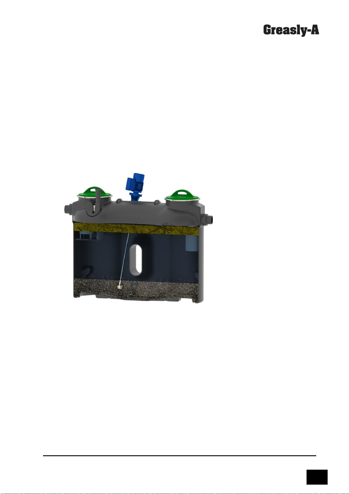
1.3. Operation principle
Figure 1. Operation of the Grease separator
Incoming greasy wastewater enters the grease separator through a unique inlet module which
creates the circular flow path. As water passes through the separator, grease particles, lighter
than water, are driven upwards by gravity and accumulated in the grease collection area on
the water surface. At the same time, solids and other impurities heavier than water settle to
sludge trap at the bottom of the tank. Treated water is discharged through the outlet pipe.

6
1.4. Technical data
Table 1. Technical data
Model
Flow
rate
l/s
Sludge
trap
volume,
litres
Grease
separation
volume,
litres
Grease
collection
volume,
litres
Total
volume,
litres
Dimensions mm
Weight kg, model
L
B
H
Base
Prima
Mix
Pump
Greasly-
2A
2
200
450
80
650
1940
700
1190
68
78
119
144
Greasly-
4A
4
400
450
160
850
1940
700
1430
81
91
132
157

7
2. MODELS
2.1. Model Base
Figure 2. Greasly-4A-BASE
Model BASE can be applied in areas where bad odour during maintenance is not causing any
inconvenience. Access cover shall be opened for disposal of accumulated grease and solids
by a vacuum truck.
2.2. Model PRIMA
Figure 3. Greasly-2A-PRIMA
Model PRIMA provides odour-free operation without the need for opening of the cover. The
separator is equipped with manual disposal system. Accumulated grease and sludge are
disposed throughthe Extraction pipe by a vacuumtruck. After complete disposal,the separator
is filled-up with fresh water through the Refilling unit.
8
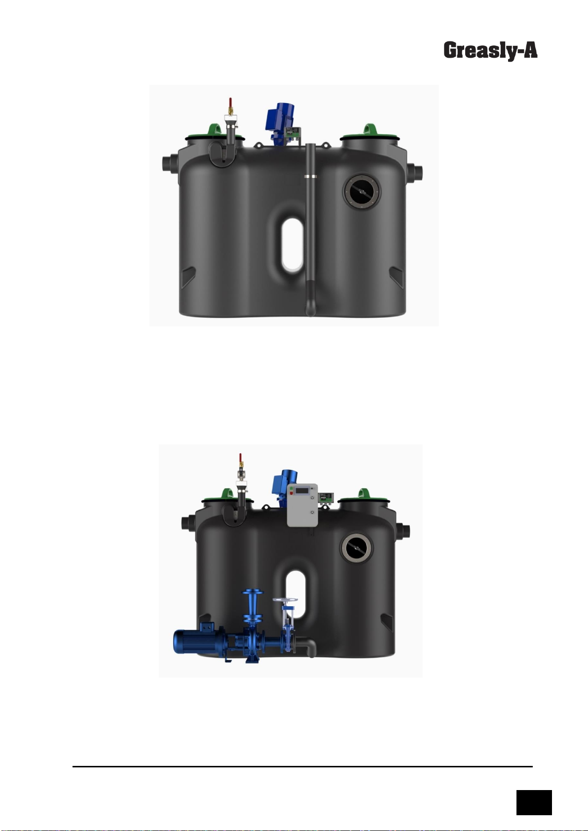
2.3. Model MIX
Figure 4. Greasly-4A-MIX
Model MIX is equipped with Grease alarm is indicating when the maximum level of
accumulated grease is reached. Before emptying, Mixer actuated for blending grease, water
and solid layersthus facilitatingemptying of the separator. Aspecial Extraction pipe is provided
for the emptying of grease separator by the vacuum truck. After complete disposal, the
separator is filled-up with freshwater.
2.4. Model PUMP
Figure 5. Greasly-4A-PUMP
Model PUMP is equipped with an automatic program-controlled emptying system including a
Disposal pump. When the maximum level of accumulated grease is reached, grease sensor
activates the alarm. After connecting the hose to a disposal truck, the operator starts the
disposal procedure by pushing a START button in the control box or remote controller. First of
all, the mixer is turned on for blending grease, water and solid layers. Then the Disposal pump

9
is actuated for emptying of the separator. After complete disposal, the
separator can be rinsed (option) by partial filling the freshwater through the Refilling unit,
mixing and emptying by the Disposal pump. After rinsing, the separator is completely filled-up
with freshwater again.
2.5.
Component assemblies
Model BASE / PIRIMA / MIX:
A - Separator body
B - Lid with locking ring and
gasket
C - Inspection window (Prima,
Mix)
D - Extraction pipe (Prima, Mix)
E - Manual Refi
lling unit (Prima,
Mix)
F - Mixer (model Mix)
G –Grease alarm (option)
Model PUMP:
A - Separator body
B - Lid with locking ring and
gasket
C - Inspection window
F - Mixer
G –Grease alarm
H –Control Panel
Y - Automatic Refi
lling unit
J –Disposal Pump
Figure 6. Components of
Greasly-A

10
2.6. Nameplate
Figure 7. Nameplate
3. SAFETY
3.1. Correct intended use
The Grease separator is intended only for separation of FOG (fats, oils & grease) of
vegetable or animal origin from wastewater. The use of the system for any other purpose
is not regarded as correct and the manufacturer is not liable for any damage resulting from
improper use; the responsibility is born by the owner/operator.
The correct intended use also includes adherence to assembly, commissioning, operating and
servicing conditions set out bythis manual. Forsafetyreasons, conversionworks atthe system
are not permitted.
The correct intended use also includes observing national laws and regulations.
The operatingmanual shall always be available at the location where theseparator is installed.
3.2. Staff
People who operate/or install the separator shall be of more than 18 years of age, shall have
been trained for the respective tasks, and shall follow the local safety regulations. The owner
of the system shall ensure that only qualified staff work on the grease separator.
3.3. Electrical safety
Note: All electrical connections shall be carried out by a qualified contractor.
The electricalinstallation shall comply withthe specifications accordingto European standards
EN1012 and EN60 204.
Before the maintenanceof any electrical component (mixer/disposal pump/Automatic Refilling
unit, Grease alarm) the electrical supply shall be turned off.
In case of smoke or strange sounds appear, immediately switch-off the separator from the
power supply.

11
3.4. Other safety precautions
Never take off the covers while operation.
Do not disassemble or turn off safety components.
Do not leave any hard objects and tools that can block free access to the separator.
During cleaning work, greasy liquid and/or grease can wet the floor. This results in a slipping
hazard. Always eliminate any liquid and/or grease that has leaked immediately, and wear
suitable footwear.
The wastewater contains bacteria. Any parts of the body which come into contact with
wastewater shall be cleaned immediately, change soiled clothing. Wear personal protective
equipment.
Blocked pipelines may cause a pressure rise which may damage the system and harm to
maintenance personnel. While disposal of the system, ensure good ventilation to avoid the
building of vacuum inside of separator which may cause the damage of the separator body.
4. TRANSPORTATION
Following rules shall be kept during transportation:
Normally, the system is supplied completely mounted and fixed on a wooden pallet and
wrapped in a foil.
The capacity of the forklift truck / any other lifting equipment shall exceed the weight of the
separator.
When lifting the separator, the ropes/chains must be attached only to the appropriate lifting
lugs.
If ropes/chains are touching the body of the separator, the extra soft spacers are needed to
keep body undamaged.
While lifting and transporting it is necessary to avoid the active shaking of the separator.
Transportation protections that are mounted on the device can be removed only when the
separator is in its working space.
12
5. INSTALLATION
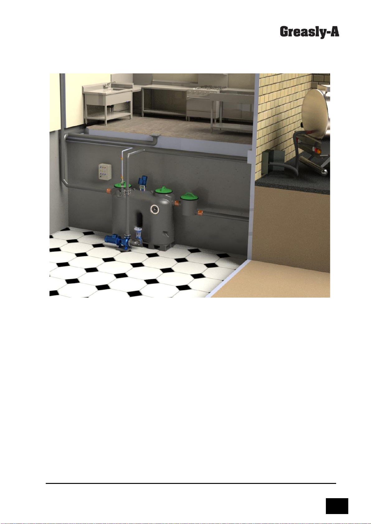
5.1. Selection of location
Figure 8. Example of installation
Grease separators shallbe installed close to the source of wastewater. Do not site the systems
in unventilated rooms, on roads, car parks or in storage areas. The separators shall be easily
accessible to cleaning vehicles.
Before installation of grease separator following conditions shall be checked:
- The room shall be protected from frost (recommended temperature >15 °C).
- The room shall be well vented/ventilated.
- The floor shall be a horizontal, rigid surface capable of bearing an appropriate load.
- The floor shall be equipped with an integrated drain.
- To prevent bad odour, separators shall not be sited close to residential buildings, close
to windows and air intakes.
- The installation location of the separator shall have sufficient light.
- Separator shall be easily accessible to vacuum vehicles.
- Space shall be sufficient for the maintenance. Room height shall be 60 cm higher than
grease separator to enable the opening of the covers during the maintenance. Free space of
1 m in front of separator shall be available.
- Cold and hot water connections available.
- Inlet pipe with stilling section of min. 1 m available.
- The inlet and outlet pipelines shall have a gradient of 2%.
- If the inlet pipe is longer than 10 m it shall be equipped with a separate vent.
13
5.2. Assembly of components
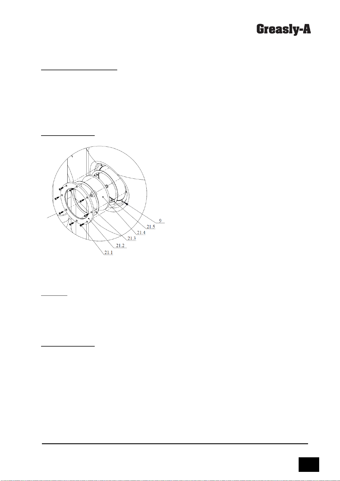
5.2.1. Inspection window
Package (please see fig.9):
- 1 pc Window with wiper no. 21.4
- 1 pc Flange no. 21.2, material stainless steel
- 1 pc Gasket between flange and window no. 21.3 (C4400 material)
- 1 pc Gasket between window and separator body no. 21.5 (rubber material)
- 8 pcs Screws M6 no. 21.1
Special tools required: Ø 177 mm drill crown
Installation process
Figure 9. Installation of inspection window
Select the side for installation of inspection
window depending on the layout of the
system and inlet and outlet pipes in the room.
Cut an opening using a drill crown of Ø177
mm diameter. The inspection window is to be
placed in the following order: 1) rubber
gasket, 2) window with a wiper; 3) C4400
gasket; 4) Flange.Tighten the flange with the
screws.
5.2.2. Extraction pipe
Package:
- 1 pc Extraction pipe DN65, polyethylene
- 1 pc Rubber coupling ø75 mm
- 1 pc Pipe bracket 2½”
Special tools required: Ø 65 mm drill crown
Installation process

14
5.2.3. Refilling unit
Package:
- 1 pc Siphon no. 23.1
- 1 pc Siphon retainer no. 23.2 with screw M6 no. 23.7
- 1 pc Manual ball valve DN20 no. 23.4
- 1 pc Valve holder no. 23.3 with screw M8 no. 23.5 and bracket 23.8
- 1 pc Solenoid valve no. 23.10 (model Pump only)
- 1 pc Gasket DN50/65 NBR no. 23.9
Special tools required: Ø 70 mm drill crown.
Installation process
2 locations for connection of the
Refilling unit are available on both
sides of the separator. Cut the opening
at the market area by a Ø70 mm drill
crown. Insert a rubber gasket into the
opening and attach a siphon. Tighten
the siphon to the separator housing
from by stainless steel retainer plate
and a screw. Do not apply too much
force. Install the valves to their holder.
Attach the metal bracket is attached to
the siphon neck and tighten the valve
holder by the screw.
Figure 11. Fitting of Refilling unit
Figure 10. Extraction pipe and rubber coupling
Drill an opening of Ø65 mm using a
drill crown in thenozzle at the bottom
of the unit. Attach the extraction pipe
by the rubber coupling to the nozzle,
and tighten the metal clamps

15
5.2.4. Mixer
Package:
- 1 pc Mixer with motor
- 4 pcs Screw M12
- 1 pc Gasket
Special tools required: 32 mm drill
Installation process
The mixer shall be installed at the
top of the tank. Drill an opening by
the drill bit of 32 mm diameter, the
center is marked. Place the gasket
between the tank body and the
mixer’s flange. Tighten the flange to
the separator body with 4 bolts. Do
not apply too much force.
Figure 12. Fitting of Mixer
5.2.5. Grease alarm
Package:
- 1 pc grease alarm type GA-1 (panel and sensor)
- 2 pcs bracket for the alarm unit
- 2 pcs screws M6 & 4 pcs screws M4
Installation process
The grease alarm panel is to be fitted to the bracket which is attached to the separator body.
Tighten two metal brackets to the housing by 2 screws M6 provided. Fit the panel to the
brackets by 4 crews M4.
Drill a ø12 mm opening for the sensor cable on the top of the separator body in the area as
indicated in figure 13. Route the cable through the cable duct. Screw the cable duct to the
separator wall. The sensor is to be suspended at the height of 150 mm below the static water
level i.e. the bottom of the outlet nozzle.
Electrical connections of Grease alarm shall be installed according to figure 13.

16
Figure 13. Installation of Grease alarm
5.2.6. Disposal Pump
Package:
1 pc Heavy-duty disposal pump with Vortex impeller, motor 2,2kW 400V 50Hz
1 pc Gate valve DN65
1 pc Suction pipe DN65, PE
1 pc Rubber coupling ø75 mm with 2 clamps
1 pc Double flanged pipe DN65, cast iron
1 pc Pipe adapter DN50/65
Installation process
•The disposal pump unit (pump with motor, double flanged pipe, adapter) is supplied
completely assembled.
•Drill an opening of Ø65 mm using a drill crown in the nozzle at the bottom of the tank.
•Place the disposal pump on a rubber anti-vibration matt.
•Attach the suction pipe by the rubbercoupling tothe tank, and tightenthe metalclamps.
•Connect the suction pipe and gate valve to the double flanged pipe.

17
•Bolt the pump to the floor.
Figure 14. Fitting of Disposal Pump
5.2.7. Control Panel for automatic operation (model Pump)
Package:
- 1 pc Control Panel
- 1 pc Remote controller (option)
Installation process
•Attach the control panel to the wall in an easily accessible area.
•Connect the power supply, cables to a mixer, disposal pump, solenoid valve and
remote controller to the marked terminals and according to the wiring diagram (fig.
15).

18
Figure 15. Wiring diagram

19
Operation
After connecting the hose to a disposal
truck, the operator starts the disposal
procedure by pushing a START button in
the control box or remote controller.
Disposal steps:
- Mixing for a preset time.
- Emptying by the disposal pump.
- Rinsing (optional), i.e. partial filling
with freshwater and emptying.
- Complete filling with freshwater.
During operation, the control panel
monitors the current used by the mixer
and pump motors and compares it with a
preset rated current. If the current is too
low, the "dry run" is recorded, if it is too
high, the overload is recorded. In both
cases, the motor will be switched off.
In case of an emergency, the process can
be stopped by pressing the Red / STOP
button.
Fig. 16. Control panel and remote controller
Standby mode
0
1
2
3
4
5
6
7
8
9
0
1
2
3
4
5
6
7
8
9
0
1
S
Y
S
T
E
M
R
E
A
D
Y
2
M
I
X
E
R
O
F
F
I
:
1
,
5
A
3
P
U
M
P
O
F
F
I
:
7
,
5
A
4
W
A
T
E
R
O
F
F
2nd row: indication of the preset current of a mixer motor.
3rd row: indication of the preset current of a pump motor.
Indication after START
a) Mixing cycle
0
1
2
3
4
5
6
7
8
9
0
1
2
3
4
5
6
7
8
9
0
1
S
T
A
R
T
T
I
M
E
0
:
2
0
T
M
3
0
2
M
I
X
E
R
O
N
T
0
:
1
5
T
M
2
0
3
P
U
M
P
O
F
F
4
W
A
T
E
R
O
F
F
1st row: Disposal period after the start. TM –preset time of all disposal steps.
2nd row: Time in reverse mode from the beginning of the mixing cycle until the preset time
TM.

20
b) Emptying cycle
The disposal pump is running. At the end of the emptying cycle, the solenoid valve is opened
to supply the freshwater and to facilitate the complete emptying. The pump is switched off
when the consumption of electrical current is decreasing after complete emptying of the
separator contents.
3rd row:
Time in
reverse mode from the beginning of the Emptying cycle until the preset time TM.
4th row: Time in reverse mode from the opening of the solenoid valve until the preset time TM.
c) Rinsing cycle (option)
The separator is filled up to half of its volume with freshwater by opening the solenoid valve of
the refilling unit. Then the water is emptied.
Partial filling
4th row: Time in reverse mode from the opening of the solenoid valve until the preset time TM.
Emptying
3rd row:
Time in
reverse mode from the beginning of the Emptying cycle until the preset time TM.
e) Filling cycle
0
1
2
3
4
5
6
7
8
9
0
1
2
3
4
5
6
7
8
9
0
1
S
T
A
R
T
T
I
M
E
0
:
2
5
T
M
3
0
2
M
I
X
E
R
O
F
F
T
M
2
0
3
P
U
M
P
O
F
F
T
M
1
0
4
W
A
T
E
R
O
N
T
0
:
1
2
T
M
1
5
Settings
The grease separator is supplied with the factory settings. If necessary, the setting can be
modified with the rotary knob SET. The SET knob has two control functions. The seting is
selected by pressing the knob. The value of the parameter is reduced by turning the knob
counterclockwise and increased by turning it clockwise.
1 - Start
By pressing the rotary knob, the disposal cycle is started (the same as after pressing the start
button).
2 –Manual
In the manual mode, each device can be turned on and off.
0
1
2
3
4
5
6
7
8
9
0
1
2
3
4
5
6
7
8
9
0
1
S
T
A
R
T
T
I
M
E
0
:
2
5
T
M
3
0
2
M
I
X
E
R
O
F
F
T
M
2
0
3
P
U
M
P
O
N
T
0
:
1
5
T
M
1
0
4
W
A
T
E
R
O
N
T
0
:
5
T
M
8
0
1
2
3
4
5
6
7
8
9
0
1
2
3
4
5
6
7
8
9
0
1
S
T
A
R
T
T
I
M
E
0
:
2
5
T
M
3
0
2
M
I
X
E
R
O
F
F
T
M
2
0
3
P
U
M
P
O
F
F
T
M
1
0
4
W
A
T
E
R
O
N
T
0
:
1
2
T
M
8
0
1
2
3
4
5
6
7
8
9
0
1
2
3
4
5
6
7
8
9
0
1
S
T
A
R
T
T
I
M
E
0
:
2
5
T
M
3
0
2
M
I
X
E
R
O
F
F
T
M
2
0
3
P
U
M
P
O
N
T
0
:
1
5
T
M
1
0
4
W
A
T
E
R
O
N
T
0
:
5
T
M
8
This manual suits for next models
7
Table of contents
Popular Water Filtration System manuals by other brands


Nimbus Water Systems
Nimbus Water Systems Cascade NS-14 Owner's manual and installation guide

EFI
EFI DPF12015R Instruction bulletin

Celestron
Celestron ECLIPSMART 94248 manual

Oase
Oase BioSmart 5000 operating instructions

Zenith
Zenith Filter Tap Installation and operating instructions

Goldine Controls
Goldine Controls Pro Logic PL-P-4 installation manual

Aquasana
Aquasana Claryum 2-Stage owner's manual

Esta
Esta VACUMAT 1000 operating instructions

Lucent Technologies
Lucent Technologies AnyMedia PFU500 manual

Culligan
Culligan AQUA-CLEER BXL Series Installation and operating instructions

urmet domus
urmet domus Agora 1372 Installation sheet

Gow-Mac
Gow-Mac 75-850-BV operating manual