Gow-Mac 75-850-BV User manual

Operating Manual
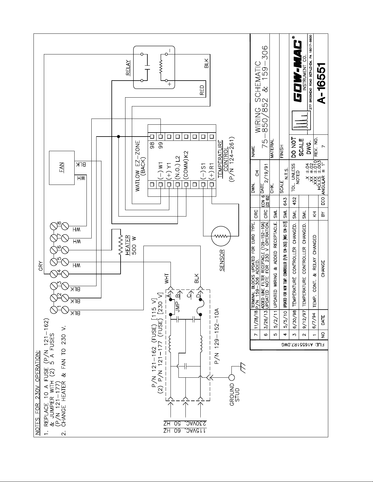
Model 75-850-BV & 75-852-BV
Hydrogen Separator
with Manual Bypass Valve
Model 75-850-BV: 120 V, 50/60 Hz
Model 75-852-BV: 230 V, 50/60 Hz
September 2020
Rev. 7
READ INSTRUCTIONS
BEFORE OPERATING
277 Brodhead Road, Bethlehem, PA 18017-8600 U.S.A. Tel: (610) 954-9000

GOW-MAC Instrument Co.
2

Model 75-850-BV / 75-852-BV H2Separator w/ Manual Bypass Valve
09/20 Rev. 7
3
GOW-MAC Model 75-850-BV or 75-852-BV
Hydrogen Separator
1. Connections
1. ConnectAIRCYLINDERtothebackoftheHydrogenSeparatoratAIRtting.
2. Using the ROTAMETER located on the front panel of the Separator, set the AIR
FLOW to the optimum setting according to the chromatogram located at the back of
thismanual.Theowofaircanrangebetween100-300ml/min.
3. Using the 1/16" VCR tubing that is supplied, connect the Separator to the Series 590
DIDGCasfollows:
THE INLET/OUTLET FITTINGS ARE VCR TYPE AND
WASHERS MUST BE USED. CHECK THE CARRIER FLOW
RATE TO BE SURE THAT NOTHING HAS CHANGED.
a.Connectoneendofthesuppliedtubingto"FROMINST"ttinglocatedonthe
side of the Model 75-850-BV or 75-852-BV and the other end of the tubing to "TO
SEP"ttinglocatedontherearoftheGC.
b.Connectoneendofanotherpieceofthesuppliedtubingto"TOINST"tting
located on the side of the Model 75-850-BV or 75-852-BV and the other end of
thetubingto"FROMSEP"ttinglocatedontherearoftheGC.
c. Turn BYPASS VALVE to SERIES/RUN position.

GOW-MAC Instrument Co.
4
Separator/Series 590 GC Connections
FlowDiagram
2. Settings
1. At this point, turn the H2Separator ON and set the operating temperature according
to the optimum temperature setting on the chromatogram located at the back of this
manual.Theoperatingrangeforthetemperatureisbetween85°-450°C.
a.PresseitherUP-arroworDOWN-arrowkeyuntilthedesiredtemperatureis
displayed. Refer to the chromatogram located in the back of this manual for
correcttemperature.Afewsecondsafterthetemperatureisset,thecontrollerwill
start to adjust the temperature automatically.
b. Once the temperature is reached, the H2separator is ready for use. Inject H2
samplesjustliketheywereanynormalGCinjection,followingtheinstruments’
normal operating procedures.
c.Ifthehydrogenstartstopreventtheanalysisfrombeingperformed,lowertheair
owtoseeifthequalityoftheanalysisimproves.Ifitdoesnot,tryvaryingthe
temperature,inapproximately50°Cincrements,higherorloweruntilthereisa
reduction in the hydrogen breaking though. If the removal of the hydrogen is still
insucientenoughtoallowforaqualitativeandquantitativeanalysis,recondition
the Separator as directed in instructions found later in this manual entitled,
" Hydrogen Breakthrough."
AIR IN
AIR FLOWMETER
WITH VA LV E
FROM
INST.
VENT
HEATED BOX
H2 SEP.
TO
INST.
5
6
4
3
1
2

Model 75-850-BV / 75-852-BV H2Separator w/ Manual Bypass Valve
09/20 Rev. 7
5
3. Controls
A.PowerSwitch/CircuitBreaker:TurnsACpowerON/OFF.
B. Temperature Controller:
WATLOW
EZ-ZONE®
EZ
°F
°C
%
1
2
3
4
5
...
...
.
.
Z
O
N
E
C. BypassValve:AllowstheusertoconnecttheSeparatortotheSeries590DIDGC
or bypass the Separator.
4. Responding to a Displayed Message/Error Code
Anactivemessagewillcausethedisplaytotogglebetweenthenormalsettingsandthe
active message in the upper display and [Attn]inthelowerdisplay.
Yourresponsewilldependonthemessageandthecontrollersettings.Some
messages,suchasRampingandTuning,indicatethataprocessisunderway.Ifthe
messagewasgeneratedbyalatchedalarmorlimitcondition,themessagecanbe
clearedwhentheconditionnolongerexists.Ifanalarmhassilencingenabled,itcan
be silenced.
Upper Display: In the Home
page, displays the process
value,otherwise displaysthe
value of the parameter in the
lowerdisplay.
Lower Display: Indicates
thesetpointoroutputpower
value during operation, or
the parameter whose value
appears in the upper display.
EZ Key: Enables simple, one-
touchoperationofuserdened,
repetitive activities. This key
can be programmed to do
various tasks, such as locking
the keyboard, restoring user
settings, etc.
ZONE: Indicates the controller
zone (1-9).
Advance Key: Advances
through parameter prompts.
Up and Down Keys: In the Home
page, adjusts the set point in the
lower display. In other pages,
changes the upper display to a
higherorlowervalue,orchangesa
parameter selection.
Output 1 Indicator Light: When lit
it indicates Output 1 is energized.
Temperature Units: Indicates
whetherthetemperatureisdisplayed
in Fahrenheit or Celsius.
Output 2 Indicator Light:Litwhen
Output 2 is active. This output can
beconguredasacontroloralarm
output.
% Percent Power Indicator
Light: Lightswhenthecontrolleris
displaying values as a percentage
orwhentheopen-loopsetpointis
displayed.
Innity Key: Press to back up
once level, or press and hold for
twosecondstoreturntotheHome
page. From the Home page can
clear alarms and errors if clearable.

GOW-MAC Instrument Co.
6
Push the Advance Key to display [.9nr] in the upper display and the message
source (such as [L.hi])inthelowerdisplay.
UsetheUpandDownkeystoscrollthroughpossibleresponses,suchasClear
[CLr] or Silence [S.L].ThenpushtheAdvanceorInnitykeytoexecutetheaction.
Er. 1 - Error Input 1:Thesensorinputgeneratedavaluelowerthantheallowable
signal range. Enter a valid input.
100 - Device Error:ControllerdisplaysinternalmalfunctionmessageatPower
Up.
i. Set Point
a.Tosetthesetpoint:turntheunit“on”andthenpushtheUporDownarrowto
adjust to the desired operating temperature.
5. Hydrogen Breakthrough
The H2Separatorisequippedwithapalladium/silveralloymembrane.Itsfunctionisto
quantitativelyremovethehydrogenbalancegasfromahydrogensampleleavingonly
the impurities in the helium carrier gas stream. After using the system for a period of
timewithhydrogen,theappearanceofahydrogenpeakwillbeseen.Thisiscaused
bythebuildupofcarbonaceousdepositsinsidethepalladiumtube.Byallowingairto
pass through the tube at operating temperature it is possible to remove this buildup and
restore the Separator to its original state.
1. Turn the BYPASS VALVE to "Bypass/Recondition" position.
2. SettheAIRowratetotheoptimumowsettingasdirectedbythechromatogram
locatedatthebackofthismanual.Settemperatureto450°Cfor1hour.Thisburns
oanydepositsonthepalladium/silveralloymembrane.
3. Turn BYPASS VALVE to the "Series/Run" position to connect the Separator to the
GC. Purge for 15 minutes.
IT IS IMPORTANT THAT THE AIR SUPPLY USED FOR
THIS INSTRUMENT BE AT LEAST ZERO GRADE
(CONTAINING < 1PPM OF HYDROCARBONS). IMPURE
AIR CAN HELP TO CAUSE THE SEPARATOR TO NEED
RECONDITIONING MORE FREQUENTLY. ALSO
HALOGENS, ORGANOMETALS, SULFUR COMPOUNDS,
DOPING GASES AND OTHER HEAVY METALS CAN CAUSE
PLUGGING OF THE SEPARATOR TUBE AND REQUIRE
TUBE REPLACEMENT.

Model 75-850-BV / 75-852-BV H2Separator w/ Manual Bypass Valve
09/20 Rev. 7
7
6. GeneralSpecicationsfortheTemperatureController
Part Number 124-261
Control Mode: - Microprocessor-based
- Single input, dual output
-Ramptosetpoint:0to550°
- Heat and cool auto-tune
-PIDwithautomatictuning
Sensor Input Type: Platinum RTD, 100 ohms
Supply Voltage: 85 - 264 VAC, 50/60 Hz (75-850-BV/75-852-BV)
Mechanical Relay Life Span: 100,000 cycles
Sensor Input Type: Platinum RTD, 100 ohms
AmbientTemperatureRange: Operating: -18to65°C
Storage: -40to85°C
7. SeparatorSpecications
Operatingtemperature: 300°C
Max. Operating Pressure: 250 psig
OperatingCarrierGasFlowRate: 30-50mL/min.
Standard Fittings: 1/8" VCR
Weight (net): 15 lbs.
Dimensions: 15-½”D x 6-½”W x 12"H
8. Waste Disposal
ThisprocedureisforGOW-MACMiniPurierPartNo.180-542(Helium)and
180-542-AR (Argon).
Ifthepurierisused,thenthegettermaterialinsidethepurierisalreadyinanon-
reactivestate,(i.e.willnotreactwithair).
Ifthematerialisstillinareactivestate(i.e.thepurierisnotcompletely"usedup"),
itstillwillnotsustaincombustioninairexceptattemperaturesover350°C,
andwithacontinuedaccesstoair.
TheoperatorshouldplaceaVCRcapovertheinlet/outletttingsforsucient
precautionbeforedisposal.Itisthenacceptabletodepositinanapprovedlandll,
inaccordancewithlocal,stateand/orfederalregulations.Whendisposedofinthis
manner,thewasteposesnoknownenvironmentalproblems.

GOW-MAC Instrument Co.
8
9. Replacement Parts
Description Part No.
Fuse, 10 A (115 V)...................................................121-162
Fuse, 5 A (230 V) ....................................................121-177
Fan (115 V) .............................................................124-156
Fan (230 V) .............................................................124-162
Sensor.....................................................................124-175
Heater (115 V).........................................................124-197
Heater (230 V).........................................................124-200
Temperature Controller ...........................................124-261
PowerCord,3conductorshielded..........................127-407
Receptacle,powerswitchw/linelter(115V)........ 129-152-10A
Flowmeter ...............................................................180-138
Palladium Tube, Replacement ................................180-544-VCR-3
Valve, 6-port ............................................................181-643
Contact GOW-MAC for replacement parts:
GOW-MAC Instrument Co.
277 Brodhead Road
Bethlehem, PA 18017 U.S.A.
Tel: (610) 954-9000
Fax: (610) 954-0599
URL:www.gow-mac.com

Model 75-850-BV / 75-852-BV H2Separator w/ Manual Bypass Valve
09/20 Rev. 7
9
AIR IN
FROM
INST.
VENT
HEATED BOX
H2 SEP.
TO
INST.
5
6
4
3
1
2
VENT
INST.
TO
5
4
6
1
3
2
FROM
INST.
TO
SEP.
FROM
SEP.
AIR IN AIR IN
CW - SERIES/RUN
VENT
3
4
SEP.
FROM
CCW - BYPASS/RECONDITION
INST.
TO
5
6
INST.
FROM
SEP.
2
TO
1
AIR FLOWMETER
WITH VA LV E
R
FINISH
MATERIAL
DO NOT
NAME
SCALE
REV. NO.
CHANGENO DATE BY ANGULAR±1°
ECO
FILE:
DWN.
SCALE
DATE
CHK.
TOL. UNLESS
HOLES ±.003
NOTED
.XXX ±.010
.XX ±.02
.X ±.04 INSTRUMENT CO.
277 BRODHEAD ROAD BETHLEHEM, PA 18017-8600
DWG.
FLOW DIAGRAM
75-850-BV
A-18845
1
KH
8/25/99
N.T.S.
A18845.DWG
FLOW ADJ.
110/31/07 ADDED METERING VALVE KH
GOW-MAC Instrument Co.
10
This manual suits for next models
1
Table of contents
Popular Water Filtration System manuals by other brands

Wisy
Wisy LineAir 100 Installation and operating instructions

Schaffner
Schaffner Ecosine FN3446 Series User and installation manual

Pentair
Pentair FLECK 4600 SXT Installer manual

H2O International
H2O International H20-500 product manual

Renkforce
Renkforce 2306241 operating instructions

Neo-Pure
Neo-Pure TL3-A502 manual


