Eneo IAM-6MC1001MTA User manual

EN
User Manual
Ethernet Coax Transmitter/Receiver,
Data & Power over Coax,
1 x RJ-45, 1 x BNC
IAM-6MC1001MTA
IAM-6MC1001MRA

Safety instructions
•Before switching on and operating the system, first read this safety advice and the operating instructions.
•Keep the operating instructions in a safe place for later use.
•Installation, commissioning and maintenance of the system may only be carried out by authorised individuals and in
accordance with the installation instructions - ensuring that all applicable standards and guidelines are followed.
•Protect the devices from water penetration and humidity, since these can cause lasting damage.
•Should moisture nevertheless enter the system, under no circumstance switch on the devices under these conditions,
instead send them for examination to an authorised specialist workshop.
•The system must never be used outside of the technical specifications, since this can destroy it.
• The device must be protected from excesses of heat, dust, humidity and vibration.
• When separating the system from the voltage supply, only ever use the plug to pull out the cable. Never pull directly on the
cable itself.
• Lay the connecting cables carefully and check that they are not mechanically stressed, kinked or damaged and that no
humidity can penetrate into them.
• In the event of a malfunction, please inform your supplier.
• Maintenance and repairs may only be carried out by authorised specialist personnel.
• The system must be isolated from the power supply before opening the housing.
• The device may only be opened by qualified service personnel. Unauthorised access invalidates any warranty claim.
• Connection cables should always be exchanged through Videor E. Hartig GmbH.
• Use only original spare parts and accessories from Videor E. Hartig GmbH.
• The housing should only be cleaned using a mild domestic cleaning agent. Never use solvents or petrol as these can
permanently damage the surface.
• During installation, it is essential to ensure that the seals provided are correctly installed and that they are not displaced
during installation. Damaged seals must not be installed and will invalidate any warranty.
• The installer is responsible for the maintenance of the enclosure as per the technical data, e.g. by sealing the cable outlets
with silicone.
• Wire end ferrules should be used when shortening the flexible connection cables.
• The devices may only be operated in the temperature range indicated in the data sheet and within the defined air humidity
range.
WEEE (Waste Electronical & Electronic Equipment)
Correct Disposal of This Product (Applicable in the European Union and other European countries with separate collection
systems).
This marking shown on the product or its literature, indicates that it should not be disposed
with other household wastes at the end of its working life. To prevent possible harm to the
environment or human health from uncontrolled waste disposal, please separate this from
other types of wastes and recycle it responsibly to promote the sustainable reuse of
material resources. Household users should contact either the retailer where they purchased this
product, or their local government office, for details of where and how they can take this
item for environmentally safe recycling. Business users should contact their supplier
and check the terms and conditions of the purchase contract. This product should
not be mixed with other commercial wastes for disposal.

1. Quick Installation Guide ..................................................................................... 3
1.1. Package Contents ..............................................................................................................................3
1.2. Overview ............................................................................................................................................3
1.3. Features............................................................................................................................................3
1.4. Hardware Overview ............................................................................................................................4
1.5. Product Installation Guide...............................................................................................................5
1.6. Product Application .........................................................................................................................5
1.7. Network Password Change ...............................................................................................................6
1.8. LED Indicators .....................................................................................................................................7
1.9. Specification ......................................................................................................................................7
1.10. Caution ............................................................................................................................................8
1.11. Warranty.........................................................................................................................................8
2. Pre-field verification ........................................................................................... 9
2.1. Check transmission line ....................................................................................................................9
2.2. Check grounding and potential difference ................................................................................14
2.3. Power supply availability .............................................................................................................15
2.4. Site environment review ..............................................................................................................15
3. Equipment Installation Guide .......................................................................... 16
3.1. Selection of installation equipment .............................................................................................16
3.2. Transmission rate / PoE output .................................................................................................18
3.3. PoE On / Off Setting.....................................................................................................................19
3.4. Joining (Network Grouping Password Setting) ........................................................................20
3.5. Daisy Chain Connection ..............................................................................................................25
3.6. Product power supply (DC adapter / PoE) ..................................................................................26
3.7. LED operating status ...................................................................................................................27
3.8. Grounding and Potential Difference ........................................................................................28
3.9. Apply Surge Protector ................................................................................................................28
4. Troubleshooting FAQ........................................................................................ 29
4.1. EPoC transmission equipment ....................................................................................................29
Contents

Quick Installation Guide — 3
1. Quick Installation Guide
1.1. Package Contents
EPoC Extender
(Transmitter/Receiver) Bracket & Screw Installation Guide
Quick Start
Guide
1.2. Overview
EPoC Extender is a High-Speed, long distance Ethernet & PoE extender that makes possible to transmit
the Ethernet signal up to 2.4Km and PoE up to 1.2Km via Coax (or UTP, 2wire & Etc.) cables in different situations.
It is cost-effective and time saving solution to migrate existing analog system to IP based system since
EPoC Extender supports easy installation utilizing the existing cable.
With long distance transmission feature, the device makes to overcome 100 meters distance limitation easily and
reduces the construction cost significantly compared with fiber optic configuration.
1.3. Features
•Ethernet over Coax communication following
IEEE1901 Standard
•Data + Power over Coax cable (or UTP, 2-Wire)
•Data distance up to 2.4Km
•PoE distance up to 1.2Km
•Max. 95Mbps Bandwidth
•10/100 Full Duplex
•128bit AES network encryption
•Supports Multi-connection (Daisy chain, Star, etc.)
•Slim design
•PoE, PoE+, Extra PoE (Max. 60W output) -
Transmitter model only
•Supports UTP, Telephone (2 Pairs), 2-Wire cable
communication (Using IAM-4MU1001M0A)
•LED Indication (PoE, Data, Join, Power)
•Plug & Play
•Surge Protection
•Support PoE+ Input (25.5W) from PSE devices (PoE
Switch or Injector) – Receiver model only
Quick Installation Guide — 4
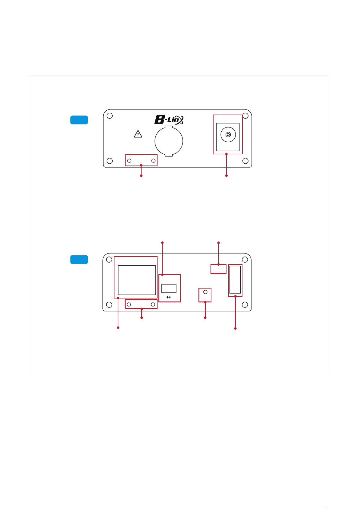
1.4. Hardware Overview
Right
Left
56V DC
Bracket
NO ANALOG
CAMERA
ETHERNET
PoE-ON
Data-Link
Join-Link
Power
PoE
Bracket
Join
ON OFF
Bracket Hole
Bracket Hole
RJ45
Join Button
Status LED Indicator
DC Power Jack
PoE ON/OFF Switch
(Transmitter model
only)
PoE-ON (Transmitter model only)
PD-AUX (Receiver model only)
Quick Installation Guide — 5
1.5. Product Installation Guide
1. Set the IP address on the camera following the instruction manual of the camera.
hIf the camera IP is automatically assigned (DHCP, etc.), there is no need to set the camera IP separately.
2. Connect BNC of the coaxial cable to each Transmitter/Receiver.
3. Connect 56V DC power to Transmitter/Receiver first and then to AC outlet.
recommeded to use 56VDC Power supply on Receiver. When using both PoE switch Device and
hReceiver can be powered by PoE Switch Device (PoE+ PD Supported) but for safe working, it power supply
at the same time, power supply works preferentially.
hIn case of 7W camera, the device supports long distance PoE transmission up to 1,200m over RG6 coaxial
cable.
PoE transmission distance can be varied depending on cable type and Camera’s
power consumption(W).
4. When they are connected without any problem, Power / Join Link LED are on.
5. Adhere the brackets in the package to Transmitter/Receiver and then fix up the products.
6. Connect the UTP(LAN) cable between Receiver and NVR first and then between Transmitter and camera.
7. Turn on the PoE switch on Transmitter for PoE IP camera and if the camera is powered by a separate power
source (not powered by PoE output feature of the Transmitter), turn off the PoE switch on Transmitter.
hBoth Transmitter/Receiver send data and power together via BNC connector. Receiver does not have
PoE
support so that it can send data only via RJ45.
8. Ping test is recommended to confirm the whole network after installation.
9. Check the video signal on the monitor.
1.6. Product Application
AC/DC
Adapter(12V)
Non-PoE IP
Camera
Coaxial Cable
Coaxial Cable
10/100 Ethernet
10/100 Ethernet
Po E
Receiver
56V DC/1.2A
Power Supply
NVR
Transmitter Receiver
Transmitter
Po E
Camera
PoE Switch
PoE : OFF
PoE : ON
PoE
In put Power
DC Adapter
In put Power
NOTE:
- To avoid damage of products do not connect Transmitter RJ45 PoE Out to a PoE Switch!
- Joining function by hardware is only available between Transmitter/Receiver or
Transeiver devices except camera.

1.7. Network Password Change
All EPoC products have the same network password on factory default to support plug & play between EPoC
products. In case of multiple 1:1 connections, It is possible to avoid network interference by setting password
of each group.
1. Basic connection
-Prepare a short coaxial cable for convenience.
-Connect EPoC products and power adapter.
2. Unjoin : removing the password
-Push the join button for 15 seconds. BNC Join LED turns off.
-Push the join button for 15 seconds on the other side.
3. Join : making new password
-After unjoining, push the join button for 1 or 2 seconds.
PWR LED turns off and on, and then BNC Join LED turns on.
-Push the join button for 3 seconds on the other side.
-After PWR LED is on, BNC Join LED on both side are flickering and the network is working again.
4. Repeat above 1~3 for the other groups.
hNew and random password is automatically assigned and it can not be restored to the factory default
password.
Group A
Group C
Group B
Transmitter
Transmitter
Transmitter
AC/DC Adapter (56V) Receiver
AC/DC Adapter (56V) Receiver
AC/DC Adapter (56V) Receiver
Quick Installation Guide — 6
NOTE:
-To avoid damage of products do not connect Transmitter RJ45 PoE Out to a PoE Switch!
-Joining function by hardware is only available between Transmitter/Receiver or
Transeiver devices except camera.

Quick Installation Guide — 7
1.8. LED Indicators
Indicator Color Function
PoE-ON PoE Output Status (Transmitter model only)
PD-AUX PoE Input Status (Receiver model only)
Data-Link Blinks when transmitting Ethernet data
Join-Link EPoC products connected
Power 56VDC or PoE Input connected
1.9. Specification
Model Transmitter Receiver
Interface
Coax 1 x 75Ω BNC (Female) - Ethernet over Coax (B-LinX)
Ethernet 1 x RJ45 - 10/100 Base-T with Auto-detect MDIX
Transmission Rate 95Mbps Full Duplex
Transmission
Distance
Ethernet up to 2.4Km(RG-6)
PoE (PoC) up to 1.2Km (RG-6 / 7W camera)
LED
Indication
Ethernet 1 x Data-Link (Yellow)
EPoC 1 x Join-Link (Green)
Power 1 x Power On(Amber)
PoE 1 x PoE Out (Red)
Encryption 128-bit AES
Power
Input B-Linx or DC12V~57V PoE Switch or DC12V~57V
PoE Output Extra PoE up to 60W PoE Not Supported
PoC Only
Mechanical
Dimension 82.4(L) x 61.6(W) x 24(H)mm
Weight 77g
Environment
Operating Temp -20 ~ 60°C
Storage Temp -30 ~ 80°C
Relative Humidity 10% ~ 90%
Compliance
Certification FCC, CE, KC, RoHS
Surge Protection IEC 61000-4-5 4kV(1.2 / 50us), 2kA(8 / 20us)
Optional Accessories 56VDC / 1.2A External Power Supply

Quick Installation Guide — 8
1.10. Caution
•Please install the device following the installation guide.
•Do not touch the device and cable with wet hands.
•Keep away from moisture and shock.
•Do not install near any heat sources such as radiators, heat registers, stoves or other apparatus that produce
heat.
•Indoor use only.
•Do not use for other purposes. (i. e. Connecting analog camera to BNC connector)
•Do not disassemble or modify this device.
•Do not put any sticker or paint on it.
•If this device is defective or malfunctioning, please unplug the power adapter immediately and contact dealer or
service center.
•Use only rated 56V power adapter specified by the manufacturer. Connect DC power to EPoC Extender first and
then to AC outlet.
1.11. Warranty
•This device has passed the quality control and product inspection.
•Please install and use according to the installation guide.
•The warranty period for this product is 24 months from the date of purchase.
•Any damages or breakage from user’s abuse, accident, modification or natural disasters will not be covered
manufacturer’s warranty.
Pre-field verification — 9
2. Pre-field verification
2.1. Check transmission line
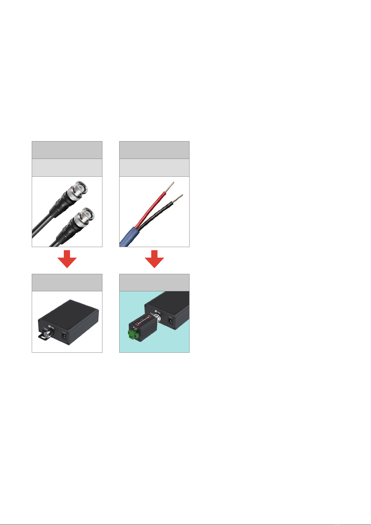
2.1.1. Transmission line type
█ EPoC (Ethernet over Coax) Applicable
Coaxial cable
3C, 5C, 7C, 10C, RG58, RG59,
RG6, RG11, KX6,
KX100, etc.
Ethernet over
Coax Extender
2-Wire
UTP cable
EPoC Extender +
IAM-4MU1001M0A
Pre-field verification — 10
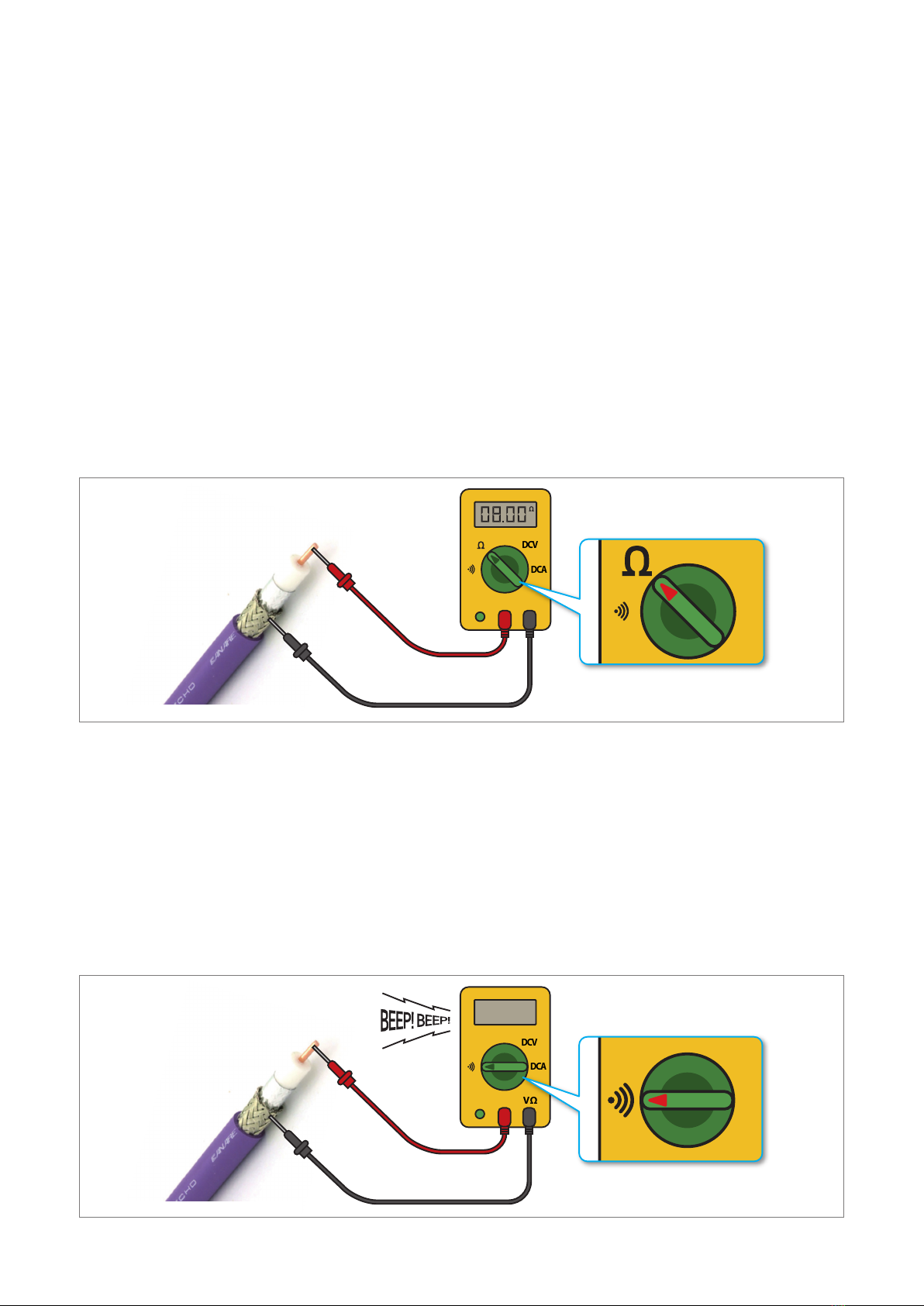
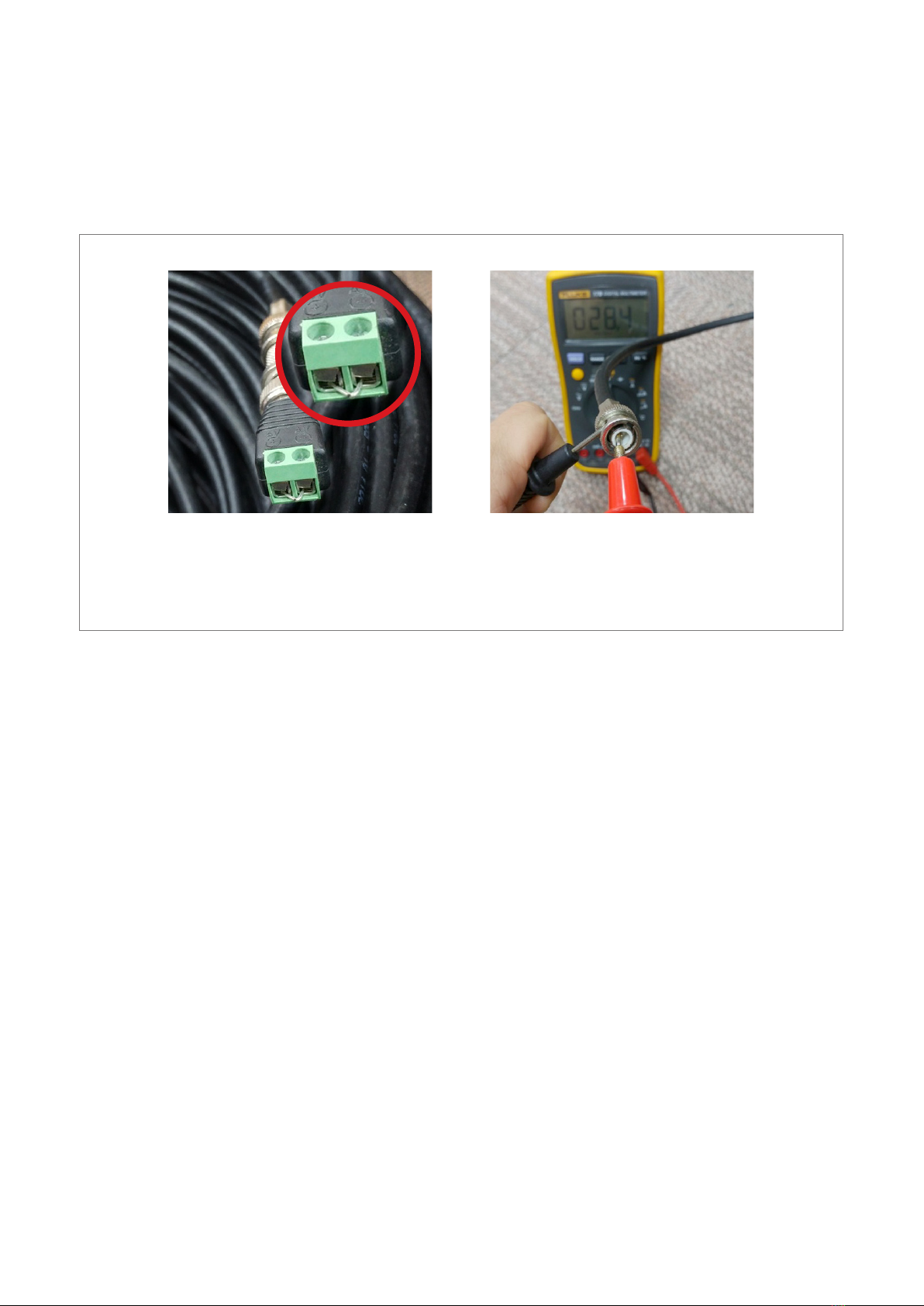
2.1.2. Check whether the cable is disconnected / shorted
█ Test cable opens
1. Make a short the conductor and shield of the one side of the coax.
2.
Take the testing probe and connect its cords to the specific ends of multimeter (red positive into the ‘+’ marked jack
and black negative into the ‘COM’ jack) and Set the measurement type dial of the multimeter to Ω.
3. Touch one of the leads to the outer metal part of the BNC and the second to the center pin on the another side and
check the value.
4. If the value is significantly high such as Mega Ohm, it means the cable might be open.
5. If the value is lower than the expected loop resistance value, the cable might be shorted. (Normal loop resistance of
the cable in case of RG59 is about 8~10 Ω / 100 meter)
OFF DCV
DCA
A
COM
VΩ
OFF DCV
DCA
COM
AVΩ
█ Test for shorted or open
1. Make both ends of the coax free by disconnecting it from the device
2. Take the testing probe and connect its cords to the specific ends of multimeter (red positive into the ‘+’ marked
jack and black negative into the ‘COM’ jack) and Set the measurement type dial of the multimeter to continuity test.
3. Touch one of the leads to the outer metal part of the BNC and the second to the center pin. If you don’t hear any
sound, then it means the coax is not shorted.
OFF DCV
DCA
A
COM
Ω
VΩ
OFF DCV
DCA
A
COM
Ω
VΩ

Pre-field verification — 11
█ Cable Connection Precautions
•Be sure to use dedicated connector when connecting cables.
•It is not recommended to mix different types of cables.
-When 50Ω and 75Ω cable are used in combination or 50Ω BNC is applied to 75Ω cable, the impedance between
the lines is unmatched and this could affect performance of the device.

Pre-field verification — 12
2.1.3. Cable distance
Ethernet over Coax (EPoC) products have different Ethernet and PoE transmission distance depending on
the product lineup.
Check the maximum transmission distance between the transmitter and receiver in advance.
█ PoE distance by available wattage to end-device (e.g. Single port product)
Camera power
consumption (Watt)
3C-2V / RG-59, meter
(Bare Copper Cable)
5C-HFBT / RG-6, meter
(Bare Copper Cable)
3 900m 1800m
7 750m 1200m
10 550m 900m
12 450m 750m
15 350m 600m
20 300m 500m
25 200m 350m
30 150m 250m
40 60m 100m
50 40m 80m
60 25m 50m
•The above distances are calculated value and the result may vary depending on the cable and connector quality.
•The above mentioned transmission distance is a condition when using single port device with DC 56V
/1.2A power supply.
•Cable Loop Resistance is 18Ω / 200m with RG-59 and 10Ω / 200m with RG-6 condition.
•Above result is the value when using Bare Copper Cable and in case of the Copper covered steel cable, the distance
can be reduced by about 40 ~ 50% compared with Bare Copper Cable.
Pre-field verification — 13
2.1.4. Identify loop resistance
•By measuring the loop resistance of the cable, it is possible to check the condition and the quality of the cable
used for power transmission function of the EPoC device in advance.
1. Make a short the conductor and
shield on one side.
2. Measure the resistance (Ω) of the
conductor and shield on the other
side.
•In case of Copper-covered steel cable, the cable loop resistance can be significantly increased and It is strongly
recommended to check the cable loop resistance before installation because it can greatly affect the distance
performance of the devices
•The PoE transmission distance specified on the installation guide is the value when using RG-6 Coaxial cable with
10Ω or less / 200 meter.
•If accurate loop resistance is not measured, such as measuring KΩ, MΩ, etc. as result, check if the cable or BNC is
shorted or if there's power leakage on cable.

Pre-field verification — 14
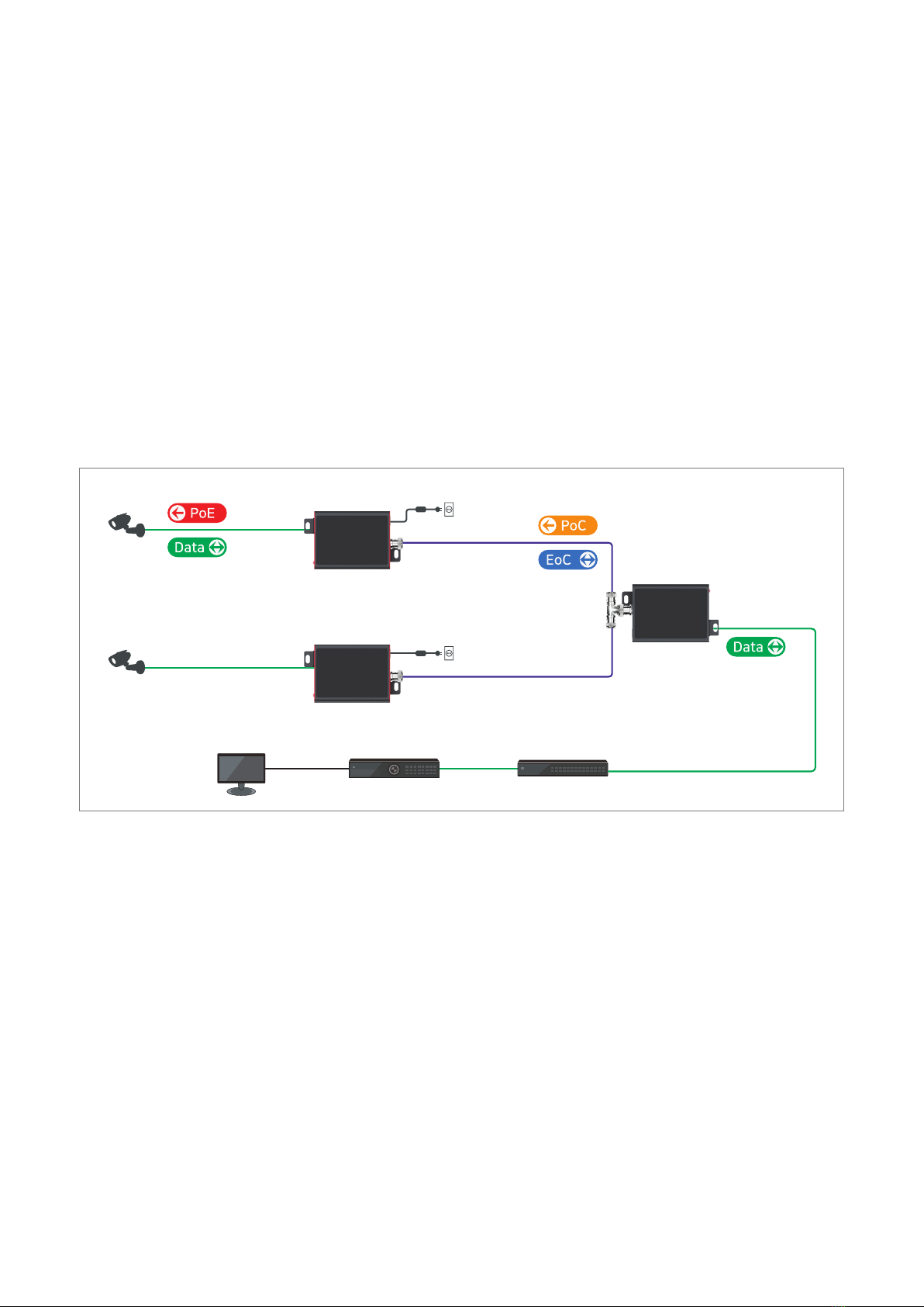
2.2. Check grounding and potential difference
EPoC equipment is basically grounded through the power cord of the adapter, so there is no need to ground
separately.
However, EPoC equipment supports PoC (Power Over Coax) function and the transmitter is powered by the power
source connected to the receiver and the end-device is powered by the transmitter through the PoE output feature.
At this time, if there is a potential difference between the end-device and the transmitter, the transmitter may not
recognize the PD (Powered Device) of the end-device correctly, and the PoE output function of the transmitter may
not work properly.
Therefore, it is necessary to make sure that the end-device is normally grounded, and that there's the potential
difference between the end-device and transmitter.
Pre-field verification — 15
2.4. Power supply availability
EPoC equipment supports PoC (Power over Coax), so that the transmitter and the end-device (e.g. camera) are
powered by receiver.
When installing multiple cameras over one cable with daisy chain configuration or PTZ camera with high power
consumption, it is possible to configure by putting an additional power adapter (48 ~ 57VDC) on the transmitter.
█ Examples of using additional adapters
•When installing two cameras with high power consumption such as 30W by 2:1 Daisy chaining, two power adapters
of 56VDC /1.2A can be applied on the transmitters and the maximum 120W power is supplied throughout the
whole range.
•The power adapter can be applied to transmitter or receiver or both transmitter and receiver simultaneously.
56V DC/1.2A Power Supply
Network Switch
NVR
Cat. 5e
100m
Receiver
100m
Cat.5e
600m
RG-6 Coaxial cable
100m
Cat.5e
600m
RG-6 Coaxial cable
30Watt
PoE Camera
30Watt
PoE Camera
Transmitter
56V DC/1.2A
Power Supply
Transmitter
2.5. Site environment review
•Check the environment in which EPoC device is installed.
•The cable between the EPoC devices must be installed apart from high-voltage power cable.
•In environments where cross-talking or signal interference occurs, separate settings may be required, such as
network grouping (See how to set Joining).
•In environments where power noise occurs (e.g. Installation on elevator), it is necessary to use a model
specifically designed to prevent noise.
•EPoC devices are for Indoor Use and must be installed in a separate watertight enclosure when installed
outdoors.
•Check that the environment is suitable for the operating temperature and operating humidity of the equipment.
NOTE:
-To avoid damage of products do not connect Transmitter RJ45 PoE Out to a PoE Switch!
-Joining function by hardware is only available between Transmit ter/Receiver or
Transeiver devices except camera.

Equipment Installation Guide — 16
3. Equipment Installation Guide
3.1. Selection of installation equipment
3.1.1. EPoC Solution Network Security
█ IP Video Surveillance
EPoC devices allow the coaxial cables from existing analogue CCTV system to be re-used for network
camera connection.
Reusing existing coax for IP cameras can cut installation costs and save installation time significantly.
EPoC devices will even provide 60W power over existing cable and outputs PoE to cameras, it would be
sufficient power for up to 4 cameras operation in DAISY CHAIN CONFIGURATION.
Coaxial cable
AC / DC Adapter(12V)
DVR
D1 : 640 X 480
Analog Camera
Coaxial cable
10/100 Ethernet
PoE
NVR
Full HD : 1920 x 1080
PoE IP Camera
Receiver
Transmitter
AC/DC Adapter (56V)
NOTE:
-To avoid damage of products do not connect Transmitter RJ45 PoE Out to a PoE Switch!
-Joining function by hardware is only available between Transmit ter/Receiver or
Transeiver devices except camera.

Equipment Installation Guide — 17
█ Network Extension
Extended distance with PoE
EPoC devices provides high speed & long distance Ethernet connectivity via various cables such as Coax, UTP 4
pair cable, even UTP 1 pair cable, etc. With long distance transmission feature, EPoC devices make to overcome
100 distance limitation of the general network configuration in a simple and easy way.
Also, EPoC devices will even provide PoC (Power over Cable) and PoE up to 60W to the end device, it is useful
when installing PoE powered devices like PoE Wireless APs and cost saving solution without power wiring work
for the network devices.
Wifi AP
PoE, PoE+
MAX 60W
Existing Cable ( Coax, UTP, COM,Power line, etc)
Data + Power
Fiber optic cable
Wifi AP
PoE, PoE+ Power Cable
NOTE:
-To avoid damage of products do not connect Transmitter RJ45 PoE Out to a PoE Switch!
-Joining function by hardware is only available between Transmit ter/Receiver or
Transeiver devices except camera.

Equipment Installation Guide — 18
3.2. Transmission rate / PoE output
•Transmission rate(Mbps) by product configuration
Daisy Chain
Distance
1:1 1:2 1:3 1:4 1:5 1:6 1:7 1:8
200m 95 47 31 23 18 15 12 10
600m 95 47 31 23 18 14 11
1,200m 95 43 26 18 13 10
1,800m 95 41 23 15 10
2,400m 50 18
•PoE output(W) by product configuration
Daisy Chain
Distance
1:1 1:2 1:3 1:4 1:5 1:6 1:7 1:8
50m 40 19 12 8 6
200m 35 16 10 7 5
300m 27 12 7 5
400m 22 10 6
500m 17 7
700m 11

Equipment Installation Guide — 19
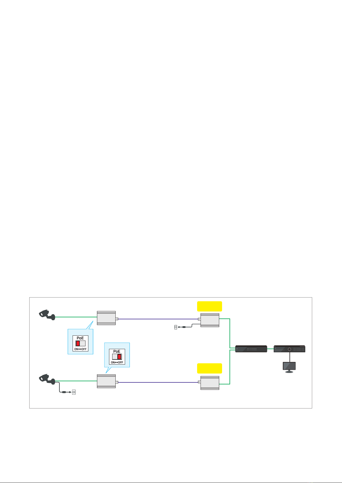
3.3. PoE On / Off Setting
EPoC transmitter has PoE On / Off switch. When connecting with non-PoE equipment, PoE The switch must be set
to Off.
The factory default setting of the PoE On / Off switch is OFF. Therefore, when installing transmitter with PoE devices,
the PoE switch must be set to On for power supply.
EPoC Extender is designed to be used as transceiver and when using these device as receiver with non-PoE
equipment, the PoE switch must be set to OFF.
•PoE Camera Application (PoE Switch On)
95Mbps
AC/DC Adapter(12V)
Non-PoE IP Camera
PoE IP Camera
NVR
NVR
AC/DC Adapter (56V)
Rx
Tx
95Mbps
AC/DC Adapter (56V)
Rx
Tx
•Non-PoE camera application (adapter used, PoE switch off)
95Mbps
AC/DC Adapter(12V)
Non-PoE IP Camera
PoE IP Camera
NVR
NVR
AC/DC Adapter (56V)
Rx
Tx
95Mbps
AC/DC Adapter (56V)
Rx
Tx
NOTE:
-To avoid damage of products do not connect Transmitter RJ45 PoE Out to a PoE Switch!
-Joining function by hardware is only available between Transmit ter/Receiver or
Transeiver devices except camera.
Other manuals for IAM-6MC1001MTA
1
This manual suits for next models
3
Table of contents
Other Eneo Receiver manuals

Popular Receiver manuals by other brands


Harman Kardon
Harman Kardon AVR 247 Worksheet

Silca
Silca Air4 Home Translation of the original instructions

Inovonics
Inovonics EchoStream EE4216MR Installation and operation manual

Pioneer
Pioneer X-HM31DAB-k operating instructions

Dual
Dual XDVD269BT Installation & owner's manual

Hyundai
Hyundai DVBT 210 user manual