Ener-G+ HIB-2000 User manual
1
year/an
warranty
garantie
Modèle/Model: HIB-2000
BATHROOM WALL-MOUNTED FAN
HEATER
Operators’ Manual p. 1
AÉROCONVECTEUR MURAL POUR
SALLE DE BAINS
Guide de l'utilisateur p. 11

...................................................2
.....................................................................................3
.............................................................4
.................................................................5
.............................................................................................6
.................................................................8
..............................................................................................9
............................................................................................10
.........................................................................11
• IMPORTANT SAFETY INSTRUCTIONS
• SPECIFICATIONS
• INSTALLATION INSTRUCTIONS
• ELECTRICAL CONNECTIONS
• OPERATION
• MAINTENANCE & CLEANING
• WARRANTY
• PARTS LIST
• SCHEMATIC DRAWING
1

2
IMPORTANT SAFETY INSTRUCTIONS
• Read all instructions before using this fan heater. SAVE THESE INSTRUCTIONS!
• In Canada, the installation of this product must be carried out by a certified master
electrician.
Before installing and operating this product, the owner and/or installer must read,
understand and follow these instructions and keep them handy for future reference. If
these instructions are not respected, the warranty will be considered null & void and
the manufacturer deems no further responsibility for this product.
1.This product may present a risk of fire if it is not properly installed & maintained as
per the instruction manual.
2.Not following these instructions could lead to serious injury causing bodily harm,
property damage, and electrocutions resulting in death.
3.This product must be installed by a certified master electrician, in accordance with
all local & national building codes.
4.It is the user’s responsibility to assure that materials such as blankets, towels, beds,
furniture, laundry baskets, clothing, etc. do not come in contact with, nor come
within 4 inches (10 centimetres) of the heater. Failure to follow this warning could
lead to fire.
5.Never obstruct the airflow locations, i.e, air intake and exhaust. This could cause the
product to overheat and lead to fire.
6.Certain locations are dustier than others. It is therefore the user’s responsibility to
determine whether or not the product must be cleaned based on dirt build-up on the
unit’s air intake & exhaust, as well as inside the unit. Accumulated dust and dirt
could cause components to become defective, which could lead to fire.
7.If the installer and/or user modifies this product in any way, he/she will be held
responsible for any damages resulting from this modification.
8.Make sure that the heating capacity of the unit is sufficient for the size of room it is
intended to heat. If the capacity is insufficient, the heater will work constantly,
causing it to discolour (turn yellow) and/or prematurely deteriorate.
Suggested calculation to determine heating requirements :
10 watts / square foot (0.3 m2) based on a ceiling height of 8 feet (2.44 meters).
1.2 watts / cubic foot (0.3 m3) for locations where the ceiling height exceeds 8 feet
(2.44 meters).
9.An activated thermal protection (overheat sensor) warns that the heater has been
subjected to abnormal conditions. If this occurs, stop using the heater immediately
and bring it to an authorized service centre for inspection and repair.
3
IMPORTANT SAFETY INSTRUCTIONS
10.A heater contains components that become hot and produce electrical sparks. Do
not operate it in areas where gasoline, paint, or flammable liquids are used or
stored.
11.This unit must be permanently secured to one of the bathroom walls and must only
be used to heat the room where it is installed.
12.Make sure the main power supply complies with the rating plate: 240 V AC, 60 Hz.
13.Never let children play with the unit. Caution! When the unit is on, the air outlet grille
can reach very high temperatures (more than 80 °C).
14.Never use this unit within arm’s reach while in the shower, the bathtub or near a
sink. Never let water enter the bathroom fan heater which will lead to electric shock!
15.Never secure the unit to walls made of synthetic materials.
16.This heater must always be installed vertically on a wall.
SPECIFICATIONS
240V AC, 60Hz
8.14 lbs (3.7 kg)
13.78” x 22.6” x 6.7”
(35 x 57.5 x17 cm)
This fan heater is intended for permanent wall-mounting with the provided screws.
The heater has a thermal cut-off protection. If the thermal cut-off protection trips, switch
off the power. The unit should reset automatically after 10 minutes. If the thermal cut-off
protection trips again, determine the reason for overheating.
Model HIB-2000
Voltage
Watts
Amps
1 200/2 000 W
8.3 Amp
Net Weight
Dimensions
(W x H x D)
INSTALLATION INSTRUCTIONS
4
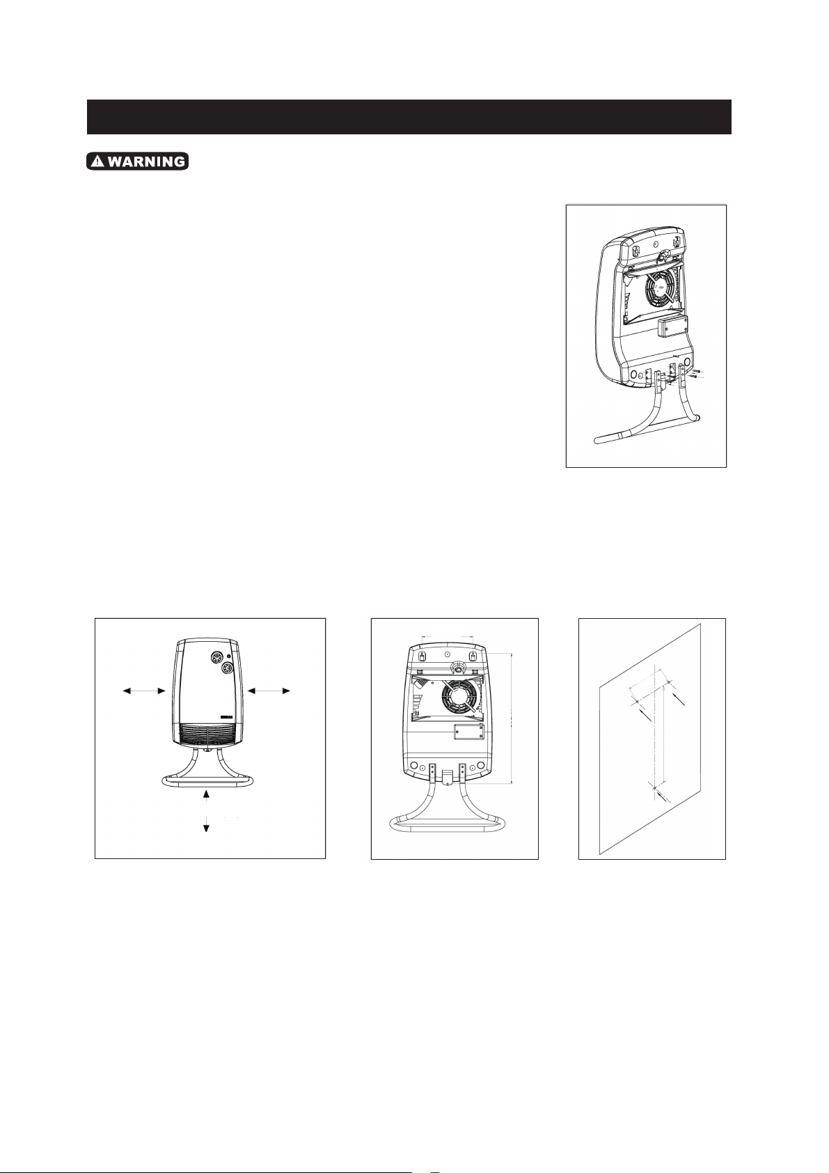
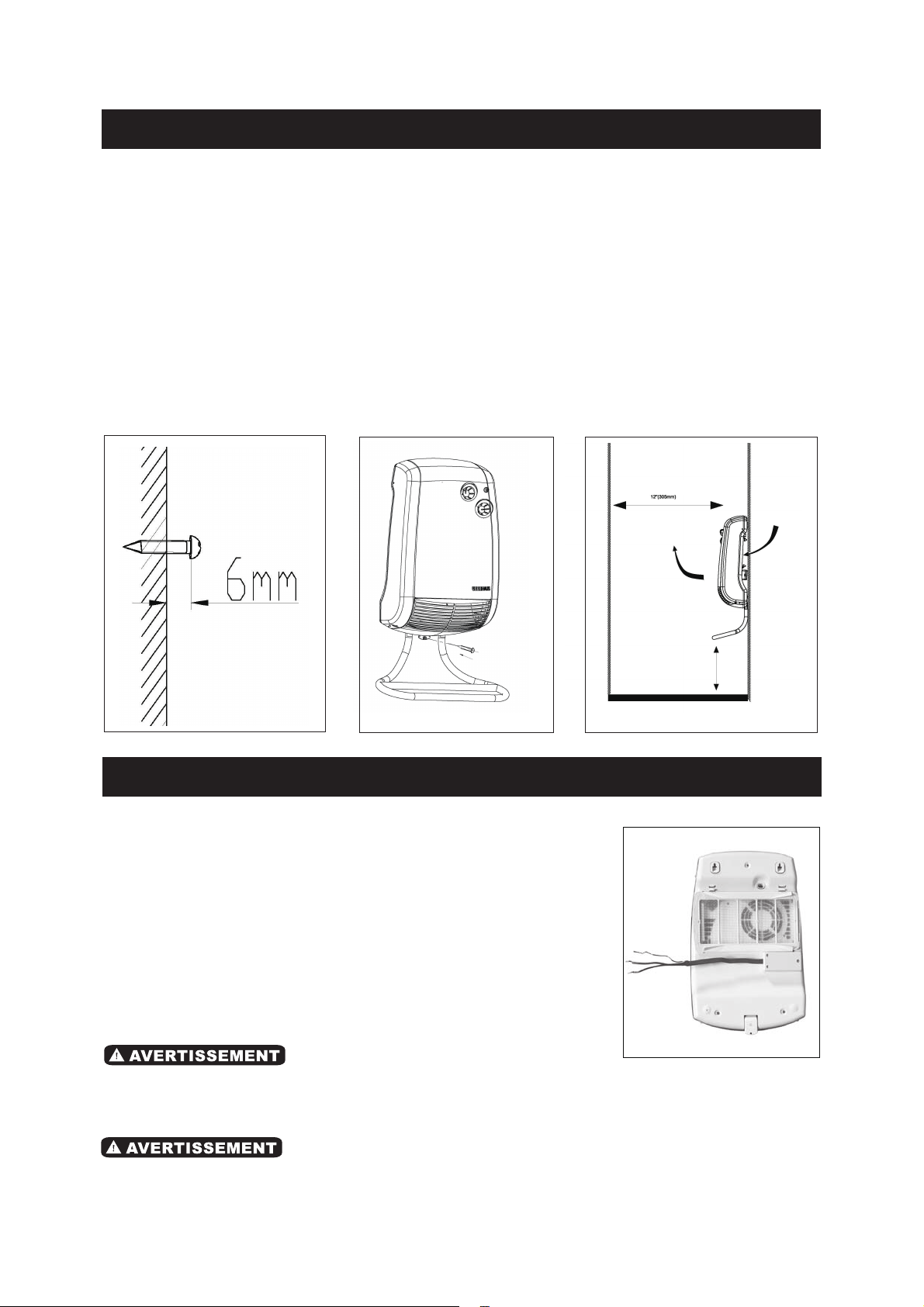
4. Insert the two top screws provided,leaving a gap of 1/4" (6mm) between the screw
head and the wall.(Fig.5)
5. Hang the unit on the installed screws, while holding it securely in your hands.
WALL MOUNTING
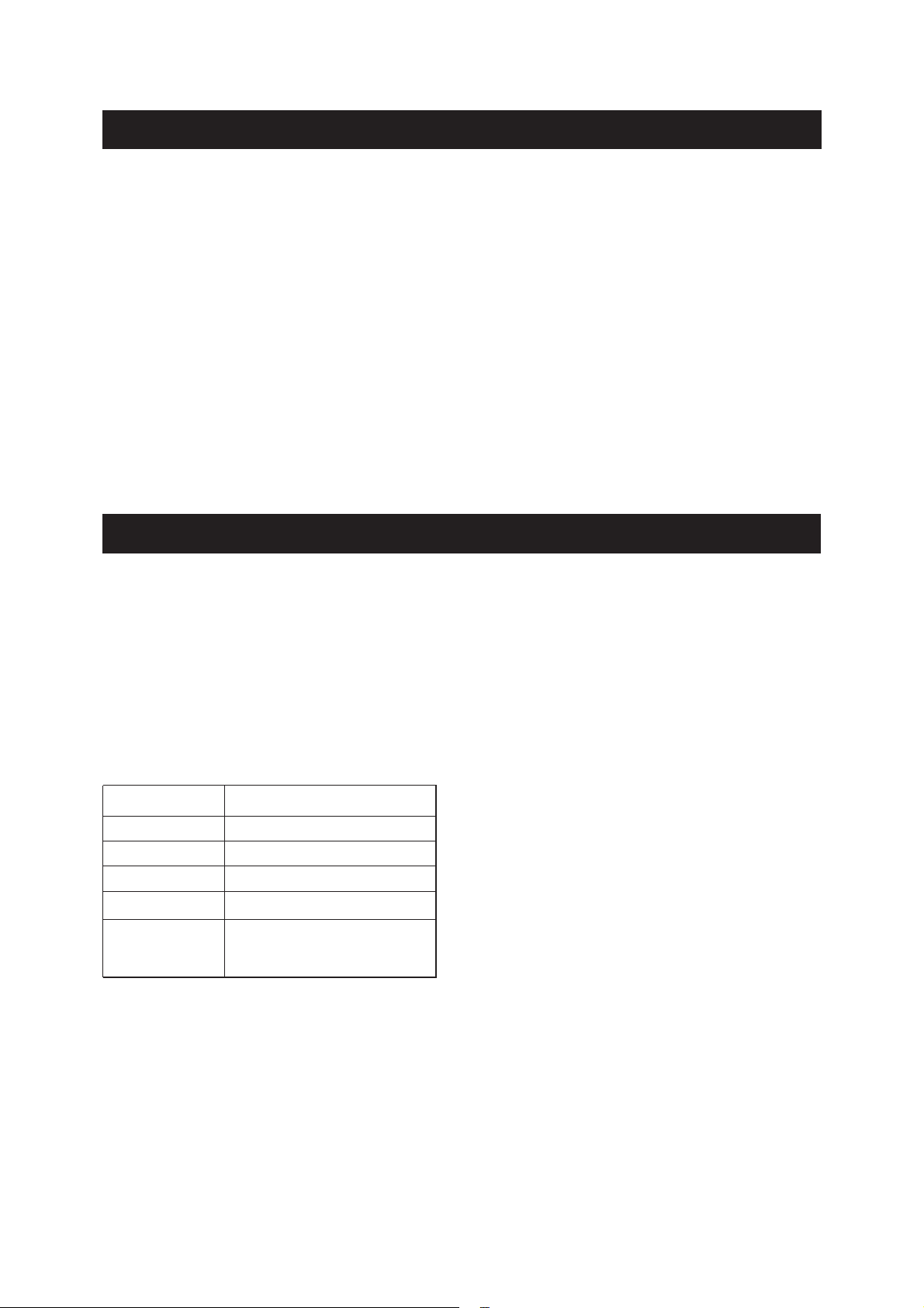
1. The unit must be secured to the wall 24in (600mm) away from the floor and 12 in
(305mm) from adjacent walls (Fig.2). The unit can't be covered or hidden by a door.
2. Drill three holes with a diameter slightly smaller than the one for the plastic pins
provided.
3. Insert the pins.(Fig.3 and Fig.4)
TOOLS REQUIRED (not included)
• Electric drill
• Phillips (cross-head) screwdriver
• Measuring tape
To fix the towel rack (Fig.1)
1.Place both ends of the towel rack into the slots at
the back of unit and align the holes.
2.Screw the towel rack and unit together with four
screws (supplied).
Fig.2
Fig.1
Fig.3 Fig.4
Minimum
12” (305mm)
Minimum
12” (305mm)
Minimum
24” (600mm)
6” (153mm)
15 3/8” (319mm)
15 3/8” (319mm)
6” (153mm)
Wall Wall
Floor
• Installation must be performed in accordance with the requirements of the CEC by
authorized personnel only.
5
ELECTRICAL CONNECTIONS
INSTALLATION INSTRUCTIONS
Fig.8
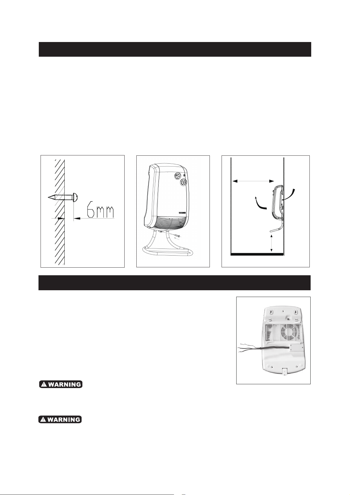
• Make the electrical connections inside the junction box
located at the back of the unit (Fig.8).
• Installation of this product must be made in
accordance with all national and local building codes.
• The electrical connections must be made with a
12-gauge 2-conductor wire complete with ground.
CAUTION! BEFORE LETTING GO OF THE UNIT, CHECK THAT IT IS SECURELY
HUNG ON THE TWO SCREWS
6. Secure the unit with the third screw at the bottom .(Fig.6)
The Fig.7 on the right indicates the airflow generated by the heater. This air corridor
must remain clear in order to allow good air circulation and to ensure that the unit
operates efficently. Leave a space of at least 12 in (305mm) from the front and 24 in
(600mm) from the floor.
Do not install the heater below an electrical convenience outlet.
• The heater must be installed by a certified electrician and in accordance with the local
and national building codes.
• This fan heater is to be used on a 240 V AC power supply and grounded outlets.
Fig.5 Fig.6 Fig.7
Minimum
24” (600mm)
Minimum
12” (305mm)
Air outlet Air intake
OPERATION
6
ELECTRICAL CONNECTIONS
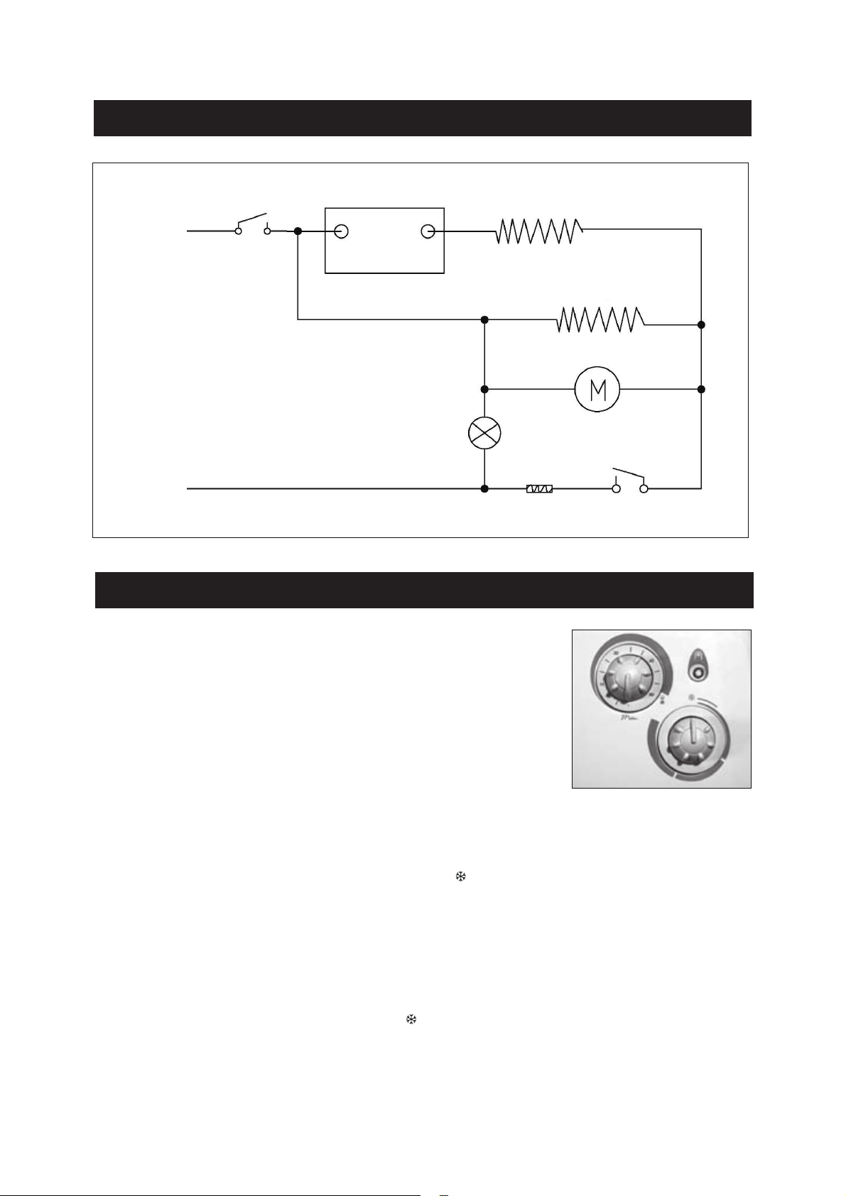
The fan heater has two knobs, one for the 60-minute timer
and one for the thermostat.
THE UNIT HAS TWO OPERATING MODES:
ROOM WARM-UP WITH TEMPERATURE CONTROL
From the position marked “ “, turn the thermostat knob clockwise until a clicking noise
is heard; the unit is turned on at a power of 1200 W and the warning light comes on.
The thermostat maintains the required room temperature by automatically turning on
and off the fan heater. The more you turn the knob clockwise, the higher the constant
temperature will be. The thermostat maximum setting is about 35 °C and the minimum
setting “ “ is about 5 °C.
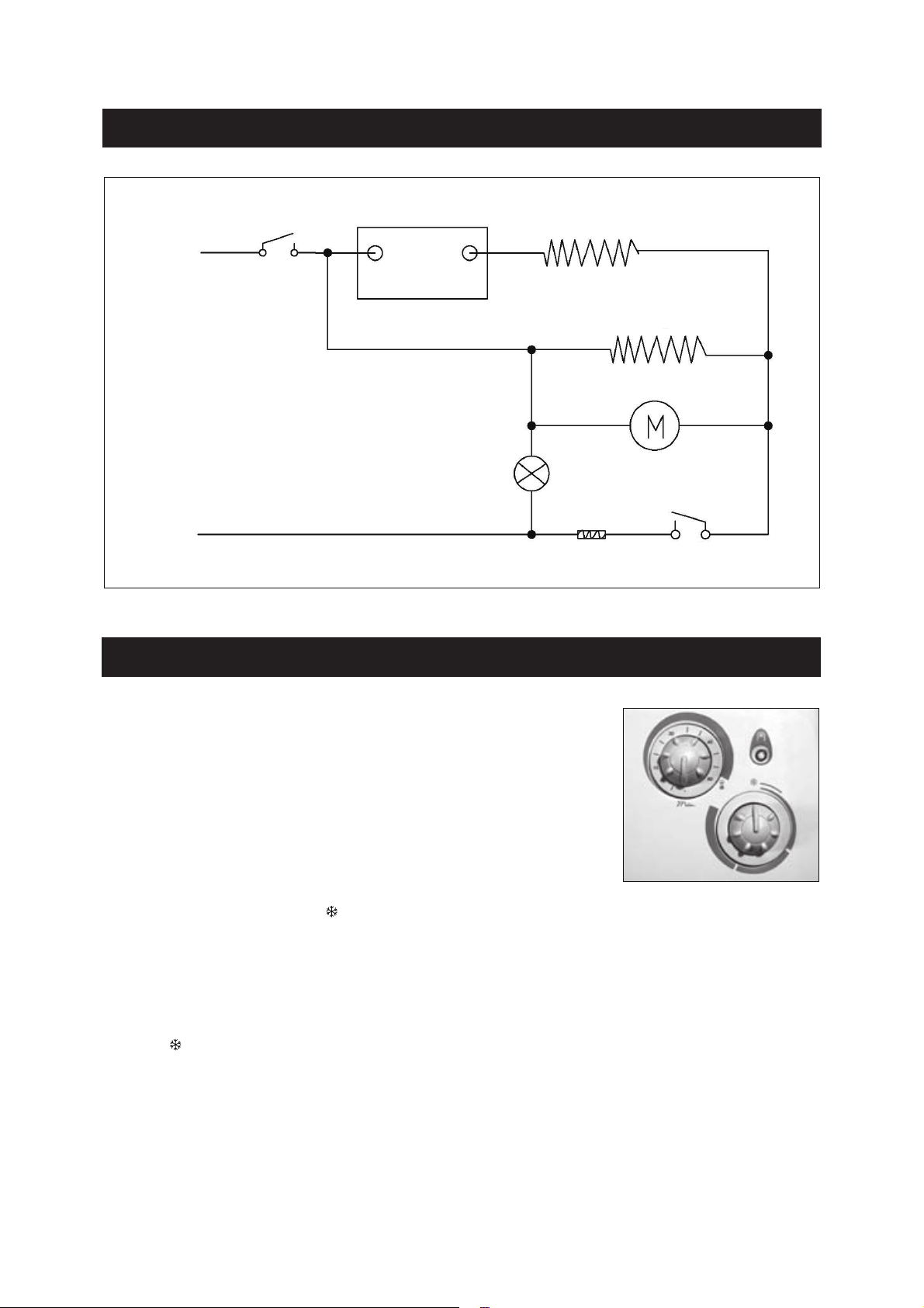
THERMOSTAT
TIMER
HEATING ELEMENT
800W
1 200W
HEATING ELEMENT
INDICATOR LIGHT
FUSE THERMAL CUT-OFF
PROTECTION
MOTOR
L1
L2

OPERATION
7
Setting the thermostat:
With a room temperature above 35 °C, it is normal for the thermostat to not turn on the
fan heater, even at the maximum setting.
With a room temperature too low (under 5 °C), it is normal for the thermostat to
maintain the unit on, even at the minimum setting.
To optimize thermostat usage:
• Set the thermostat to the maximum setting and operate the unit until a comfortable
temperature is reached;
• Then, turn the thermostat knob counter-clockwise until a click is heard (the unit is
turned off);
• Slightly turn (just a little) the thermostat knob clockwise; At this setting, the thermostat
maintains the chosen room temperature.
QUICK ROOM WARM-UP
With the room temperature set at the required level, turn the timer knob to select the
required operating time. The unit operates at 2000 W for the set time to quickly heat
the room and then maintains the room temperature set by the thermostat at a power of
1200 W.
SAFETY IN CASE OF ABNORMAL OPERATION
In the event the unit overheats, the built-in protection system automatically deactivates
the heating elements and the motor, effectively stopping the fan heater operation. In
this case, the unit is inactive, but the warning lamp is on.
In this case, follow these instructions:
• Turn off the fan heater and let it cool for about 15-20 minutes. It is imperative to set
the thermostat and the timer to the “OFF” position in order to re-start it;
• Check if the dust filter is blocked and if so, clean and reinstall it;
• Locate potential overheating factors (i.e. obstruction in front of the air outlet or inlet
grille, unusual dirt accumulation, etc.);
• Turn the fan heater on again and check for proper operation. If you cannot get your
unit to work, contact Customer service at 1-866-967-7333.

8
Maintenance
1) Always turn off the heater before cleaning.
2) Do not knock against or rub the heater to avoid damaging the exterior coating, which
may allow rust to appear.
3) Never immerse the heater in water for cleaning.
• To reduce the risk of fire or electric shock, always switch off the unit and wait 10
minutes to allow it to cool before attempting any maintenance or cleaning. It is
recommended that the heater be cleaned periodically, in order to avoid dust blocking
the grill or ventilation.
MAINTENANCE & CLEANING
Cleaning
Wipe the unit with a soft damp cloth. Do not use abrasive
cleaners or spray liquids on the unit surfaces.
Your unit has a filter protecting the heating elements
against dust and dirt.
The filter can be removed and inserted from the right or
the left side.
For optimal operation, we recommend cleaning the filter once every 2 months and
making sure to reinstall it properly on the unit.
Regularly vacuum the front grille to remove the dust. Accumulated dust and lint at the
air outlet can reduce the unit’s performance and even damage it. To clean the unit, use
a slightly damp cloth. Note that cigarette smoke can cause unit's color to fade, despite
regular cleaning.
Note:
• It is possible that the unit surface may discolor (yellow) over time due to dust or
cigarette smoke. This is normal and not a manufacturing defect.

9
WARRANTY
LIMITED ONE (1) YEAR WARRANTY
This product is guaranteed against all manufactured faults and defects for a period of
one (1) year from the date of purchase. If your unit has a manufactured fault or defect,
return the unit to the original point of purchase (store) with your proof of purchase on
hand or call our customer service department at 1-866-967-7333.
Important notes: Any damage caused by an accident or an abusive usage is NOT
covered under warranty. We also decline all responsibility concerning indirect or
consecutive damages. In certain Canadian provinces, it is not permitted to limit indirect
or consecutive damages. Therefore it is possible these limitations are not applicable to
you. This warranty gives you specific legal rights. You may also have other legal rights
which vary from one province to another.
CUSTOMER SERVICE: 1-866-967-7333 ext 227
• Repairs should be made by an authorized repair centre. Opening this heater could
invalidate your warranty.
Note:
• Due to continuous product improvement, we reserve the right to change the product
specifications without prior notice.
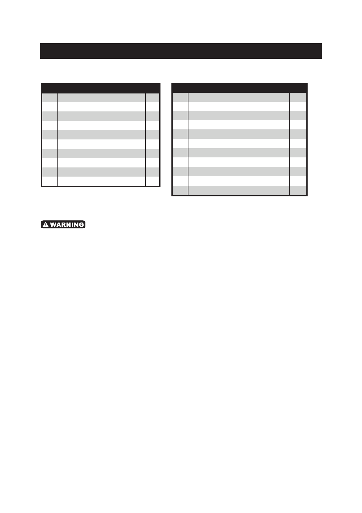
PARTS LIST
NO DESCRIPTION QTY
1
2
3
4
5
6
7
8
9
10
1
1
2
2
1
1
1
1
1
1
Panel
Fan Cover
Knob Decorative cover
Knob
Switch Plate
Timer
Thernostat
Fan Wheel
Base
Base Plate
NO DESCRIPTION
11
12
13
14
15
16
17
18
19
20
21
1
1
2
1
1
1
1
2
1
1
1
Back Filter
Junction Box (up&down)
Decorative cover
Fan Nets
Heating Element
Motor
Baffle
Gasket
Electronic Wire
Indicator Light
Towel Tube
QTY
10
Please refer to the Schematic Drawing, on the following page.

11
SCHEMATIC DRAWING / SCHÉMA
12
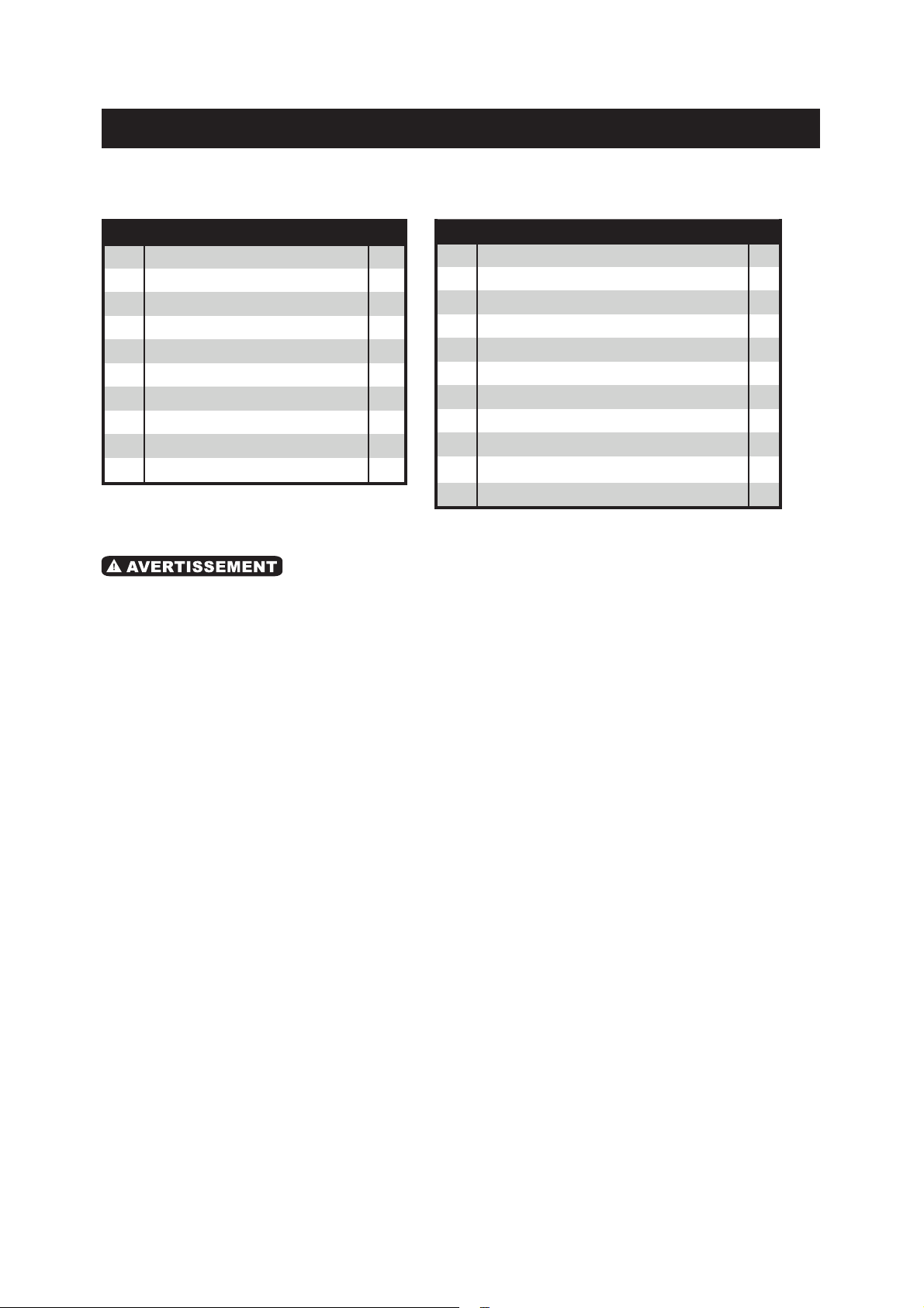
LISTE DES PIÈCES
NO DESCRIPTION QTY
1
2
3
4
5
6
7
8
9
10
1
1
2
2
1
1
1
1
1
1
Panneau
Couvercle de ventilateur
Couvercle du bouton décoratif
Bouton
Plaque d'interrupteur
Minuterie
Thernostat
Roue du ventilateur
Base
Plaque de base
NO DESCRIPTION
11
12
13
14
15
16
17
18
19
20
21
1
1
2
1
1
1
1
2
1
1
1
Filtre arrière
Boîte de jonction (haut & bas)
Couvercle décoratif
Filet de ventilateur
Élément chauffant
Moteur
Déflecteur
Joint
Fil électronique
Lumière d'indicateur
Tube serviette
QTY
Veuillez consulter le schéma à la page suivante.
• Toutes les réparations doivent être exécutées par le personnel d'un centre de service
autorisé. Si vous ouvrez ce aéroconvecteur, vous risquez d'annuler la garantie.
REMARQUE:
• En raison de l'amélioration constante de nos produits, nous nous réservons le droit
de modifier sans préavis les caractéristiques techniques de ce produit.

13
.................................................................................................11
................................................................................12
..............................................14
....................................................15
.......................................................16
...............................................................................................17
...............................................................................18
..................................................................20
..............................................................................................21
• SCHÉMA
• LISTE DES PIÈCES
• RÈGLES DE SÉCURITÉ IMPORTANTES
• CARACTÉRISTIQUES TECHNIQUES
• INSTRUCTIONS D'INSTALLATION
• CÂBLAGE
• FONCTIONNEMENT
• ENTRETIEN ET NETTOYAGE
• GARANTIE
TABLE DES MATIÈRES

14
RÈGLES DE SÉCURITÉ IMPORTANTES
• Lisez toutes les instructions avant d'utiliser le aéroconvecteur. CONSERVEZ CES
INSTRUCTIONS.
• Au Canada, la pose de cet appareil doit être effectuée par un électricien qualifié.
Avant d'installer ou d'utiliser ce produit, vous devez lire et comprendre les instructions
et les conserver pour référence ultérieure. Le manufacturier n'assumera aucune
responsabilité et la garantie sera annulée si l'installateur et l'utilisateur ne respectent
pas ces instructions.
1.Ce produit peut entraîner un risque d'incendie s'il n'est pas installé correctement et
entretenu convenablement selon les instructions.
2.Ne pas suivre ces instructions pourrait entraîner des dégâts matériels, des blessures
graves et des électrocutions pouvant provoquer la mort.
3.Ce produit doit être installé par un électricien qualifié, selon les codes électriques et
de construction en vigueur dans votre région.
4.Il est de la responsabilité de l'utilisateur de ne pas laisser de matériel tel que
couverture, serviette, lit, meuble, panier et vêtements, etc en contact ou en-deçà de
4 pouces (10 centimètres) de l'appareil. Ne pas respecter cette consigne pourrait
causer un incendie.
5.Ne jamais bloquer l'entrée et la sortie d'air de l'appareil. Ceci ferait surchauffer
l'appareil et pourrait créer un incendie.
6.Certains endroits sont plus poussiéreux que d'autres. C'est donc de la responsabilité
de l'utilisateur d'évaluer s'il doit nettoyer l'appareil selon le niveau de saleté
accumulée sur les entrées et sorties d'air ainsi qu'à l'intérieur de l'appareil. La saleté
accumulée peut entraîner la défectuosité d’une composante et provoquer un
incendie.
7.Si l'installateur ou l'utilisateur modifie l'appareil de quelque façon que ce soit, il sera
tenu responsable de tout dommage résultant de cette modification.
8.Assurez-vous que la capacité de chauffage de l'appareil est suffisante pour la
grandeur de la pièce. Si la capacité de l'appareil est insuffisante, l'appareil
fonctionnera sans arrêt, ce qui causera le vieillissement prématuré et le
jaunissement de l'appareil.
Capacité de chauffage recommandé :
10 W / pied carré (0,3 m2) sur une hauteur de 8 pieds (2,44 mètres).
1,2 W / pied cube (0,3 m3) pour des endroits où le plafond est plus haut que 8 pieds
(2,44 mètres).
9.Le déclenchement de la protection thermique indique que l'appareil a été soumis à
des conditions anormales. Le cas échéant, arrêtez immédiatement d'utiliser le
convecteur et emmenez-le dans un centre de service autorisé pour une inspection et
une réparation.
15
10.L'appareil contient des pièces chaudes et produisant des étincelles électriques. Ne
pas l'utiliser dans des zones d'utilisation ou d'entreposage d'essence, de peinture
ou d'autres liquides inflammables.
11.Cet appareil doit être installé de façon permanente sur un des murs de la salle de
bains et ne doit servir que pour chauffer la pièce où il est installé.
12.Assurez-vous que l'alimentation du secteur soit conforme à la plaque signalétique :
240 V CA, 60/50 Hz.
13Ne laissez jamais les enfants jouer avec l'appareil. Attention ! Pendant le
fonctionnement, la grille de sortie de l'air peut atteindre une température très
élevée (plus de 80°C).
14.N'utilisez pas cet appareil à portée de main à partir d'une douche, d'une baignoire
ou d'un lavabo. Ne laissez jamais l'eau entrer en contact ou entrer dans le
aéroconvecteur pour salle de bains ce qui peut entraîner un risque de choc
électrique!
15.Ne pas installer le produit sur des murs faits de matériaux synthétiques.
16.Ce convecteur doit uniquement être installé au mur, à la verticale.
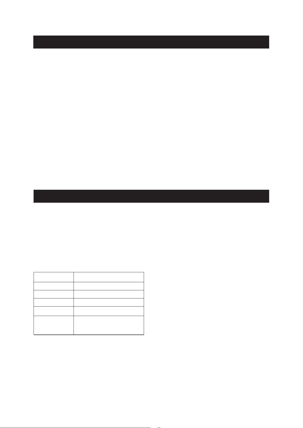
CARACTÉRISTIQUES TECHNIQUES
240V AC, 60Hz
8,14 lb (3,7 kg)
13,78 x 22,6 x 6,7 po
(35 x 57,5 x 17 cm)
Ce aéroconvecteur est conçu pour être monté de façon permanente au mur avec les
vis de support.
Ce aéroconvecteur est muni d'un circuit de protection thermique. Lors d'une surchauffe
de l'appareil, le courant est coupé. L'appareil se remet automatiquement en marche
après 10 minutes. Si le circuit de protection thermique est activé, déterminez la raison
de la surchauffe.
Modèle HIB-2000
Tension
Watts
Ampères
1,200/2,000 W
8,3 A
Poids net
Dimensions
(L x H x P)
RÈGLES DE SÉCURITÉ IMPORTANTES

16
INSTRUCTIONS D'INSTALLATION
Outils requis (non compris)
• Perceuse électrique
• Tournevis à tête cruciforme
• Ruban à mesurer
4. Insérez les 2 vis du haut également fournies en laissant un espace de 1/4 po (6
mm) entre la tête de la vis et le mur (Fig.5).
5. Accrochez le produit aux 2 vis que vous avez fixées en le tenant solidement entre
les mains.
MONTAGE AU MUR
1. L’appareil doit être installé au mur, en respectant une distance de 24 po (600 mm)
par rapport à la surface du plancher et 12 po (305 mm) des murs adjacents (Fig.2).
Aucune porte ne doit pouvoir se refermer sur l’appareil.
2. Faire 3 trous de diamètre légèrement inférieur aux chevilles en plastique incluses
dans l’emballage.
3. Insérez les chevilles. (Fig.3 & 4)
Fig.1
Fig.2
Minimum
12” (305mm)
Minimum
12” (305mm)
Minimum
24” (600mm)
Mur Mur
Plancher Fig.3 Fig.4
6” (153mm)
15 3/8” (319mm)
15 3/8” (319mm)
6” (153mm)
Fixez le porte-serviettes (Fig.1)
1. Placez deux extrémités du
porte-serviettes dans les fentes à
l'arrière de l'appareil et alignez les trous.
2. Vissez le porte-serviettes au convecteur
à l'aide des quatre vis fournies.
• L'installation doit être effectuée en conformité avec les exigences de la CEC par un
électricien qualifié seulement.
17
Fig.5
CÂBLAGE
INSTRUCTIONS D'INSTALLATION
Fig.8
• Effectuer les connections électriques à l'intérieur de la
boîte de jonction située à l'arrière de l'appareil (Fig.8).
• L'installation doit être effectuée selon les codes
électriques et de construction en vigueur dans votre
région.
• Il est nécessaire d'effectuer l'installation avec un câble
à deux fils de calibre 12 muni d'un fil de mise à la
terre.
• Cet aéroconvecteur doit être installé par un électricien qualifié et selon les codes local
et national du bâtiment.
• L'aéroconvecteur doit être utilisé avec une alimentation de CA 240 V et une mise à la
terre.
ATTENTION ! Avant de lâcher le produit vérifiez qu’il est bien accroché aux 2 vis.
6. Fixez enfin le produit avec la troisième vis en bas (Fig.6).
La figure 7 indique le mouvement de l’air généré par le aéroconvecteur. Ce corridor
doit rester dégagé afin de permettre une bonne circulation de l’air et assurer le bon
fonctionnement de l’appareil. Vous devez laisser au moins 12 po (305 mm) à l’avant de
l’appareil et 24 po (600 mm) à partir du plancher
Ne pas installer l’appareil sous une prise électrique.
Fig.6 Fig.7
Minimum
24” (600mm)
Minimum
12” (305mm)
Sortie d'air
Entrée d'air
18
FONCTIONNEMENT
CÂBLAGE
L'aéroconvecteur de salle de bains est muni de deux
boutons, un pour la minuterie de 60 minutes et un pour le
thermostat.
LE PRODUIT VOUS PERMET DE RÉGLER 2 MODES DE FONCTIONNEMENT :
RÉCHAUFFEMENT DE L’ENVIRONNEMENT ET MAINTIEN DE LA TEMPÉRATURE
En partant de la position marquée du symbole « », tournez la poignée du thermostat
dans le sens horaire jusqu'à entendre un « clic » : le produit commence alors à
fonctionner à 1200 W et le témoin lumineux s'allume.
Le thermostat maintient la température ambiante requise en allumant et éteignant
automatiquement le aéroconvecteur. Plus la poignée est tournée loin dans le sens
horaire, plus la température moyenne sera élevée. La position maximale du thermostat
correspond à environ 35°C, la minimale « » à environ 5°C.
Thermostat
Minuterie
Élément chauffant
Élément chauffant
800W
1 200W
Lumiére d'indicateur
Fusible Circuit de protcetion
thermiqne
moteur
L1
L2

19
FONCTIONNEMENT
Pour le réglage du thermostat :
Dans une pièce où la température dépasse les 35°C il est normal que le thermostat,
même si positionné au maximum, ne mette pas le convecteur en marche.
Dans une pièce où la température est trop basse (sous les 5°C) il est normal que le
thermostat maintienne l'appareil constamment en marche, même si positionné au
minimum.
Pour régler au mieux le thermostat nous conseillons cette procédure :
• Positionnez le thermostat au maximum et faire fonctionner l'appareil jusqu'à ce que la
température devienne confortable ;
• Ensuite tournez lentement la poignée du thermostat dans le sens anti-horaire jusqu'à
entendre un « clic » (l'appareil s'arrête) ;
• Tournez encore légèrement (seulement un peu) la poignée du thermostat dans le
sens horaire ;
• Dans cette position le thermostat maintient la température ambiante que vous avez
choisie.
RÉCHAUFFEMENT RAPIDE DE L'ENVIRONNEMENT
Après avoir réglé le thermostat ambiant selon la température ambiante requise,
tournez ensuite la poignée de la minuterie en sélectionnant le temps de
fonctionnement requis. Le produit fonctionne à 2000 W de puissance pour le temps
réglé, en produisant un réchauffement rapide de la pièce et ensuite en maintenant la
température ambiante réglée par le thermostat à une puissance de 1200 W.
SÉCURITÉ EN CAS DE FONCTIONNEMENT ANORMAL
En cas de surchauffe le système de protection de l'appareil désactive
automatiquement les éléments chauffants et le moteur, interrompant ainsi le
fonctionnement du convecteur de salle de bains. Dans ce cas le convecteur ne
fonctionne pas, mais l'indicateur lumineux sera allumé.
Dans un tel cas, effectuez les étapes suivantes:
• Arrêtez le convecteur et laissez-le refroidir pendant environ 15-20 minutes. Il est
impératif de placer le thermostat et la minuterie en position «OFF» pour pouvoir le
remettre en marche ;
• Vérifiez que le filtre anti-poussière n'est pas complètement obstrué et, le cas
échéant, nettoyez-le et remontez-le ;
• Surveillez d'éventuelles causes de surchauffe (par ex: obstacles devant la grille
d’entrée et/ou sortie de l'air, accumulation anormale de saleté, etc.) ;
• Allumez de nouveau le convecteur et vérifiez-en le bon fonctionnement. S'il ne
fonctionne pas, appelez le service à la clientèle au 1-866-967-7333.
Table of contents
Languages:
Other Ener-G+ Heater manuals

Ener-G+
Ener-G+ HEA-21538 User manual

Ener-G+
Ener-G+ HEA 21723 User manual

Ener-G+
Ener-G+ HEA-14756 User manual

Ener-G+
Ener-G+ HEA 21524 User manual

Ener-G+
Ener-G+ HEA 22000BHR User manual

Ener-G+
Ener-G+ HIW-750 User manual

Ener-G+
Ener-G+ HEA-21548-BB User manual

Ener-G+
Ener-G+ HEA 21523 User manual

Ener-G+
Ener-G+ HEA 21531 User manual


