ENERCON SUPER SEAL Series User manual

3/21/2018
INDUCTION CAP SEALER
SUPER SEAL™ SERIES
ML0071-601-06
OWNERS REFERENCE MANUAL
Enercon Industries Corp.
W140 N9572 Fountain Blvd.
P.O. Box 773 (53052-0773)
Menomonee Falls, WI 53051-0773, USA
Phone: (262) 255-6070
Fax: (262) 255-7784
Web Site: www.enerconind.com

TABLE OF CONTENTS
SECTION 1 – INTRODUCTION ...........................................................................................................................................................1
SAFETY AND WARNINGS...............................................................................................................................................1
SAFETY PRECAUTIONS .................................................................................................................................................2
UNDERSTANDING INDUCTION SEALING......................................................................................................................3
GENERAL.........................................................................................................................................................................3
MATERIAL VARIATIONS..................................................................................................................................................3
MULTIPLE LAYER LINERS (Figure 1)..............................................................................................................................3
SINGLE PIECE LINERS (Figure 2)...................................................................................................................................3
THE SEALING PROCESS.............................................................................................................................................3-4
UNPACKING AND INSPECTION .....................................................................................................................................4
DOCUMENTATION...........................................................................................................................................................4
OPTIONAL EQUIPMENT..................................................................................................................................................4
INDUCTION CAP SEALER FEATURES (Figure 3) ..........................................................................................................5
INFORMATION AND SAFETY LABELS (Figure 4)...........................................................................................................6
SECTION 2 – INSTALLATION..............................................................................................................................................................7
GENERAL.........................................................................................................................................................................7
SCREW ADJUSTABLE MOUNT OPERATION (Figures 5 & 6)........................................................................................7
FLOOR MOUNT INSTALLATION (Figure 7).....................................................................................................................7
POWER SUPPLY MOUNTING YOKE INSTALLATION (Figures 8 & 9) ...........................................................................8
MOUNT PLACEMENT AND INSTALLATION (Figures 10 & 11).......................................................................................8
ATTACHING POWER SUPPLY TO MOUNT (Figures 12 & 13) .......................................................................................9
MOBILE CART SYSTEM INSTALLATION (Figures 14 - 16)........................................................................................9-10
SYSTEM ALIGNMENT OVER CONTAINER...................................................................................................................10
THE SEALING HEAD AND SURROUNDING METAL ....................................................................................................10
CONTAINER PATH (Figure 17).................................................................................................................................10-11
SEALING HEAD CENTERING (Figure 18) .....................................................................................................................11
SETTING THE CONTAINER AND SEALING HEAD GAP (Figure 19)............................................................................11
DETAILED SEALING HEAD ALIGNMENT......................................................................................................................11
STANDARD FLAT SEALING HEAD (Figure 20).............................................................................................................11
STANDARD TUNNEL SEALING HEAD (Figure 21) ..................................................................................................11-12
DEEP TUNNEL SEALING HEAD (Figure 22) .................................................................................................................12
ALIGNMENT AND ADJUSTMENT "1" SEALING HEAD (Figure 23)...............................................................................12
SYSTEM REQUIREMENTS............................................................................................................................................12
TEMPERATURE.............................................................................................................................................................12
INPUT VOLTAGE REQUIREMENTS.........................................................................................................................12-13
GROUNDING REQUIREMENTS....................................................................................................................................13
BASIC UNIT - CABLE PROVISIONS (Figure 24)............................................................................................................13
INSTALLATION - CONTROL PROVISIONS...................................................................................................................13
EXTERNAL INTERLOCK................................................................................................................................................13
USING THE REMOTE START / INTERLOCK CABLE....................................................................................................13
USING THE DEFEAT CONNECTOR..............................................................................................................................13
STALLED BOTTLE DEFEAT CONNECTOR .............................................................................................................13-14
LOSS OF SEALING INDICATOR (LSI)...........................................................................................................................14
SECTION 3 – PRINCIPLES OF OPERATION.................................................................................................................................15
GENERAL.......................................................................................................................................................................15
CONTROL FUNCTIONS (Figure 25) .............................................................................................................................15
SEQUENCE OF OPERATION........................................................................................................................................16
LOCAL OPERATION (Figure 26)...................................................................................................................................16
SEALING WINDOW SETUP .....................................................................................................................................16-17
ADJUSTING THE LOSS OF SEAL INDICATOR ALARM SETPOINT .......................................................................17-19
REMOTE START OPERATION......................................................................................................................................19
AUTO CONTROL............................................................................................................................................................19
SECTION 4 – OPTIONAL EQUIPMENT...........................................................................................................................................20
GENERAL.......................................................................................................................................................................20
OPTIONS AVAILABLE....................................................................................................................................................20
MOBILE CART (Figure 27)..............................................................................................................................................20
STACK LIGHT (Figure 28) .........................................................................................................................................20-21
MOTION / FOIL DETECTION GROUP ...........................................................................................................................21
MOTION / FOIL DETECTION GROUP INTALLATION (Figure 29)................................................................................21
MOTION DETECTION ONLY (STALLED BOTTLE) ..................................................................................................21-22
STALLED BOTTLE SENSOR INSTALLATION (Figure 30).............................................................................................22
STALLED BOTTLE SENSOR SETTINGS AND ADJUSTMENTS (Figure 31)................................................................22
SENSITIVITY ADJUSTMENT .........................................................................................................................................22
DELAY OFF ....................................................................................................................................................................22

DELAY ON......................................................................................................................................................................22
SENSOR ADJUSTMENT PROCEDURE ...................................................................................................................22-23
FOIL LINER DETECTOR ONLY (Figure 32)...................................................................................................................23
FOIL LINER DETECTOR INSTALLATION (Figure 33) ...................................................................................................23
FOIL LINER DETECTOR CONTACTS CABLE (Figure 34) .......................................................................................23-24
FOIL LINER DETECTOR ALIGNMENT AND ADJUSTMENT (Figure 35) ......................................................................24
BEAM SENSOR LED OPERATION................................................................................................................................24
BEAM SENSOR SENSITIVITY ADJUSTMENT (Figure 36)............................................................................................24
BEAM AND PROXIMITY SENSOR LED OPERATION...................................................................................................24
PROXIMITY SENSOR SENSITIVITY ADJUSTMENT (Figure 37).............................................................................24-25
AUTO MODE (Figure 38)................................................................................................................................................25
EJECTOR SYSTEM........................................................................................................................................................25
EJECTOR INSTALLATION (Figure 39)......................................................................................................................25-26
SPARE PART KITS AVALABLE .....................................................................................................................................26
SECTION 4 – MAINTENANCE...........................................................................................................................................................27
GENERAL.......................................................................................................................................................................27
ROUTINE INSPECTION AND SERVICING....................................................................................................................27
VISUAL INSPECTION.....................................................................................................................................................27
EXTERNAL CONNECTIONS..........................................................................................................................................27
SEALING HEAD INSPECTION.......................................................................................................................................27
COOLING FANS AND BASE PLATE INSPECTION (Figure 40)................................................................................27-28
INTERNAL CONNECTIONS...........................................................................................................................................28
MAINTENANCE RECORD..............................................................................................................................................28
SECTION 5 – TROUBLESHOOTING................................................................................................................................................29
GENERAL.......................................................................................................................................................................29
REMOVE/INSTALL THE POWER SUPPLY COVER......................................................................................................29
FRONT PANEL 'F' INDICATIONS...................................................................................................................................29
F00 - OVER CURRENT TRIP....................................................................................................................................29-30
F02 AND TEMP - CAP TRIP OR OVER-TEMPERATURE (Figures 41 & 42)............................................................30-32
F03 - INTERLOCK FAULT.........................................................................................................................................32-33
F04 - UNDER VOLTAGE TRIP.......................................................................................................................................33
F05 - UNDER FREQUENCY TRIP.............................................................................................................................33-34
FRONT PANEL BLANK..............................................................................................................................................34-35
FAULT.............................................................................................................................................................................35
PUSHBUTTONS DO NOT FUNCTION......................................................................................................................35-36
OUTPUT STUCK AT MINIMUM......................................................................................................................................36
AUTO MODE AT MINIMUM............................................................................................................................................37
DISPLAY FLICKERS..................................................................................................................................................37-38
RUN NOT LIT OR BLINKING..........................................................................................................................................38
INVERTER OHM CHECK PROCEDURE........................................................................................................................39
BRIDGE RECTIFIER OHM CHECK PROCEDURE........................................................................................................39
APPLICATION TROUBLESHOOTING.......................................................................................................................40-43
SECTION 6 – PARTS LISTS...............................................................................................................................................................44
GENERAL.......................................................................................................................................................................44
HOW TO USE THIS PARTS LIST...................................................................................................................................44
HOW TO ORDER PARTS...............................................................................................................................................44
SHIPPING INSTRUCTIONS FOR RETURNS.................................................................................................................44
SCREW ADJUSTABLE FLOOR MOUNT PARTS BREAKDOWN (Figure 43)...............................................................45
MOUNTING BRACKET PARTS BREAKDOWN (Figure 44)...........................................................................................46
STANDARD POWER SUPPLY PARTS BREAKDOWN (Figure 45) ..............................................................................47
CE POWER SUPPLY PARTS BREAKDOWN (Figure 46).............................................................................................48
FAN AND SEALING HEAD MOUNTING PARTS BREAKDOWN (Figure 47)................................................................49
FRONT PANEL PARTS BREAKDOWN (Figure 48) ......................................................................................................50
OPTIONAL STALLED BOTTLE SENSOR PARTS BREAKDOWN (Figure 49)...............................................................51
OPTIONAL FOIL LINER DETECTOR PARTS BREAKDOWN (Figure 50) .....................................................................52
OPTIONAL STACK LIGHT PARTS BREAKDOWN (Figure 51)......................................................................................53
OPTIONAL MOBILE CART PARTS BREAKDOWN (Figure 52).....................................................................................54
SECTION 8 – MISCELLANEOUS......................................................................................................................................................55
MAINTENANCE RECORD.........................................................................................................................................55-56
PRODUCTION INFORMATION.................................................................................................................................57-58
NOTES.......................................................................................................................................................................59-60

ML0071-601-06 Super Seal™ Operations Manual Rev. A ENERCON INDUSTRIES
1
SECTION 1 – INTRODUCTION
WARNING!
Please read this manual carefully before installing, operating, or servicing.
DO NOT OPERATE THIS EQUIPMENT IN A HAZARDOUS ENVIRONMENT!
THIS EQUIPMENT PRODUCES A ELECTROMAGNETIC FIELD TO FACILITATE THE INDUCTION
SEALING PROCESS. THE ELECTROMAGNETIC FIELD QUICKLY HEATS ANY METAL WITHIN THE
FIELD AND MAY, UNDER CERTAIN CONDITIONS, IGNITE THE METAL OR SURROUNDING
MATERIALS. PERSONNEL SHOULD REFRAIN FROM PLACING JEWELRY, SUCH AS RINGS AND
WATCHES BENEATH OR WITHIN THE SEALING HEAD’S ELECTROMAGNETIC FIELD!
HIGH VOLTAGE is present within this equipment. As with any piece of ELECTRICAL equipment, one should
become familiar with the manual before applying power. Proper connections and operation are required for
safe use. FOLLOW INSTRUCTIONS for safety of personnel when operating or maintaining this equipment.
INSTALLATION of this equipment must be done in accordance with this manual, Enercon installation drawings
and local codes to ensure the safety of personnel in the area and in the building.
SAFETY AND WARNINGS
Before placing this equipment into operation, we
strongly recommend that you take the time to read
this manual carefully in its entirety to ensure you
understand all the safety and operational
requirements for using this equipment.
The heating capability of this equipment and the
presence of high voltage have the potential to cause
severe personal injury or property damage. To avoid
ignition of product liners from excessive heat, do not
exceed your established production output level, or
product dwell time, for a given application. Do not
operate this equipment if any of the wiring or
connections are exposed or damaged.
Before starting, operating, or making adjustments;
identify the components of the Induction Cap Sealer,
using this manual as a guide.
Personnel should use common sense and good
working practices while operating and maintaining
this equipment. All codes and operational guidelines
should be followed and the starting and stopping
sequence should be understood. Check all safety
devices and follow the procedures contained in this
manual.
Maintenance should only be performed by qualified
personnel, adequately equipped with the proper
tools. Follow the maintenance schedules as outlined
in the manual to ensure problem-free operation after
startup.
Safety instructions in this manual are called out in
colored safety boxes with bold-faced text for
emphasis. The signal words CAUTION,WARNING,
and DANGER are used to indicate hazard
seriousness levels as follows:
CAUTION!
CAUTION is used to indicate the presence of
a potentially hazardous situation which, if not
avoided may result in minor personal injury
or property damage.
WARNING!
WARNING is used to indicate a potentially
hazardous situation which, if not avoided, can
result in serious injury or death.
DANGER!
DANGER is used to indicate an imminently
hazardous situation which, if not avoided, will
result in serious injury or death.

ML0071-601-06 Super Seal™ Operations Manual Rev. A ENERCON INDUSTRIES
2
SAFETY PRECAUTIONS
DANGER!
The use of high voltage is necessarily employed in
the operation of this equipment. Precautions have
been taken in the design of this equipment to make it
as safe as possible for both operator and service
personnel. However, since no amount of interlocks
and safety devices can be absolutely infallible,
precautionary measures must always be taken when
working on this equipment.
Do not reach into the equipment or any electrical
enclosure without first removing the input voltage.
Never apply input voltage to the unit without the
cover on and securely in place.
Capacitors Store Charge: Never trust a capacitor
to be bled off completely. A meter or ground strap
should be used to check each stud or lead before
handling. Some capacitor studs, including those not
tied to bus work (not used), may build up a
considerable static charge. GROUND BEFORE
HANDLING!
Do not stand in water or on grounded surfaces or
touch grounded surfaces while reaching in any
system enclosure. A piece of wood or other
insulating material will act as an additional barrier to
stand on.
WARNING!
Do not operate this equipment in a hazardous
environment! The presence of High Voltage within
this equipment may result in explosion or fire when
operated near flammable vapors, fuels, or other
combustibles.
With the exception of your conveyor body, do not
permanently mount metal objects within the sealing
head’s electromagnetic field! These objects will be
heated as long as the electromagnetic field is on and
can create a burn hazard!
Do not attempt to seal products with damaged or
improperly applied liners, as they may overheat
causing the liner and container contents to ignite.
Do not Tamper With Safety Interlocks: The use of
safety interlocks is optional with your induction cap
sealing equipment. If safety interlocks are required
for your system, then under no circumstances should
any of these safety interlocks be defeated nor should
any of the interlocks be relied upon for removal of
voltage from the equipment.
Lockout / Tag Out: To ensure that the input voltage
cannot be applied to the equipment, remove the
input voltage and use the appropriate Lockout / Tag
Out procedures prior to removing any access covers,
panels, or entering the equipment in any manner.
ALWAYS use safety as the first step.
CAUTION!
Familiarize Yourself Thoroughly with the
Equipment.
Never attempt to work on this equipment unless you
are completely familiar with it.
Never assume that a circuit is dead, MAKE SURE!!!
Always Wear Appropriate Protective clothing and
Eyewear while working within the enclosure.
Do not connect any external control or monitoring
equipment, with the exception of appropriate test
equipment, to the internal circuits of this equipment.
Connecting external equipment in this manner may
cause failure of this equipment and create a potential
hazard to personnel.
The Sealing Head may be heavy! Always use
support blocks when removing the sealing head for
maintenance or troubleshooting.
CONTACT:
Enercon Customer Service Department
Phone Number: (262) 255-6070
Fax Number: (262) 255-2462
Website: www.enerconind.com
24hr Customer Service is available.

ML0071-601-06 Super Seal™ Operations Manual Rev. A ENERCON INDUSTRIES
3
UNDERSTANDING INDUCTION SEALING
General
Induction Sealing is a process used to seal
containers hermetically by using an electromagnetic
field to heat a heat-sealable foil liner located within a
closure. The Super Seal™ Induction Cap Sealer
converts a line voltage (240 VAC 1Ø or 3Ø / 50/60
Hz) to a high-frequency electromagnetic field in the
sealing head. This electromagnetic field heats your
liner by inducing currents into the metal of the foil
liner located within the closures of your containers.
High sealing speeds can be obtained using this
process making it well suited for both production
lines and laboratory applications.
Material Variations
Depending on the type of polymer used, an induction
seal can meet FDA requirements for “tamper
evident” packaging, or may simply provide leakage
protection and shelf life extension, often referred to
as a “freshness seal”. Many varieties of inner seal
polymers have been developed and are available
from a number of suppliers. Suppliers can assist you
in the selection of the proper liner for the multitude of
products and packaging methods used in the
packaging industry.
Multiple Layer Liners
A multiple layer liner (Figure 1) typically consists of a
pulp board layer (A), a wax layer (B), and a layer of
aluminum foil (C) coated with a polymer (D).
(A)(B) (C)(D)
(A)(B)
(C)(D)
BEFORE INDUCTION SEALING
AFTER INDUCTION SEALING
Figure 1
The polymer (D) must be compatible with your
container material and capable of producing the seal
strength and removal force required by your
application.
Single Piece Liners
A single piece foil liner (Figure 2) typically consists
of a layer of aluminum foil (A) coated with a polymer
(B) inside a closure.
BEFORE INDUCTION SEALING
AFTER INDUCTION SEALING
(A)(B)
(A)(B)
Figure 2
The polymer (B) must be compatible with your
container material and capable of producing the seal
strength and removal force required by your
application.
WARNING!
DO NOT attempt to induction seal damaged or
improperly applied liners as they may overheat
causing the liner and container contents to ignite.
The Sealing Process
When the closure is placed onto the container and
placed within the electromagnetic field produced by
the sealing head, several things occur.
1. An electrical current, called an eddy current, is
induced into the aluminum foil, resulting in a
resistance-type heating effect.

ML0071-601-06 Super Seal™ Operations Manual Rev. A ENERCON INDUSTRIES
4
2. The polymer coating melts and flows around the
lip of the container.
3. In Multiple Layer Liners the wax bond holding the
foil liner to the backing material is melted and the
wax is absorbed into the backing material.
When the electromagnetic field is shut off the
polymer cools and hardens, bonding the foil to the
container lip. When the closure is removed from the
container the metal foil will remain bonded to the lip
of the container and any backing materials (Multiple
layer liners only) will remain inside the closure.
NOTE:
A fundamental requirement for induction cap sealing
is to have the proper amount of torque on the cap,
which exerts a downward force when sealing.
Consult your cap supplier for the recommended
torque of your cap. A rule of thumb is to equate half
the liner’s millimeter size (diameter) to inch-pounds
of torque. For example, a 53mm liner would require
27 inch-pounds of torque. Also refer to the Torque
Requirement Table on Page 43 of this manual.
UNPACKING AND INSPECTION
IMPORTANT: The carrier accepted responsibility for
this shipment when the carrier signed the Bill of
Lading at the origin of shipment. If external damage
to the packaging was detected, it should have been
noted on the freight bill before signing it to
acknowledge receipt. If you give the carrier a clear
receipt for goods that have been damaged or lost in
transit, you do so at your own risk and expense. If
concealed loss or damage is discovered after
delivery, notify your carrier at once and request an
inspection. This is absolutely necessary for the
carrier to consider your claim. The carrier agent
should make an inspection and issue a loss or
damage report.
Your Super Seal™ Induction Cap Sealing System
may have been shipped in more than one container,
so compare the items received with the packing slip
to ensure all items that shipped were received. All
packages and crating should be carefully opened
and all items thoroughly inspected for damage.
NOTE:
Be extra careful if using a sharp instrument when
removing the protective wrapping from the
equipment. File a claim with the freight carrier for any
damage incurred during shipping. Enercon Industries
should also be contacted as soon as possible to
expedite the shipment of replacement parts.
CONTACT:
Enercon Customer Service Department
Phone Number: (262) 255-6070
Fax Number: (262) 255-2462
Website: www.enerconind.com
24hr Customer Service is available.
Enercon Parts Department
Phone Number: (262) 255-6070
Fax Number: (262) 255-2462
DOCUMENTATION
A system folder containing your printed System
Drawings, System and Safety Documentation, and
Miscellaneous Specification was provided with your
system. A CD-ROM was also provided with digital
copies of your system manuals, system drawings,
and the documents mentioned above.
OPTIONAL EQUIPMENT
Several options were available for purchase with
your Super Seal™ and the same care should be
used when opening these boxes. For installation and
setup of options included with your system refer to
SECTION 4 – OPTIONAL EQUIPMENT in this
manual.

ML0071-601-06 Super Seal™ Operations Manual Rev. A ENERCON INDUSTRIES
5
INDUCTION CAP SEALER FEATURES
Item # Description Item # Description
1 See Section 3 – Principles of Operation 4 Sealing Head
2 See Section 2 – Installation 5 Screw Adjustable Floor Mount
3 Rear of Power Supply
9.375"
(238mm)
15.5"
(394mm)
14.25"
(362mm)
65.5" (1664mm) Maximum Height
57.5 (1461mm) Minimum Height
23
CE
STANDARD
1
5
4
ON
I
O
OFF
SuperSeal
SuperSeal
REMOTE START /
INTERLOCKS
AUTO
CONTROL
STALLED
BOTTLE SENSOR FOIL DETECT
SENSORASSY
STACK
LIGHT
LSI
CONTACTS FOIL DETE CT
CONTACTS
REMOTE START /
INTERLOCKS
AUTO
CONTROL
STALLED
BOTTLE SENSOR FOIL DETECT
SENSORASSY
STACK
LIGHT
LSI
CONTACTS FOIL DETE CT
CONTACTS
Figure 3
Features Sealing Heads – Quick Change
1 Completely Air Cooled Part Number Type Of Head Cap Range
2 Electrical Rating:
208 or 240 VAC ± 10%, 50/60 Hz 1Ø SS50 – SS100 *
208 or 240 ± 10%, 50/60 Hz 3Ø SS100 3Ø (Non CE) *
LM4555-02
LM4555-102 “1” COIL 24 to 120mm
3 Stainless Steel Cabinet w/NEMA 4 rating. LM4033-32
LM4033 -132 WIDE FLAT 53 to 120mm
4 Screw Adjustable Floor Mount – Lockable.
5 Standard Control Features: LM4033-31
LM4033-131 WIDE TUNNEL 28 to 53mm
START/STOP
Output Adjustment / Digital Output % Meter LM4033-38
LM4033-138
LM4033-238
NARROW
TUNNEL 24 to 38mm
Built In Diagnostic Display
Remote Start Capabilities Consult Factory for Other Available Sealing Heads.
Capable of Interlocking with other equipment.
*See Rating Plate for Input Voltage Requirements. Failure to provide the input voltage shown on the system rating plate may cause system failure

ML0071-601-06 Super Seal™ Operations Manual Rev. A ENERCON INDUSTRIES
6
INFORMATION AND SAFETY LABELS
This page contains representative examples of the
typical placement of the labels that appear on your
Super Seal™ Induction Cap Sealing System. These
labels are designed to provide technical, functional,
and safety information required for operation of this
equipment. If for any reason a label is removed,
defaced, painted over or underlying parts are
replaced, we recommend you obtain a replacement
label from Enercon and re-apply them in the
locations shown.
STANDARD
CE
ON
I
O
OFF
REMOTE START /
INTERLOCKS
AUTO
CONTROL
STALLED
BOTTLE SENSOR FOIL DETECT
SENSOR ASSY
STACK
LIGHT
LSI
CONTACTS FOIL DETECT
CONTACTS
REMOTE START /
INTERLOCKS
AUTO
CONTROL
STALLED
BOTTLE SENSOR FOIL DETECT
SENSOR ASSY
STACK
LIGHT
LSI
CONTACTS FOIL DETECT
CONTACTS
SuperSeal
SuperSeal
Figure 4
FOIL alignment decals are only
required on Deep Tunnel Coils.
Located on both ends of
Sealing Head.
Located on both ends of
Sealing Head.
Decal will be located on
Both power supply connectors

ML0071-601-06 Super Seal™ Operations Manual Rev. A ENERCON INDUSTRIES
7
SECTION 2 – INSTALLATION
GENERAL
The basic Super Seal™ Induction Cap Sealing
Systems consist of a Power Supply, Sealing Head
(attached), Floor Mount, or optional Mobile Cart
Mounting System, and all required interconnection
cables. The system is designed to mount easily over
your conveyor using either the standard floor mount
or optional mobile cart, and this manual covers the
installation and setup of both types of mounting
systems. Your system may have been ordered with
some special, or optional, items that may have
requirements that deviate from standard. Therefore,
it is important to reference the system drawings and
paperwork to identify these items as well as to
understand any deviation from the standard
requirements listed in this manual.
SCREW ADJUSTABLE MOUNT OPERATION
The Screw Adjustable Mount is an assembly
designed to aid personnel in adjusting the power
supply height over the conveyor. With the sealing
head centered over the conveyor, the mount adjusts
to achieve the required gap between sealing head
and container by rotating the hand wheel either CCW
to raise, or CW to lower, the sealer over the
conveyor. Once the gap is set, a clamping system is
used to aid in maintaining the position of the mount.
A locking knob is used to loosen or tighten the
clamp. The locking knob rotates CCW to loosen,
allowing height to be adjusted, and CW to tighten
once the height is correctly set (Figure 5).
Lower
Raise
Locking
Knob Safety
Nut
DO NOT Remove the
Safety Nut unless
instructed
Figure 5
CAUTION!
Loosen the clamp before adjusting the mount
height.
Ensure that the safety nut located at the
bottom of the extrusion track is securely in
place.
All other visible screws on the mount, such as
the nylon tipped corner set screws, should not
be field adjusted as they are factory set.
The nuts used for mounting hardware and
accessories onto the screw adjustable mount may
slide within the extrusion track (Figure 6). If possible,
ensure the affected track is parallel to the floor when
removing bolts.
Figure 6
FLOOR MOUNT INSTALLATION
Once the floor mount has been unpacked the
conveyor mounting brackets will need to be
repositioned. Lay the mount on its side and remove
the lower bolt (1) and loosen the upper bolt (2) on
each bracket and rotate the bracket (3) into the
position shown. Reinstall the lower bolt (4) and
tighten the upper bolt (5). Repeat for the second
bracket (Figure 7).
12
45
3
Repeat For
Second Bracket
Figure 7

ML0071-601-06 Super Seal™ Operations Manual Rev. A ENERCON INDUSTRIES
8
POWER SUPPLY MOUNTING YOKE
INSTALLATION
Remove the 4 yoke mounting bolts from beneath the
power supply and slide the mounting bracket out
(Figure 8).
Figure 8
NOTE:
If the Optional Stack Light is included with your
system it should be installed at the same time as the
Power Supply Mounting Yoke.
When installing the yoke onto the mount, take into
account the dimensions of the power supply, sealing
head, and container when choosing its placement on
the mount. Ensure the yoke is at a height that will
allow your container to pass easily beneath the
sealing head. Place the optional stack light at the
highest point on the channel to allow the greatest
visibility. Remove the mounting bolts and affix the
yoke and stack light onto the mount (Figure 9).
Power Supply
Yoke Mounting Bolts
Stack Light
Mounting Bolts
Figure 9
MOUNT PLACEMENT AND INSTALLATION
Next find a suitable location along the conveyor that
allows sufficient space for installing the power supply
and any options that mount to the conveyor. Place
the mount against the conveyor and measure from
the center of your conveyor to the center of the floor
mounting brackets 11 ¼“ (Figure 10).
1114"
Recommended
distance
Conveyor Mounting
Brackets
Floor Mounting
Brackets
Figure 10
Drill holes in the conveyor and floor to secure the
mount, and bolt the mount in place (Figure 11).
Figure 11

ML0071-601-06 Super Seal™ Operations Manual Rev. A ENERCON INDUSTRIES
9
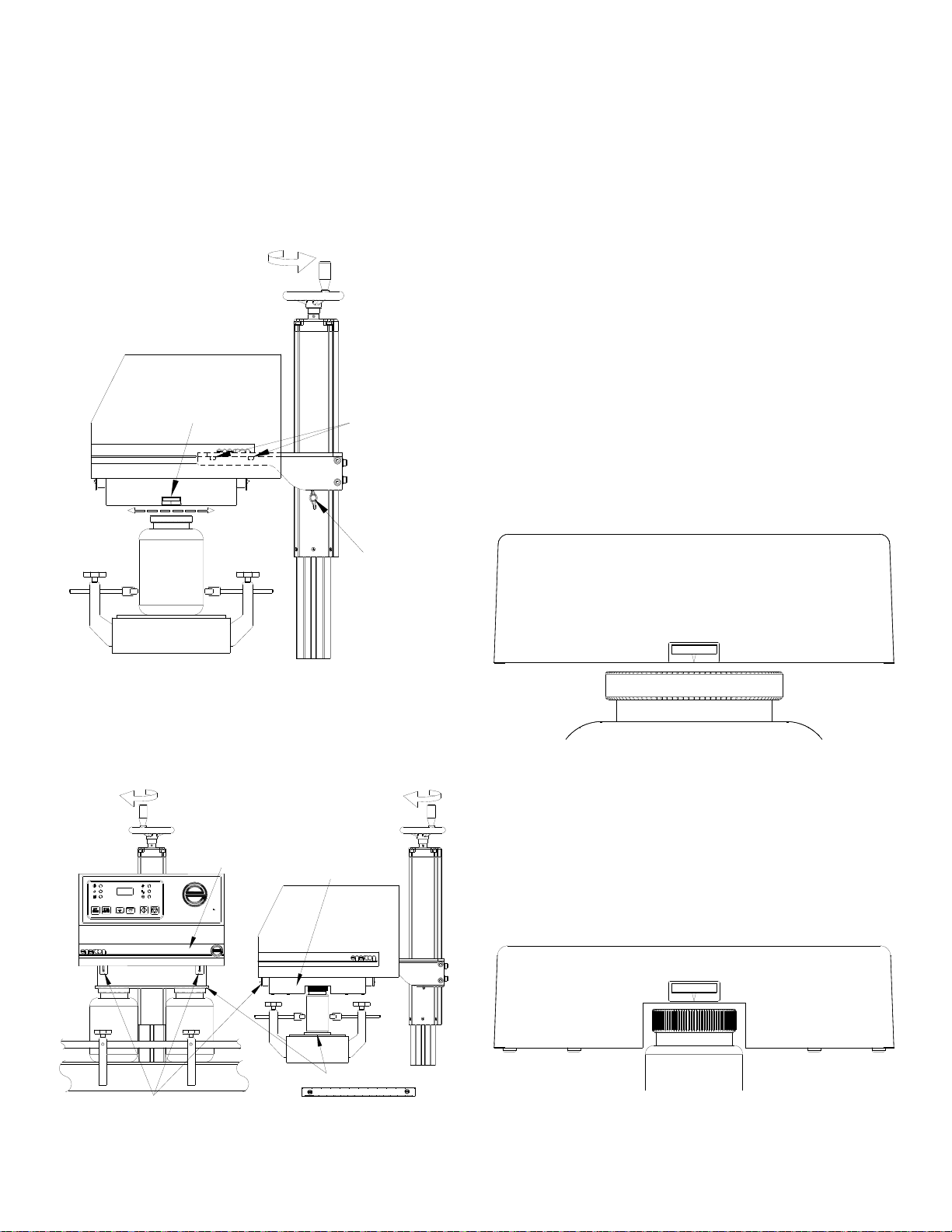
ATTACHING POWER SUPPLY TO MOUNT
It is recommended that the sealing head be removed
for ease of installation of the power supply. Remove
the 4 bolts from the 2 mounting brackets. The power
supply can be lifted up off of the sealing head by
raising the mount, or the head can be pulled straight
down from the power supply (Figure 12).
Figure 12
Install the power supply by lowering it onto the yoke
and aligning the Baseplate holes with the holes in
the yoke. Secure the power supply to the yoke using
the power supply mounting bolts removed earlier
(Figure 13). Once the power supply is secure,
reinstall the sealing head (Figure 12).
SuperSeal
SuperSeal
Figure 13
NOTE:
The sealing head should be reinstalled to the lowest
points in the slots on the mounting brackets to help
ensure the most consistent gap.
MOBILE CART SYSTEM INSTALLATION
When the cart system has been removed from its
crating, locate the leveling pads and remove them
from their packaging. Remove the protective yellow
sleeves and thread the pads into the mobile cart
base far enough that they do not contact the floor
(Figure 14).
LEVELING PADS
SuperSeal
SuperSeal
Figure 14
Next find a suitable location along the conveyor that
allows sufficient space for installing the cart and
power supply and any options that mount to the
conveyor. Unlock the casters and roll the system up
to the conveyor. Center the sealing head over the
conveyor, or product path, and lock all 4 casters.
Level the power supply to the conveyor by lowering
the leveling pads as required. Once set, tighten each
leveling pad’s lock nut (Figure 15).
Unlocked
Locked
SuperSeal
SuperSeal
Figure 15

ML0071-601-06 Super Seal™ Operations Manual Rev. A ENERCON INDUSTRIES
10
NOTE:
If the Optional Stack Light is included with your
system it will have been factory installed.
Depending upon the combined height of your
conveyor and container, it may be necessary to
adjust the rough height of the power supply. Due to
the weight, the power supply will need to be securely
supported before loosening the yoke mounting bolts.
Once the power supply is securely supported, adjust
the height by raising or lowering the mount within the
yoke’s channel. Once the adjustment has been
made ensure all hardware is retightened (Figure 16).
Lower
Raise
Locking
Knob
Safety
Nut
DO NOT Remove the
Safety Nut unless
instructed
Yoke
Mounting
Bolts
SuperSeal
SuperSeal
Figure 16
CAUTION!
Loosen the clamp before adjusting the mount
height.
Ensure that the safety nut located at the
bottom of the extrusion track is securely in
place.
All other visible screws on the mount, such as
the nylon tipped corner set screws, should not
be field adjusted as they are factory set.
SYSTEM ALIGNMENT OVER CONVEYOR
It is important that each end of the sealing head be
equal in height and alignment in relation to the
conveyor. This will be critical for ensuring the
containers are entering and exiting at the same gap
and centering on the sealing head. The better the
liner is positioned within the sealing head’s
electromagnetic field, the more efficiently the liner
will be heated as it passes.
WARNING!
.
The sealing head produces a electromagnetic
field that quickly heats any metal within the
field.
With the exception of the metal frame of your
conveyor, DO NOT mount any metal objects
within 6” (15cm) of the sealing head.
The Sealing Head and Surrounding Metal
Due to the nature of induction heating, the sealing
head will induct into all metal objects that are
mounted within range of its electromagnetic field.
The electromagnetic field weakens as it moves away
from the sealing head until it dissipates at a distance
of approximately 6” (15cm) at the farthest. Even at its
weakest point the electromagnetic field will
inductively heat metal objects, though the rate of
heating will be slower.
Smaller metal objects, such as screws or brackets,
which are mounted within the sealing head’s
electromagnetic field will be continually heated
whenever the electromagnetic field is active. This
scenario has the potential to create a severe burn
hazard and should be eliminated if possible.
Larger metal objects, such as your conveyor’s metal
frame, which are located within the electromagnetic
field, tend not to show signs of heating due to the
mass of these objects. The only adverse affect
typically associated with large metal objects is a
slight change in the performance of the sealer, which
in most cases is not noticeable due to the
insignificance of the change. This scenario is
considered normal in most production atmospheres
and is safe to both operators and the equipment.
Container Path
The container path beneath the sealing head must
be as consistent as possible, and this can be
achieved with the use of guide rails. If guide rails are
used, ensure that the metal rails beneath the sealing
head are removed, or at least 6 inches (15cm) below
the sealing head (Figure 17).
Guide Rails
Figure 17
ML0071-601-06 Super Seal™ Operations Manual Rev. A ENERCON INDUSTRIES
11
Sealing Head Centering
Raise the system height, if needed, by loosening the
locking knob and rotating the hand wheel counter-
clockwise, and then retighten the locking knob.
Loosen the power supply mounting bolts on each
side to allow free movement of the power supply
over the container. Align both the input and exit side
centerline labels to the center of the container’s cap.
Retighten the mounting bolts (Figure 18).
CENTERLINE
Locking
Knob
Power Supply
Mounting Bolts
Centerline
Label
Raise
Figure 18
Setting the Container and Sealing Head Gap
Use the 1/8 inch (3mm) thick gap gauge provided by
Enercon to set the gap between the container and
sealing head (Figure 19).
Sealing Head Mounting Brackets
STOPSTART
AUTO
FAULT
TEMP
OUTPUT (%)
RUN
REMOTE
READY
Gap Gauge
Tunnel Sealing
Head
Flat Sealing
Head
Lower
Lower
Super Seal
Super Seal
Figure 19
As shown, the gap gauge placement will depend
upon the type of sealing head supplied with the
system. Once the gap gauge is in place, loosen the
locking knob and lower the system by rotating the
hand wheel clockwise until the bottom of the flat
head or the top of the tunnel touches the gauge or
cap. Ensure the gap is equal on both ends of the
sealing head. Retighten the locking knob and
remove the gap gauge.
DETAILED SEALING HEAD ALIGNMENT
To ensure repeatability of your sealing process,
proper alignment of the sealing head is critical. Use
the following steps to help achieve proper alignment.
Standard Flat Sealing Head
The standard Flat Sealing Head is typically used on
larger containers between 53mm and 120mm. The
sealing head must be centered over the cap with a
1/8” (3mm) air gap between the bottom of the sealing
head and the top of the cap (Figure 20).The 1/8”
(3mm) gap will allow the highest line speeds with the
most consistent seal results.
CENTER LINE
Figure 20
Standard Tunnel Sealing Head
The Standard Tunnel Sealing Head is typically used
on containers 53mm and smaller. The sealing head
must be centered over the cap with a 1/8” (3mm) air
gap between the top of the sealing heads tunnel and
the top of the cap (See Figure 21).The 1/8” (3mm)
gap will allow the highest line speeds with the most
consistent seal results.
CENTER LINE
Figure 21

ML0071-601-06 Super Seal™ Operations Manual Rev. A ENERCON INDUSTRIES
12
Deep Tunnel Sealing Head
The Deep Tunnel Head is typically used on special
applications where the cap or container will not allow
the product to fit within the standard tunnel head.
Deep tunnel head have a centerline indicator at the
top of the tunnel and foil indicators on both sides of
the tunnel. In these applications, the center
alignment should be set with the cap in place but the
sealing head height should be set with the cap
removed. Align the foil indicators to the lip of the
container where the foil liner rests. If cap or container
dimensions prevent the lip of the container from
reaching the centering marks then position the
container lip into the tunnel as far as possible
(Figure 22).
CENTER LINE
FOIL
FOIL
LINER &
CONTAINER LIP
Cap & Liner must be
aligned with all 3
labels.
Figure 22
Alignment And Adjustment “1” Sealing Head
In many instances, multiple cap sizes will be run on
the same power supply. The “1” Sealing Head and
Pivot Kit allows for moving the sealing head to
accommodate various size caps without having to
exchange the sealing head. The “1” sealing head
can be pivoted in approximately seven (7) degree
increments to four different positions (Figure 23).
100 - 120
63 - 89
20 - 38
43 - 58
CAP
(mm) CAP
(mm)
63 - 89
100 - 120
43 - 58
20 - 38
4
4
3
2
1
3
2
1
Figure 23
The table that follows indicates the desired pivot
position for the listed liner sizes. The pivot assembly
brackets serve to guide the sealing head rotation,
providing the proper pivot angle for the liner sizes you
are sealing. The knurled locking knobs serve to lock the
sealing head in place.
NOTE:
No tools are required to change the position of the
sealing head. Loosen both of the knurled locking knobs,
one at each end of the sealing head. Rotate the sealing
head to the proper position for the cap size in use.
Center the proper indicator line on the locking knobs at
each end of the sealing head and hand tighten the
locking knobs.
Item # Description
1 20 – 38mm Position
2 43 – 58mm Position
3 63 – 89mm Position
4 100 – 120mm Position
Proper alignment of the “1” Sealing Head is critical, use
the following steps for proper set up.
1. First align the power supply and sealing head over
the conveyor with the sealing head in the #1
position. The mount / cart must be secure.
2. Align and gap the product to the sealing head using
the same criteria used for a Flat Sealing Head (See
Figure 20) ensuring that it runs centered along the
entire length of the sealing head.
3. Choose the proper position for the caps size to be
run and pivot the sealing head to that position, Refer
to table above.
NOTE:
Check alignment whenever the pivot angle is to be
changed to ensure proper sealing.
SYSTEM REQUIREMENTS
Temperature
The Super Seal™ has been designed to operate in
an ambient air temperature range of 32º-104º F (0º-
40º C) @ 80% relative humidity, non-condensing.
Input Voltage Requirements
The Super Seal™ requires a specific input voltage to
function properly. The required input voltage is listed
on the rating plate on the side of the power supply
(See Figure 4 on Page 6), and in the drawing list
provided with your system. The standard voltages
required are 208 or 240 VAC ± 10%, 1Ø / 3Ø, 50/60
hertz.
WARNING!
The power supply should not be operated
without the grounded line cord connected to a
grounded receptacle.
DO NOT bypass the ground terminal.
Grounding Requirements
All system components must be connected to a good
earthen ground point using the green ground wire

ML0071-601-06 Super Seal™ Operations Manual Rev. A ENERCON INDUSTRIES
13
provided in the power cord. Local codes will dictate
the means of terminating the ground wire. A fused
disconnect switch must be located between the input
voltage source and the power supply.
BASIC SYSTEM
Each Super Seal™ is supplied with 2 standard cables
and 2 defeat connectors. The two cables provided are
the Remote Start / Interlocks Cable (1) and the Alarm
Connector Cable (2). The 2 defeat connectors are for
the REMOTE START / INTERLOCKS circuit (1) and
STALLED BOTTLE SENSOR circuit (3). Both the
cables and defeat connectors will connect to the rear
panel of the power supply (Figure 24).
INTERLOCK DEFEAT CONNECTOR
(USED WHEN NEITHER INTERLOCKS NOR
REMOTE START ARE REQUIRED)
TO CUSTOMER
N.O. INTERLOCK
CONTACT
TO CUSTOMER
N.O. REMOTE
START CONTACT
BLACK
RED
WHITE
GREEN
BLACK
RED
WHITE
FOR CUSTOMER LOSS OF
SEALING INDICATOR (LSI) ALARM,
USE AS REQUIRED
1
2
REMOTE START /
INTERLOCKS
AUTO
CONTROL
STALLED
BOTTLE SENSOR FOIL DETECT
SENSOR ASSY
STACK
LIGHT
LSI
CONTACTS FOIL DETECT
CONTACTS
1
2
33
STALLED BOTTLE DEFEAT CONNECTOR
(REQUIRED WHEN NEITHER OF THE THE MOTION
OPTIONS ARE INCLUDED WITH YOUR SYSTEM)
Figure 24
BASIC INTERCONNECTIONS
Using The Remote Start / Interlocks Cable
A cable is provided to extend the wiring of the
Remote Start / Interlock cable to external contacts as
shown in Figure 24. Connect the Remote Start /
Interlock cable securely to the rear panel of the
power supply and run the open end of the cable to
your N.O. dry contacts. Ensure you use the Black
and Red wires for the Interlock function and the
White and Green wires for the Remote Start function.
The Remote Start function is tied to the
LOCAL/REMOTE pushbutton located on the front
panel of the unit.
External Interlock
The Super Seal™ comes standard with provisions
for interlocking the control circuits. The two interlock
wires must be connected to a normally open contact
that closes when the interlock is met for the unit to
start. This “closed circuit” may be accomplished in a
number of different ways but is absolutely necessary
for the unit to start and run. Do not apply any voltage
across these wires.
WARNING!
Applying voltage to the interlock control
circuits may result in a failure of circuit
components.
DO NOT APPLY VOLTAGE ACROSS THE
INTERLOCKS!
Remote Start
The Super Seal™ comes standard with provisions
for starting and stopping the power supply remotely.
The two remote start wires must be connected to a
normally open contact and the contact must be
closed to start the power supply and open to stop it
(Refer to REMOTE START OPERATION on Page
19). Do not apply any voltage across these wires.
USING THE DEFEAT CONNECTORS
Remote Start / Interlocks
A defeat connector is included to provide the
required closed circuit for the interlocks when the
interlock and remote start functions are not used.
This simply requires connecting the defeat connector
to the REMOTE START / INTERLOCKS connector
on the rear panel of the power supply. The jumper
wire inside the defeat connector allows the unit to
start without providing an external closed contact.
Stalled Bottle Sensor
A second defeat connector is included to provide the
required closed circuit for the Stalled Bottle Sensor
circuit when none of the Motion options is included
with your system. This simply requires connecting
the defeat connector to the STALLED BOTTLE
SENSOR connector on the rear panel of the power
supply. The jumper wire inside the defeat connector
allows the unit to start without having the optional
stalled bottle sensor connected to the power supply.
Refer to SECTION 4 – OPTIONS for further details
on the Motion Options that are available.
NOTE:
Even if you are not using either of the defeat
connectors, ensure you do not discard either of
them. Keep them in a safe place, as they may be
required to substitute for the Remote Start /
Interlocks cable or the Stalled Bottle Sensor,if
they are damaged, or for troubleshooting these
circuits.

ML0071-601-06 Super Seal™ Operations Manual Rev. A ENERCON INDUSTRIES
14
LOSS OF SEALING INDICATOR ALARM (LSI)
The Loss of Sealing Indicator Alarm provides you
with a set of dry contacts that will allow you to drive
an external alarm, or monitor the power supply’s
output status using a monitoring circuit of your
choice.
The alarm circuit is programmable from the power
supply front panel, giving you the ability to quickly
and easily customize the alarm setpoint for a wide
variety of products.
As shown in Figure 24 on Page 13, a contact cable
is provided to extend the alarm contacts to your
alarm or monitoring circuit. The alarm contacts
consist of a Common (COM), Normally Open (N.O.)
and a Normally Closed (N.C.) contact. The contact
cable connects to the LSI CONTACTS connector on
the rear panel of the power supply and the open end
of the contact cable can be run to your external
alarm or monitoring circuit.
Typically the N.C contact will be used for triggering
your alarm circuit, as this is the non-powered state of
the relay contacts. The relay will only change state
when the power supply is running and the output
percentage is greater than the programmed trip
setpoint; see ADJUSTING THE LOSS OF SEAL
INDICATOR ALARM SETPOINT on Pages 17-18.
When using the alarm contacts to an alarm circuit,
ensure the supplied voltage does not exceed the
contacts rating of 24 VDC, 2 Amps.
DANGER!
The contact cable is provided to extend the dry
contacts of the alarm circuit only.
All necessary precautions should be taken
when wiring the contact cable to powered
external circuitry.
When the contact cable is connected to
external powered circuits, proper lockout / tag
out procedures should be observed for the
external circuits.
This must be done before disconnecting the
connector cable from the power supply to
prevent the cable from being energized when
disconnected.

ML0071-601-06 Super Seal™ Operations Manual Rev. A ENERCON INDUSTRIES
15
SECTION 3 – PRINCIPLES OF OPERATION
GENERAL
Before operating this equipment, we
recommend reading this section in its entirety to
ensure you understand all the safety and operational
requirements for using this equipment. Also, please
refer to SECTION 1 – INTRODUCTION, Pages 1
and 2, to become familiar with all safety
requirements and precautions.
WARNING!
DO NOT operate this equipment in a hazardous
environment.
Operating this equipment near flammable vapors,
fuels, or combustibles; including atmospheric
product dust or particulates, may result in
explosion or fire, causing serious injury or death.
CONTROL FUNCTIONS
The power supply utilizes a Digital Output Meter to
represent its output level as a percent of available
output, colored LED’s to represent control and fault
status, and pushbuttons to control the power
supply’s output and operational modes (Figure 25).
Figure 25
Front Panel Indicators
The power supply front panel includes the following
indicators to represent its control and fault status.
Control Display Lamps
Green; breaker/switch energized
- input voltage applied.
Green; output current applied to
the sealing head, and regulated.
Amber; Remote Start Mode
Selected.
Amber; AUTO Mode Selected.
Fault Display Lamps
Red; Temperature Fault.
Red; Power Supply Failure.
Digital Output Meter
The Output Meter displays power supply’s
output in percentage of available output. The Output
Meter will flash the selected output level setpoint
when the circuit breaker or disconnect switch is
placed in the ON position. Once the START
command is applied, the number displayed on the
Output Meter will stop flashing. This is the actual
output level of the power supply.
Front Panel Push Pushbuttons
START Starts Power Supply locally.
STOP Stops Power Supply locally, Resets
Faults.
UP For adjusting output level up.
DOWN For adjusting output level down (Limited
at minimum setting).
LOCAL/
REMOTE For selecting either LOCAL or REMOTE
Start Mode.
AUTO/
MANUAL For selecting either AUTO or MANUAL
power control Mode.
WARNING!
The sealing head produces an electromagnetic
field that quickly heats any metal within the field.
DO NOT pass metal objects, other than
appropriate liner materials, beneath the sealing
head.
Personnel should keep jewelry, such as rings
and watches, from placement beneath or within
the sealing head’s electromagnetic field.
WARNING!
Never allow the liners to reach a temperature
sufficient to ignite the liner or container contents.
Ensure the dwell time beneath the sealing head is
correct and DO NOT allow containers to stop
within the electromagnetic field.
Failure to observe these requirements may lead
to fire or explosion.
WARNING!
DO NOT attempt to induction seal damaged or
improperly applied liners as they may overheat
causing the liner and container contents to
ignite.

ML0071-601-06 Super Seal™ Operations Manual Rev. A ENERCON INDUSTRIES
16
SEQUENCE OF OPERATION
LOCAL OPERATION
A Circuit Breaker or Disconnect Switch is
provided on the rear panel of the power supply for
applying the input voltage to the power supply
(Figure 26).
Disconnect Switch
ONI
O
OFF
Circuit Breaker
Figure 26
Placing the circuit breaker or disconnect switch into
the ON position will apply the input voltage, and all of
the LEDs on the front panel will initially be lit and the
output meter will flash 888. After the initial startup, all
of the LEDs except the READY LED will go out, and
the output meter will revert to flashing the last
selected output level setpoint. If the power supply
was in either the REMOTE or AUTO modes when
the input voltage was last removed, the
corresponding LED will also be lit.
If either of the fault LEDs is lit, press the STOP
pushbutton to reset the fault. If the fault will not reset,
refer to SECTION 5 – TROUBLESHOOTING.
If either the REMOTE or AUTO LEDs are lit, press
the LOCAL/REMOTE pushbutton to allow
LOCAL start control, and/or the AUTO/MANUAL
pushbutton to allow MANUAL power control.
With the power supply in LOCAL and MANUAL
modes with no faults indicated, use the UP /
DOWN arrows to increase or decrease the
output level until the desired output level setpoint is
displayed. Press the START pushbutton to start
the power supply.
Once the power supply is running, the RUN
LED will be lit and the Output Meter will
stop blinking and display the actual output level as a
solid number .
NOTE:
The Output Level can be adjusted while the output
meter is blinking and when the power supply is
running.
Press the STOP pushbutton to stop the power
supply. When the STOP pushbutton is pressed, only
the READY lamp should be lit and the number on
the output meter will again be flashing the output
level setpoint.
Ensure you always STOP the power supply prior to
placing the circuit breaker or disconnect switch into
the OFF position. This will remove the input voltage
from the power supply and all of the LEDs and the
output meter will go out. Failure to STOP the power
supply may result in damage to the power supply
components.
NOTE:
If the RUN LED is not lit when the
power supply is running, output meter is not flashing,
the Loss of Seal Indicator Alarm setpoint is above
the output level you are running at. (Refer to
ADJUSTING THE LOSS OF SEAL INDICATOR
ALARM SETPOINT on Pages 17-18).
SEALING WINDOW SETUP
In the induction sealing process there are several
variables that make almost every application unique.
Keep in mind that rarely is one set up solution right
for every application. Most applications will have
their own unique variables for the perfect seal and
each variance must be given consideration when
determining the output level for a given application.
WARNING!
Never allow the liners to reach a temperature
sufficient to ignite the liner or container contents.
Ensure the dwell time beneath the sealing head is
correct and DO NOT allow containers to stop
within the electromagnetic field.
Failure to observe these requirements may lead
to fire or explosion.
WARNING!
DO NOT attempt to induction seal damaged or
improperly applied liners as they may overheat
causing the liner and container contents to
ignite.
NOTE:
An application consists of the package (container,
liner, cap), product (type, temperature, fill level),
dwell time (length of time the liner is in the inductive
field), sealing head alignment (gap, centering, level)
and the induction sealer (inductive field strength
and frequency) being used. For more detailed
application information, refer to “APPLICATION

ML0071-601-06 Super Seal™ Operations Manual Rev. A ENERCON INDUSTRIES
17
TROUBLESHOOTING” in SECTION 6 –
TROUBLESHOOTING.
Once the system is running it is recommended that
you attempt to determine the sealing window of the
products that will be sealed by this power supply.
This test will require several containers, caps, and
liners and should be performed at the line speed
each product will be run at during actual production.
NOTE:
The initial output level chosen for this test can be a
level determined by the testing results of your
product samples by Enercon, or an output level of
your own choosing. If no samples were sent for
testing, it is recommended that the initial output level
be 50% or lower. For the following examples, we will
be using 50% as the initial output level.
With the circuit breaker or disconnect switch ON,
press the UP /DOWN arrows until the
desired output level setpoint is reached. Press the
START pushbutton and ensure the unit starts
and is running at the output level you selected.
Run a single container under the sealing head at
your production line speed. Once through the sealer,
wait at least 30 seconds for the liner to cool and then
remove the cap and inspect the liner condition.
NOTE:
Do not perform this test on a container that has been
previously run, as this can give inaccurate test
results. A new container, liner, and cap should be
used each time the test requires a container to be
run.
No Seal
If no seal was achieved, raise the output in 5%
increments and continue running a single container
until the liner begins to adhere. Continue the test,
raising the output by 1% or 2%, until the liner seals
around the entire lip of the container. This is the
lower limit of the sealing window. Continue the test,
raising the output by 1%, until the liner shows signs
of overheating then lower the output by 1% and this
is the upper limit of the sealing window. Choose the
output level, within this window, that gives the
desired strength and peelability as your production
output level.
Burned Liner
If the initial test results in a burned liner, lower the
output in 5% increments and continue running a
single container until the burning subsides. Continue
the test, lowering the output by 1% or 2%, until the
liner shows no signs of overheating. This is the
upper limit of the sealing window. Continue the test,
lowering the output by 1%, until the liner no longer
seals the entire lip of the container. Raise the output
by 1% and this is the lower limit of the sealing
window. Choose the output level, within this window,
that gives the desired strength and peelability as
your production output level.
Good Seal
If a good seal was achieved, note the output level,
then lower the output 1% and continue running a
single container until the liner no longer seals the
entire lip of the container. Raise the output by 1%
and this is the lower limit of the sealing window.
Reset the output to the level noted after the initial
test. Continue the test raising the output by 1% until
the liner shows signs of overheating. Lower the
output by 1% and this is the upper limit of the sealing
window. Choose the output level, within this window,
that gives the desired strength and peelability as
your production output level.
Production Test
When the sealing window and production output %
have been determined, a production test should be
run. Set up a group of containers that is at least
twice the length of the sealing head. The grouping
should be back to back to simulate a worst case
scenario. Press the START pushbutton and
verify the unit is running at your production output
level determined in the previous steps. Run the
containers at your production line speed and then
verify that all containers sealed properly.
If not all of the containers sealed, double check the
results of the sealing window setup and refer to
“APPLICATION TROUBLESHOOTING” in
SECTION 6 – TROUBLESHOOTING of this manual.
If all of the containers sealed properly, then the
system is ready to be put into production.
ADJUSTING THE LOSS OF SEAL INDICATOR
ALARM SETPOINT
The Loss of Sealing Indicator Alarm (LSI) is
programmable to allow setting the power supply’s
lower output limit, or threshold, for the alarm circuit
operation. If, for any reason, the output displayed on
the output meter falls below this programmed alarm
setpoint the alarm relay contacts will change state.
Refer to LOSS OF SEALING INDICATOR ALARM
(LSI) on Page 14 for more information.
The default alarm setpoint is 60%, and is set during
the testing phase of the power supply. You will be
able to adjust the alarm setpoint to any level through
the full output range of your power supply.
Table of contents
Other ENERCON Food Saver manuals


