ENERCON SUPER SEAL 300 User manual

6/7/2023
SUPER SEAL™ 300 / 400 / 600
INDUCTION CAP SEALER
ML0185-001-01
OWNER’S REFERENCE MANUAL
DANGER: Read entire Owner’s Reference Manual
before installing, operating, or maintaining equipment.
Mailing Address:
Enercon Industries Corp.
P.O. Box 773
Menomonee Falls, WI 53052-0773
Shipping Address:
Enercon Industries Corp.
W140 N9572 Fountain Blvd.
Menomonee Falls, WI 53051
(262) 255-6070 - www.enerconind.com

Table of Contents
SECTION 1 – SAFETY AND WARNINGS ................................................................................................................................................. 1
1.1 GENERAL SAFETY INFORMATION ............................................................................................................................ 1
1.2 SAFETY PRECAUTIONS .............................................................................................................................................. 1
1.3 EQUIPMENT SAFETY LABELS .................................................................................................................................... 2
1.4 EQUIPMENT INFORMATION LABELS ......................................................................................................................... 3
SECTION 2 – INSTALLATION ................................................................................................................................................................... 4
2.1 GENERAL ..................................................................................................................................................................... 4
2.2 UNPACKING AND INSPECTION .................................................................................................................................. 5
2.3 CONTACT INFORMATION ........................................................................................................................................... 5
2.4 SYSTEM REQUIREMENTS .......................................................................................................................................... 5
2.41 Input Voltage Requirements .................................................................................................................................. 5
2.42 Grounding Requirements ...................................................................................................................................... 6
2.43 Temperature Rating .............................................................................................................................................. 6
2.5 INSTALLATION GUIDELINES ...................................................................................................................................... 6
2.51 Power Supply Enclosure Specs ............................................................................................................................ 6
2.6 FLOOR MOUNT INSTALLATION .................................................................................................................................. 6
2.61 Floor Mount Assembly .......................................................................................................................................... 6
2.62 Floor Mount Installation ......................................................................................................................................... 6
2.63 Power Supply Installation ...................................................................................................................................... 7
2.7 OPTIONAL MOBILE CART INSTALLATION ................................................................................................................. 7
2.8 SYSTEM ALIGNMENT .................................................................................................................................................. 8
2.81 Container Path and Standard Sealing Head Alignment ........................................................................................ 8
2.82 Deep Tunnel Sealing Head Setup ....................................................................................................................... 10
2.83 All-In-One Universal Sealing Head Setup ........................................................................................................... 10
2.9 CABLE CONNECTIONS ............................................................................................................................................. 10
2.10 INPUT VOLTAGE ...................................................................................................................................................... 10
SECTION 3 – PRINCIPLES OF OPERATION ......................................................................................................................................... 11
3.1 GENERAL ................................................................................................................................................................... 11
3.2 OPERATING INSTRUCTIONS .................................................................................................................................... 11
3.21 APPLYING THE INPUT VOLTAGE .................................................................................................................... 11
3.22 Power Supply Front Panel .................................................................................................................................. 12
3.3 BASIC OPERATION .................................................................................................................................................... 12
3.31 Local Operation ................................................................................................................................................... 12
3.32 Power Supply Output Range Verification ............................................................................................................ 13
3.4 POWER SUPPLY SETUP ........................................................................................................................................... 13
3.41 Start/Stop Setup .................................................................................................................................................. 13
3.42 Level Setup ......................................................................................................................................................... 13
3.43 Alarm Setup ........................................................................................................................................................ 13
3.5 OPERATING WINDOW SETUP .................................................................................................................................. 13
3.51 Minimum and Maximum Power Levels................................................................................................................ 13
3.52 Production Power Level ...................................................................................................................................... 14
3.6 REMOTE OPERATIONS ............................................................................................................................................. 14
3.61 Remote Start/Stop .............................................................................................................................................. 14
3.62 Remote Level Control ......................................................................................................................................... 14
SECTION 4 – EQUIPMENT INTERCONNECTION & OPERATION WITH OPTIONS ............................................................................. 15
4.1 GENERAL ................................................................................................................................................................... 15
4.2 MOBILE CARTS .......................................................................................................................................................... 15
4.3 AUTOMATION I/O CABLE .......................................................................................................................................... 15
4.31 External Interlock ................................................................................................................................................ 15
4.32 Loss of Seal Alarm .............................................................................................................................................. 16
4.33 Ready.................................................................................................................................................................. 16
4.4 STACK LIGHT ............................................................................................................................................................. 16
4.41 Installation ........................................................................................................................................................... 16
4.42 Setup................................................................................................................................................................... 17
4.43 Operation ............................................................................................................................................................ 17
4.5 STALLED BOTTLE DETECTION ................................................................................................................................ 17
4.51 Installation and Alignment ................................................................................................................................... 17
4.52 Setup................................................................................................................................................................... 17
4.521 Direction...................................................................................................................................................... 18
4.522 Stalled Bottle Time ...................................................................................................................................... 18
4.53 Operation ............................................................................................................................................................ 18
4.6 FOIL DETECTION ....................................................................................................................................................... 18
4.61 Installation and Alignment ................................................................................................................................... 18
4.62 Optional Cap Inspection Output Cable Wiring ..................................................................................................... 19
4.63 Setup................................................................................................................................................................... 19

4.631 Proximity Sensor Setup .............................................................................................................................. 19
4.632 Beam Sensor Setup .................................................................................................................................... 20
4.633 Optional Cap Inspection Output Cable Setup ............................................................................................. 20
4.64 Operation ............................................................................................................................................................ 20
4.7 BOTTLE BACKUP ....................................................................................................................................................... 20
4.71 Installation and Alignment ................................................................................................................................... 20
4.72 Setup................................................................................................................................................................... 21
4.73 Operation ............................................................................................................................................................ 21
4.8 EJECTOR .................................................................................................................................................................... 21
4.81 Installation ........................................................................................................................................................... 21
4.82 Setup................................................................................................................................................................... 22
4.821 Air Pressure Setup ...................................................................................................................................... 22
4.822 Eject Delay.................................................................................................................................................. 22
4.823 Eject Time ................................................................................................................................................... 22
4.83 Operation ............................................................................................................................................................ 22
4.9 SPARE PART KITS ..................................................................................................................................................... 23
SECTION 5 – MAINTENANCE ................................................................................................................................................................ 24
5.1 GENERAL ................................................................................................................................................................... 24
5.2 PREVENTIVE MAINTENANCE ................................................................................................................................... 24
5.3 WEEKLY CHECKS ...................................................................................................................................................... 24
5.31 Visual Inspection ................................................................................................................................................. 24
5.32 External Connections .......................................................................................................................................... 24
5.4 MONTHLY CHECKS ................................................................................................................................................... 24
5.41 Sealing Head Inspection ..................................................................................................................................... 24
5.42 Cooling Fans Inspection...................................................................................................................................... 25
5.43 Internal Connections ........................................................................................................................................... 25
5.5 MAINTENANCE RECORD .......................................................................................................................................... 25
SECTION 6 – TROUBLESHOOTING ...................................................................................................................................................... 26
6.1 GENERAL ................................................................................................................................................................... 26
6.2 FRONT PANEL ISSUES ............................................................................................................................................. 26
6.21 Blank Front Panel ............................................................................................................................................... 26
6.22 Buttons Do Not Function ..................................................................................................................................... 27
6.3 DISPLAYED FAULTS .................................................................................................................................................. 27
6.341 Removing/Installing Output Capacitors ............................................................................................................. 28
6.4 FACTORY RESET ...................................................................................................................................................... 30
6.5 INVERTER AND BRIDGE RECTIFIER ....................................................................................................................... 30
6.51 Inverter Ohm Check Procedure .......................................................................................................................... 30
6.52 Bridge Rectifier Ohm Check Procedure .............................................................................................................. 31
6.53 Replacing Inverters and Bridge Rectifiers ........................................................................................................... 31
6.6 FACTORY ASSISTANCE ............................................................................................................................................ 31
SECTION 7 – MISCELLANEOUS ............................................................................................................................................................ 32
MAINTENANCE RECORD ................................................................................................................................................ 32
PRODUCTION INFORMATION ........................................................................................................................................ 34
NOTES .............................................................................................................................................................................. 36

1
ML0185-001-01 Super Seal™ 300 / 400 / 600 Induction Cap Sealer Owner’s Reference Manual Rev. H Enercon Industries
SECTION 1 – SAFETY AND WARNINGS
DANGER!
DO NOT OPERATE THIS EQUIPMENT IN AN EXPLOSIVE ENVIRONMENT!
1.1 GENERAL SAFETY INFORMATION
DANGER: Before placing this equipment into operation, you must read this manual carefully, in its entirety, to
ensure you understand all the safety and operational requirements for using this equipment.
This equipment produces an Electromagnetic Field to facilitate the induction sealing process. The
Electromagnetic Field quickly Heats any metal within the field and may, under certain conditions, Ignite
the metal or surrounding materials. Personnel should refrain from placing jewelry, such as rings and watches
beneath or within the sealing head’s electromagnetic field!
HIGH VOLTAGE is present within this equipment. As with any piece of ELECTRICAL equipment, one should
become familiar with the manual before applying power. Proper connections and operation are required for
safe use. FOLLOW INSTRUCTIONS for safety of personnel when operating or maintaining this equipment.
INSTALLATION of this equipment must be done in accordance with this manual, Enercon installation
drawings and local codes to ensure the safety of personnel in the area and in the building.
Safety instructions in this manual are called out in colored safety boxes with bold-faced text for emphasis.
The signal words CAUTION, WARNING, and DANGER are used to indicate hazard levels to personnel, and
NOTICE is used to indicate potential hazards to property.
DANGER
WARNING
DANGER: Indicates an imminently hazardous
situation which, if not avoided, will result in
death or serious injury.
WARNING: Indicates a potentially hazardous
situation which, if not avoided, could result in
death or serious injury.
CAUTION
NOTICE
CAUTION: Indicates a potentially hazardous
situation which, if not avoided, may result in
minor or moderate injury.
NOTICE: Indicates a potentially hazardous
situation which, if not avoided, could result in
damage to property.
1.2 SAFETY PRECAUTIONS
DANGER
Do not operate this equipment in an explosive environment, or in the presence of flammable materials! Operation
near flammable vapors, fuels, combustibles; including atmospheric product dust or particulates will result in
explosion or fire.
Before installing, wiring, starting, operating, or making any adjustments, identify the components of the
induction cap sealer using this manual as a guide.
The use of High Voltage is necessarily employed in the operation of this equipment. Precautions have been
taken in the design of this equipment to make it as safe as possible for both operator and service personnel.
However, since no amount of interlocks and safety devices can be absolutely infallible, precautionary
measures must always be taken when working on this equipment.
Do not reach into the equipment, or any electrical enclosure, without first removing the input voltage.
Do not apply voltage to the system without all covers on and securely in place.
Lockout / Tag Out: To insure that voltage cannot be applied to the equipment while work is performed, secure
or disconnect voltage supplies using the appropriate Lockout / Tag Out procedures. Ensure Lockout / Tag Out is
complete prior to entering the equipment in any manner. ALWAYS use safety as the first step!

2
ML0185-001-01 Super Seal™ 300 / 400 / 600 Induction Cap Sealer Owner’s Reference Manual Rev. H Enercon Industries
Capacitors Store Charge: Never trust a capacitor to be bled off completely. A meter or ground strap should
be used to check each stud or lead before handling. Some capacitor studs, including those not tied to bus
work (not used), may build up a considerable static charge. GROUND BEFORE HANDLING!
Never assume that a circuit is dead, MAKE SURE!!!
Do not stand in water or on grounded surfaces or touch grounded surfaces while reaching in any system
enclosure. A piece of wood or other insulating material will act as an additional barrier to stand on.
WARNING
Do not tamper with Safety Interlocks: Under no circumstance should any of your system’s safety interlocks
be defeated, nor should any safety device be relied upon for removal of voltage from the equipment.
Test and Verify: Test all system safety interlocks to ensure they are fully functional before placing equipment
into production after maintenance, troubleshooting, or an extended shutdown. If an induction sealer is
integrated into an automated or partially automated system (e.g., integrated into a conveyance system) all
safety features and interlocks present in the entire system should be tested and checked at regular intervals
and after maintenance, troubleshooting, or an extended shutdown.
SEALING CONTAINERS OF FLAMMABLE OR COMBUSTIBLE MATERIAL:If an induction cap sealer will
be used to seal containers of flammable or combustible materials, it must be integrated into a conveyance
system, designed, and installed by a qualified professional integrator/installer with knowledge of the entire
conveyance system and product to be sealed. Such conveyance system must include all appropriate
safety features, including a stalled bottle detector and/or a bottle back-up sensor to detect
conveyance system failures. In the event of a conveyance system failure, containers remaining under
an induction cap sealer may overheat, causing damage to the container and product, and pose a
potential fire risk.
IMPORTANT – stalled bottle detectors and/or bottle back-up sensors are not substitutes for specific safety
features integrated into the entire conveyance system (e.g., manual emergency stops or other system safety
interlocks) and proper training on their use. Under no circumstance should operators be allowed to or required to
directly contact containers containing flammable or combustible material during the sealing process.
CAUTION
The equipment should only be installed, tested, operated and maintained by personnel familiar with the handling
and hazards of high voltage and electrostatic discharge, and are familiar with the instructions and safety
precautions contained within this manual.
Personnel should use common sense and good working practices while operating and maintaining this
equipment. Follow all codes and understand the starting and stopping sequence.
Familiarize yourself thoroughly with the equipment, and Never attempt to work on this equipment unless you
are completely familiar with it.
Always wear appropriate protective clothing and eyewear while working within the enclosure.
Only qualified personnel, equipped with the proper tools and protective gear, and following appropriate
safeguards, should perform system maintenance.
NOTICE
Follow the maintenance schedules as outlined in the manual to ensure problem free operation after startup.
Do not connect any 3rd party control or monitoring equipment, except for appropriate test equipment, to the
internal circuits of this equipment.
Connecting 3rd party equipment in this manner may result in failure of this equipment.
1.3 EQUIPMENT SAFETY LABELS
Safety labels alert personnel to potential hazardous situations. If for any reason a safety label is removed
or defaced, you must obtain a replacement label from Enercon.
Safety labels are located on system components where direct contact, or contact beyond a point, would
expose personnel to death or serious injury.
3
ML0185-001-01 Super Seal™ 300 / 400 / 600 Induction Cap Sealer Owner’s Reference Manual Rev. H Enercon Industries
NA0056 – Located on the Sealing Head Connectors.
NA0136 – Located on the back of the power supply.
NA0137-01 – Located on the Sealing Head.
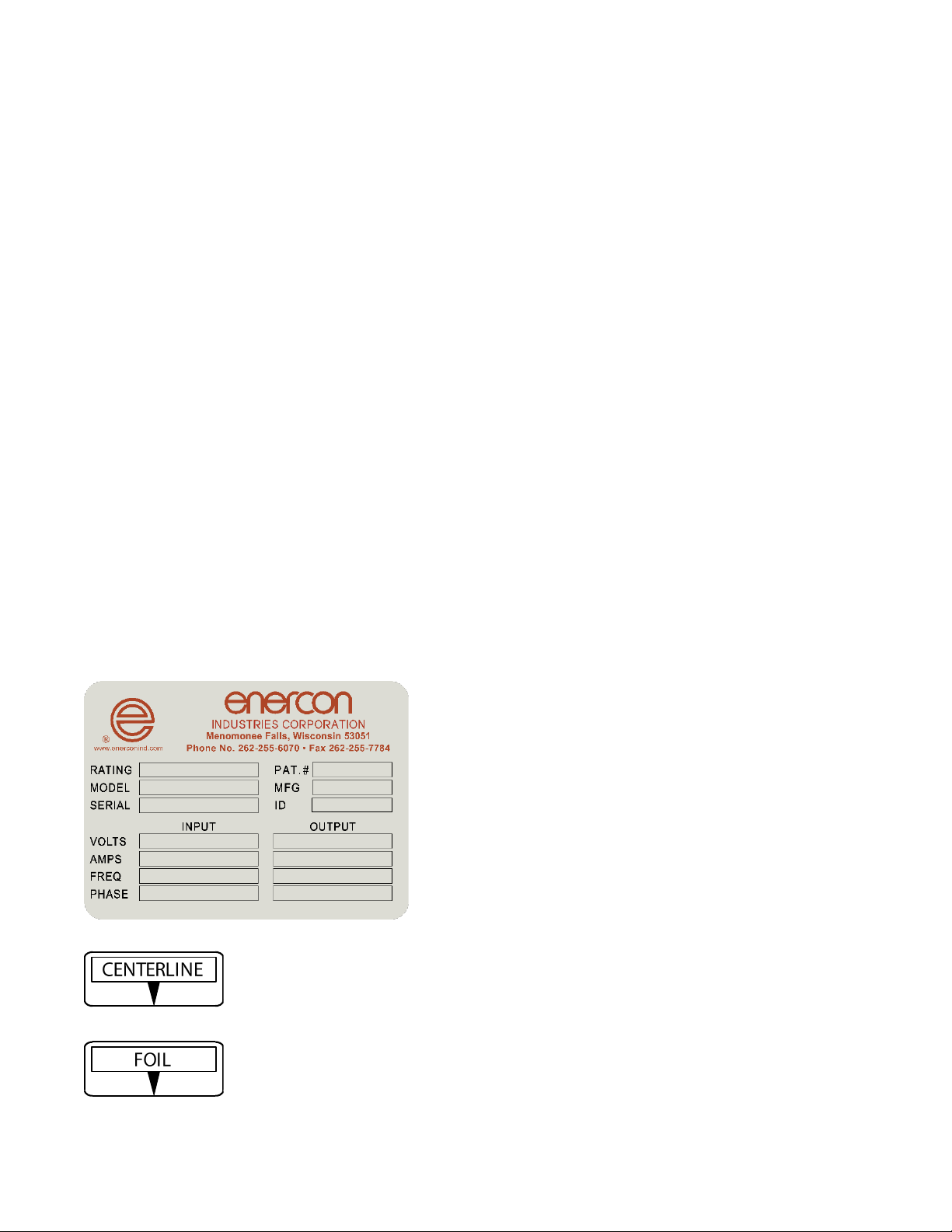
1.4 EQUIPMENT INFORMATION LABELS
Information labels provide information on equipment requirements that if not followed could result in damage
to the equipment. If for any reason an information label is removed or defaced, you should obtain a
replacement label from Enercon.
Rating Plate – Located on the side of the power supply.
NA0023 – Located on both ends of all Sealing Heads.
NA0181 – Located on the sides of each end of the Deep Tunnel Sealing Head openings.

4
ML0185-001-01 Super Seal™ 300 / 400 / 600 Induction Cap Sealer Owner’s Reference Manual Rev. H Enercon Industries
SECTION 2 – INSTALLATION
2.1 GENERAL
DANGER: Before installing this equipment, please read this section completely, and refer to the safety warnings
of Section 1, to become familiar with all the safety requirements and precautions for this equipment.
All applicable safety requirements and precautions including those contained in this manual must be followed
for safe and efficient operation of an induction cap sealer.
Induction cap sealers should be installed and operated in accordance with all applicable Federal, state and
local laws and regulations.
Induction cap sealers (and all ancillary equipment) should be specified, integrated, and installed by qualified
professionals. Proper specification, integration, and installation should include a risk assessment of the entire
conveyance system (if used in conjunction with an induction cap sealer) in accordance with applicable
industry standards. This risk assessment can only be conducted by the owner or its contracted conveyance
system integrator/installer with knowledge of and access to the conveyance system equipment and product
to be sealed.
An induction cap sealer should be properly configured for the intended sealing operation, including proper
alignment and elevation with respect to a conveyance system (if used) and proper sealing window for the
application. Induction cap sealer configuration should be re-checked and adjusted following any changes to
the sealing operation (e.g., different container or product) and/or to the conveyance system in which an
induction cap sealer is used. As a reminder, Enercon offers a Start-Up Assistance program to help its
customers properly configure an induction cap sealer. Please contact Enercon regarding any
conveyance line or product changes.
All operators of an induction cap sealer should receive proper training regarding operation of an induction
cap sealer and the product being sealed. Training should include instruction on the specific safety features
integrated into the entire conveyance system (e.g., emergency stop operation and location(s)). Enercon
recommends that operators of an induction cap sealer be required to read and follow the most recent
applicable operating manual provided with the induction cap sealer and/or available from Enercon. Enercon
is also available to provide training and information to operators as part of its Start-Up Assistance program.
All equipment used on a conveyance system should be maintained in accordance with manufacturer
recommendations. As a reminder, Enercon recommends routine Preventative Maintenance visits,
which includes Enercon’s standard safety evaluation.
WARNING: SEALING CONTAINERS OF FLAMMABLE OR COMBUSTIBLE MATERIAL. If an induction
cap sealer will be used to seal containers of flammable or combustible materials, it must be integrated into a
conveyance system, designed and installed by a qualified professional integrator/installer with knowledge of
the entire conveyance system and product to be sealed. Such conveyance system must include all
appropriate safety features, including a stalled bottle detector and/or a bottle back-up sensor to
detect conveyance system failures. In the event of a conveyance system failure, containers remaining
under an induction cap sealer may overheat, causing damage to the container and product, and pose
a potential fire risk.
IMPORTANT - stalled bottle detectors and/or bottle back-up sensors are not substitutes for specific safety
features integrated into the entire conveyance system (e.g., manual emergency stops or other system safety
interlocks) and proper training on their use.
WARNING: Under no circumstance should operators be allowed to or required to directly contact containers
containing flammable or combustible material during the sealing process.
DANGER
The potential of electrical shock is present if all system
components are not properly grounded.
The power supply should not be operated without either
a 3-prong or 3-wire grounded line cord connected to a
grounded receptacle.
Do not by-pass the ground terminal.
High voltage is present within the cabinet, only qualified
personnel should be allowed to work within the
equipment.
Buss capacitors discharge very slowly, disconnect
power and verify they are discharged before working on
the power supply.
5
ML0185-001-01 Super Seal™ 300 / 400 / 600 Induction Cap Sealer Owner’s Reference Manual Rev. H Enercon Industries
WARNING
Magnetic Field heats metal within the field.
Keep jewelry away from the sealing head.
Do not use damaged or improperly applied liners.
Liners may overheat causing liner and container
contents to ignite.
This equipment should not be used to seal containers
containing flammable or combustible contents unless
integrated into a conveyance system with proper
safety equipment including a stalled bottle detector
and/or bottle back-up sensor.
CAUTION
Small metal objects, such as screws, guiderails and
brackets, located within the electromagnetic field, will
continually heat creating a burn hazard.
NOTICE
Do not apply voltage across the interlocks!
Applying voltage to the interlock control circuits
may result in a failure of the control board
interlock circuit components.
Loosen the locking knob before adjusting the standard
mount height.
Ensure the standard mount safety nut remains securely
in place.
All other visible mount screws are factory set and
cannot be field adjusted.
2.2 UNPACKING AND INSPECTION
The carrier accepted responsibility for your shipment when they signed the Bill of Lading at the point of origin of
the shipment.
Your system may have shipped in more than one package. Compare the packing slip with the items received to
ensure that all items were delivered.
Inspect contents of each package for concealed loss or damage. If loss or damage is discovered after delivery,
notify the carrier at once to request an inspection. The carrier’s agent must perform an inspection and issue a
loss or damage report. This is absolutely necessary for the carrier to consider your claim.
If issues are found, contact Enercon Industries as soon as possible to expedite the shipment of replacement parts.
2.3 CONTACT INFORMATION
Enercon Customer Service Department 24hr
Customer Service Phone Number: (262) 255-6070
Service e-mail Address: service@enerconmail.com
Parts e-mail Address: parts@enerconmail.com
Website: www.enerconind.com
2.4 SYSTEM REQUIREMENTS
2.41 Input Voltage Requirements
The required input voltage is listed on the rating plate on the side of the power supply and in the
drawings provided with your system.
SS300
200 - 240VAC, 1Ø, 5 Amps, 50/60 Hz ± 10%
SS400
200 - 240VAC, 1Ø, 7.5 Amps, 50/60 Hz ± 10%
SS600
200 - 240VAC, 1Ø, 10 Amps, 50/60 Hz ± 10%
6
ML0185-001-01 Super Seal™ 300 / 400 / 600 Induction Cap Sealer Owner’s Reference Manual Rev. H Enercon Industries
2.42 Grounding Requirements
All system components must be connected to a good earthen ground point using the green ground wire
provided in the power cord. Local codes will dictate the means of terminating the ground wire. A fused
disconnect switch must be located between the power source and the power supply.
2.43 Temperature Rating
The Super Seal™ is designed to operate in an ambient temperature range of 41º - 104F (5º - 40C) @
80% maximum relative humidity, non-condensing.
2.5 INSTALLATION GUIDELINES
For safe and proper operation, use this manual, your system drawings, and any other supplied documents
when installing system components.
2.51 Power Supply Enclosure Specs
Stainless Steel, IP55 Rated
Dimensions
Height*
Width
Depth
11 – 11/16” (297mm)
18 – 11/32” (466mm)
16 – 1/2” (419mm)
*Power Supply height is measured from the top of the cover to bottom of the output CT without a sealing head attached.
2.6 FLOOR MOUNT INSTALLATION
The basic Super Seal™ Induction Cap Sealing System consists of a Power Supply, Sealing Head and Adjustable
Floor Mount. The Floor Mount is designed for easy adjustment of the system height over your conveyor.
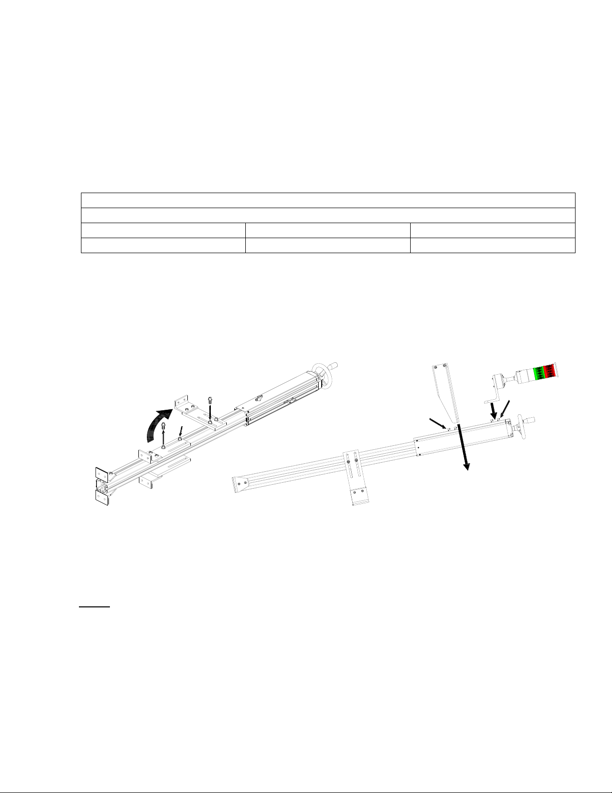
2.61 Floor Mount Assembly
Lay the mount on its side to reposition the conveyor brackets. Remove the lower bolt [1] and loosen the upper
bolt [2], rotate the bracket [3] and reinstall [4] the lower bolt. Rotate the mount and repeat for the second
bracket and align the brackets (Figure 1).
Figure 1
Reposition the mount to install the power supply yoke [5]. Remove the bolts [6], place the yoke [7] over
the nuts and reinstall the mounting bolts. Slide the yoke high enough to allow the system to clear your
conveyor and tighten the yoke to the mount.
If the optional stack light [8] is supplied, remove the bolts [9], place the bracket [10] over the nuts and
reinstall the bolts. Slide the stack light to the highest point and tighten the bolts.
NOTE:
If a nut moves out of position, realign it with the bracket hole using a screwdriver or similar tool.
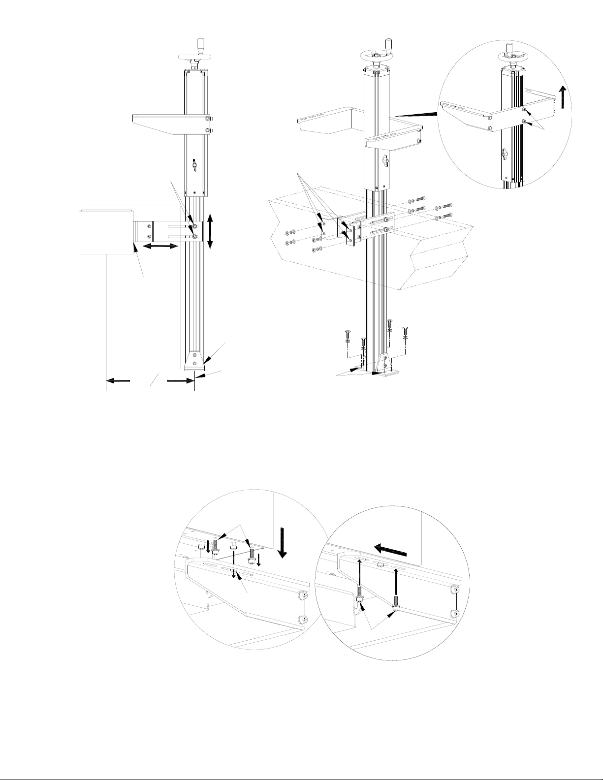
2.62 Floor Mount Installation
Choose a location with sufficient room for the power supply and options. Measure 12 ½” from the center
of the conveyor [1] and mark that point on your floor [2] (See Figure 2).
Place the mount against the conveyor [3] and adjust [4] the brackets to center them on your conveyor, and
to center the floor brackets [5] on the 12 ½” mark [2]. Ensure the mount is square [6] to your conveyor and
tighten the conveyor bracket bolts [7].
Mark the conveyor [8] and floor [9] mount hole locations, remove the mount and drill the holes. Install
appropriately sized anchors in the floor and realign the mount with the holes and bolt the mount securely
to the conveyor [10] and floor [11].
12
4
3
6
7
8
9
5
10
7
ML0185-001-01 Super Seal™ 300 / 400 / 600 Induction Cap Sealer Owner’s Reference Manual Rev. H Enercon Industries
Figure 2
If the mounting yoke placement will not allow power supply to clear the conveyor, raise the yoke height
using the hand wheel [12], or by loosening the yoke mounting bolts [13] and raise the mounting yoke [14].
2.63 Power Supply Installation
Remove the power supply’s mounting bolts [1] and lift the power supply over the mounting yoke [2].
Align the guide bolts [3] with the keyholes [4], and lower [5] the power supply into position. Slide the
power supply forward [6] and reinstall the mounting bolts [1] (Figure 3).
Figure 3
2.7 OPTIONAL MOBILE CART INSTALLATION
When your system includes an optional Standard [1] or Deluxe [2] Mobile Cart, the power supply is shipped
mounted to the cart (See Figure 4).
Remove the leveling pads [3] from the cart base and install them so they clear the ground [4].
12 12"
3
2
6
10
8
10
4
5
9
11
11
4
1
7
13
14
12
42
3
5
1
2
1
6

8
ML0185-001-01 Super Seal™ 300 / 400 / 600 Induction Cap Sealer Owner’s Reference Manual Rev. H Enercon Industries
Figure 4
Choose a location with a sufficient footprint to accommodate the cart base, power supply, and options and
ensure the bottom of the sealing head [5] will clear the conveyor.
To raise the sealing head, loosen the locking knob [6] on the standard cart mount, not required on deluxe
cart, and rotate [7] the handle counterclockwise to raise the sealing head.
Unlock [8] the casters and roll the cart under the conveyor [9]. Center the sealing head over the conveyor,
lock [10] the casters once the cart is in position and lower the leveling pads [11] to contact the ground to
prevent accidental movement while continuing setup.
NOTE:
If the optional Stack Light is included with your system, it is factory installed to the cart.
2.8 SYSTEM ALIGNMENT
During the induction sealing process, the liner position must be uniform through the electromagnetic field to allow
repeatable sealing results. This is achieved with a consistent gap and path beneath the sealing head.
CAUTION: Due to the nature of an electromagnetic field, it will induct into metal located within the field,
heating it to varying degrees.
Small metal objects: such as screws, guiderails, and brackets, that experience continual heating may become
burn hazards and must be removed from the field or located at least 6 inches (15cm) below the sealing head.
Large metal objects, such as your conveyor, tend not to heat due to their mass, but may cause a slight change
in performance of the sealer. This is typically unnoticeable, and is considered normal, and safe, to both personnel
and equipment.
2.81 Container Path and Standard Sealing Head Alignment
The container path and air gap must be consistent along the full length of the sealing head.
Ensure the power supply is high enough to place your container beneath the sealing head [1] and center
your container on the conveyor [2] using guide rails [3] or other guidance system (See Figure 5).
Ensure both ends of the sealing head are centered over the container [4]. If needed, loosen the power
supply mounting bolts [5] and slide [6] the power supply over the container [6], and retighten the bolts.
If the sealing head is not aligned with the conveyor, refer to Figure 2 or 4, and adjust the alignment of
the mount or cart to correct the power supply alignment to the conveyor.
3
LEVELING PADS
2
110
8
6
4
44
99
11 11
55
77
11 11

9
ML0185-001-01 Super Seal™ 300 / 400 / 600 Induction Cap Sealer Owner’s Reference Manual Rev. H Enercon Industries
Figure 5
To set the air gap, place a container at each end of the sealing head, with the supplied 3mm (1/8”) gap
gauge [1] between the containers and sealing head. Place the gauge between the container and
conveyor on a tunnel sealing head [2], or between the sealing head and your container on a flat sealing
head [3] (Figure 6).
Figure 6
Lower the power supply until it contacts the container cap [4] or gap gauge [5], by loosening the locking knob
[6] on the standard mount and optional standard mobile cart mount [A] and adjusting the hand wheel [7]. With
an optional deluxe mobile cart [B] you only need to adjust the handle [8] to lower the power supply.
Once the air gap is properly set, tighten the locking knob [6], if required, and remove the gap gauge.
51
33
Induction Sealer
6
2
33
4
5
Induction Sealer
6
1
1
2
4
Induction Sealer
1
7
8
A
B
3
26
54
10
ML0185-001-01 Super Seal™ 300 / 400 / 600 Induction Cap Sealer Owner’s Reference Manual Rev. H Enercon Industries
2.82 Deep Tunnel Sealing Head Setup
Deep tunnel sealing heads are a specialty sealing head and are typically used in applications where
the cap or container won’t allow the product to fit within the standard tunnel sealing head. Deep tunnel
sealing heads have a standard centerline indicator [1] and two foil indicators [2] on each end of the
sealing head (Figure 7).
Figure 7
The initial setup of the deep tunnel sealing head is the same as a standard tunnel sealing head (Refer to
Figure 5). After the initial setup, ensure the cap is removed from your container and lower the sealing head
to align the foil indicators with the lip of the container [3] where the foil liner rests.
If cap or container dimensions prevent the lip of the container from reaching the foil indicators, position the
container lip into the tunnel as far as possible, ensuring the container can still pass without contacting the
sealing head.
2.83 All-In-One Universal Sealing Head Setup
The All-In-One Universal Sealing Head is designed to run a variety of applications, typically 24mm to
120mm, by allowing adjustment of the coil’s position within the housing. The adjustments do not require
tools, allowing single hand adjustments.
Center the sealing head over the cap with a 3mm (1/8”) gap between the sealing head and cap (Refer to
Figure 5).
Once the sealing head is aligned, determine the appropriate liner position for the liner size you will be
running, and adjust the sealing head accordingly (Figure 8).
Figure 8
NOTICE The adjustment knob and locking pin are spring loaded.
Release the locking pin by pulling out the adjustment knob [1] and slide the pin assembly to the appropriate
liner range position [2].
Release the knob, ensuring the pin seats firmly into the appropriate groove [3].
2.9 CABLE CONNECTIONS
The Super Seal™ Induction Cap Sealer includes connectors on the rear of the power supply for connecting available
options. Refer to SECTION 4 for details of your system’s connections.
2.10 INPUT VOLTAGE
Once the system components are installed, run the input voltage cable from the power supply to the fused
disconnect switch. Refer to the power supply rating plate and your system drawings for details on the required.
CENTER LINE
FOIL
FOIL
1
2
3
2

11
ML0185-001-01 Super Seal™ 300 / 400 / 600 Induction Cap Sealer Owner’s Reference Manual Rev. H Enercon Industries
SECTION 3 – PRINCIPLES OF OPERATION
3.1 GENERAL
DANGER: Before operating this equipment, please read this section completely, and refer to the safety
warnings of Section 1, to become familiar with all the safety requirements and precautions for this equipment.
DANGER
Do not operate this equipment in an explosive
environment.
The potential of electrical shock is present if all system
components are not properly grounded.
The power supply should not be operated without either
a 3-prong or 3-wire grounded line cord connected to a
grounded receptacle.
Do not by-pass the ground terminal.
High voltage is present within the power supply.
Buss capacitors discharge very slowly, disconnect
power, and verify they are discharged before working on
the power supply.
WARNING
Magnetic Field heats metal within the field.
Keep jewelry away from the sealing head.
Do not use damaged or improperly applied liners.
If dwell time is too long, liners may overheat causing
liner and container contents to ignite.
If containers stop beneath the sealing head,
liners may overheat causing liner and container
contents to ignite.
This equipment should not be used to seal containers
containing flammable or combustible contents unless
integrated into a conveyance system with proper
safety equipment including a stalled bottle detector
and/or bottle back-up sensor.
CAUTION
Small metal objects, such as screws, guiderails, and
brackets, located within the electromagnetic field, will
continually heat creating a burn hazard.
NOTICE
Do not apply voltage across the interlocks!
Applying voltage to the interlock control circuits
may result in a failure of the control board
interlock circuit components.
3.2 OPERATING INSTRUCTIONS
3.21 APPLYING THE INPUT VOLTAGE
Ensure the system installation and alignment is complete, including options, and rotate the power
supply’s disconnect switch to the ON position.
The display will illuminate and flash the last output % setpoint (See Figure 9).

12
ML0185-001-01 Super Seal™ 300 / 400 / 600 Induction Cap Sealer Owner’s Reference Manual Rev. H Enercon Industries
Figure 9
3.22 Power Supply Front Panel
The Super Seal™ Induction Cap Sealer utilizes a Digital Display and Pushbuttons to monitor and control
the power supply output and settings.
Controls and Indicators
Display Meter
Displays the output % and setup information.
Settings
Menu: Press to enter and exit
Setup Mode.
OK: Press to select and
acknowledge changes.
Start
Local Start/Stop Mode: Starts the power
supply.
Remote Start/Stop Mode: Inactive.
Stop
Local Start/Stop: Stops the power
supply and resets faults.
Remote Start/Stop: Stops the power
supply and resets faults.
Increase
Increases the output %, scrolls up through
settings and enables modes.
Decrease
Decreases the output %, scrolls down
through settings and enables modes.
Run
Blank = Idle
Green = Running
Fault
Blank = No Fault
Red = Faulted
Remote
Start / Stop
Blank = Local
Amber = Remote
Remote Level
Blank = Local
Amber = Remote
3.3 BASIC OPERATION
The Super Seal™ Induction Cap Sealer is designed for easy operation and was fully tested and setup for Local
operation. You will be able to operate the sealer in Local control modes once installation is complete.
WARNING: If containers stop beneath the sealing head, liners may overheat causing liner and container
contents to ignite.
3.31 Local Operation
With the disconnect switch ON, verify Local Start/Stop, No Fault and the correct output level is flashing
on the Display Meter.

13
ML0185-001-01 Super Seal™ 300 / 400 / 600 Induction Cap Sealer Owner’s Reference Manual Rev. H Enercon Industries
If required, press Increase or Decrease to correct the output.
If Faulted is displayed, address any fault issue and press Stop to reset the fault.
If Remote Start/Stop is displayed, refer to 3.5 POWER SUPPLY SETUP to enable Local Start/Stop.
Press Start and the power supply will run, the meter stops flashing, and Running is displayed.
Press Stop and the power supply sill stop, the Display Meter will flash and Idle is displayed.
3.32 Power Supply Output Range Verification
Once the power supply is running, you should verify the full output range. Maximum output is always 100%,
but the minimum output varies depending on the size of the power supply.
Super Seal™ 300
Super Seal™ 400
Super Seal™ 600
55% – 100%
40% – 100%
35% – 100%
3.4 POWER SUPPLY SETUP
The basic system is set to Local Start/Stop and Level modes, and options are set to factory defaults. Setup
is required for remote operations and to customize options settings, refer to SECTION 4.
Press Menu to enter setup, and Increase / Decrease to scroll through setup functions.
Start/Stop Setup
Output Level Setup
Alarm Setup
Local
Remote
3.41 Start/Stop Setup
Start/Stop control determines how you will start and stop the power supply. Remote Start/Stop requires
use of the optional Automation I/O cable (Refer to Figure 10).
Scroll through setup functions to display Start/Stop Setup, press OK to edit Start/Stop mode.
Press Increase to enable Local, press Decrease to enable Remote mode.
Press OK to save the new setting, or Menu to exit setup without saving the new setting.
3.42 Level Setup
Level control determines how you will increase and decrease the output % setpoint of the power supply.
Remote Level requires use of the optional Automation I/O cable (Refer to Figure 10) and an isolated 0-
10VDC signal.
Scroll through setup functions to display Output Level Setup, press OK to edit Level mode.
Press Increase to enable Local, press Decrease to enable Remote mode.
Press OK to save the new setting, or Menu to exit setup without saving the new setting.
3.43 Alarm Setup
Alarm is a setpoint, 2 - 10%, that sets the percentage of change to the power supply output that will trip
the alarm circuit. The Alarm function is most useful with the optional Stack Light or Automation I/O
Cable, but they are not required.
Scroll through setup functions to display Alarm Setup, press OK to edit the Alarm setpoint.
Press Increase or Decrease to change the alarm setpoint percentage.
Press OK to save the new setting, or Menu to exit setup without saving the new setting.
3.5 OPERATING WINDOW SETUP
You should determine the operating window for each package you will be sealing, finding the minimum and
maximum output power settings that achieve a good seal. Then determine the exact production output level you
will use for each package.
WARNING: If containers stop beneath the sealing head, liners may overheat causing liner and container
contents to ignite.
3.51 Minimum and Maximum Power Levels
For each product package, initially set the output power to a midpoint of your sealer’s output range and set
your conveyor to your production speed. Run a sample, check the seal, and refer to the information below
to determine the operating window.

14
ML0185-001-01 Super Seal™ 300 / 400 / 600 Induction Cap Sealer Owner’s Reference Manual Rev. H Enercon Industries
No Seal
Partial Seal
Good Seal
Overheated
OPERATING WINDOW
Window Minimum Output
Raise output 5% and run a new container.
Repeat as needed.
Lower the output 1%, running a new
container, to find the minimum output level
where a good seal is achieved.
Lower output 5% and run a new
container. Repeat as needed.
Window Maximum Output
From the Window Minimum Output, raise
the output 1%, running a new container, to
find the maximum output level where a
good seal is achieved.
3.52 Production Power Level
With the Operating Window defined, use the output power level at the midpoint of the window. Run samples
to refine the production output power level that gives you the desired sealing results. Ensure any output
power level adjustments are within the operating window.
Run the power supply at the production output level and run several containers back to back and ensure
they all seal.
NOTE:
Each of your packages may have unique characteristics that will change the sealer’s setup between
packages. For easy change over, record each package’s Product, Cap size / Liner type, Container type,
Line Speed, Production output %, and the operating window Min and Max output % in the Production
Information table in SECTION 7.
3.6 REMOTE OPERATIONS
The Super Seal™ Induction Cap Sealer includes Remote Start/Stop and Level control. Refer to 3.5 POWER
SUPPLY SETUP to enable the remote modes.
Display Meter
Increase
Decrease
Start
Stop - Reset
No Fault
Faulted
Local Start/Stop
Remote Start/Stop
Local Level Control
Remote Level Control
Running
3.61 Remote Start/Stop
With the disconnect switch ON, verify Remote Start/Stop, No Fault and the correct output level is
flashing on the Display Meter.
If required, press Increase / Decrease, or adjust the isolated 0-10VDC remote level control signal to correct
the output.
If Remote Start/Stop is not displayed, refer to 3.51 Start/Stop Setup to enable remote start/stop.
If Faulted is displayed, address any fault issues and press Stop - Reset to reset the fault.
Close the remote start/stop contact across the Automation I/O cable (Refer to Figure 10). The power
supply will run, the Display Meter stops flashing, and Running is displayed.
3.62 Remote Level Control
Remote level control allows you to adjust the output power % using an isolated 0-10VDC connected
across the optional Automation I/O cable (Refer to Figure 10).
If Remote Level Control is not displayed, refer to 3.52 Level Setup to enable remote level control.
NOTE:
The Increase / Decrease arrows will not function when Remote Level Control is enabled.
Whether the power supply is idle or running, you will be able to raise and lower the power supply output %
by adjusting the 0-10VDC signal.
15
ML0185-001-01 Super Seal™ 300 / 400 / 600 Induction Cap Sealer Owner’s Reference Manual Rev. H Enercon Industries
SECTION 4 – EQUIPMENT INTERCONNECTION & OPERATION WITH OPTIONS
4.1 GENERAL
DANGER: Before installing or operating any optional equipment, please read this section completely, and refer
to the safety warnings of Section 1, to become familiar with all the safety requirements and precautions for this
equipment.
Several options were available when purchasing your Super Seal™ Induction Cap Sealing System but can
also be ordered as needed. Options should be requested when placing the original order with Enercon, as
some options may require changes to the power supply or its attachments.
4.2 MOBILE CARTS
The optional mobile cart systems provide portability, ease of installation and adjustment of your Super Seal™
Induction Cap Sealing System.
Standard Mobile Cart System: Includes a shortened adjustable floor mount attached to the mobile cart
frame.
Deluxe Mobile Cart System: Includes a stainless steel adjustable mount attached to a mobile frame.
Refer to 2.7 OPTIONAL MOBILE CART INSTALLATION and Figure 4 for details on installing your mobile
cart and refer to 2.8 SYSTEM ALIGNMENT and Figures 5 & 6 for setup details.
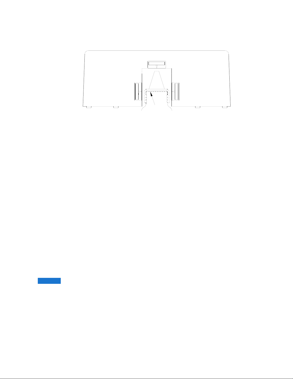
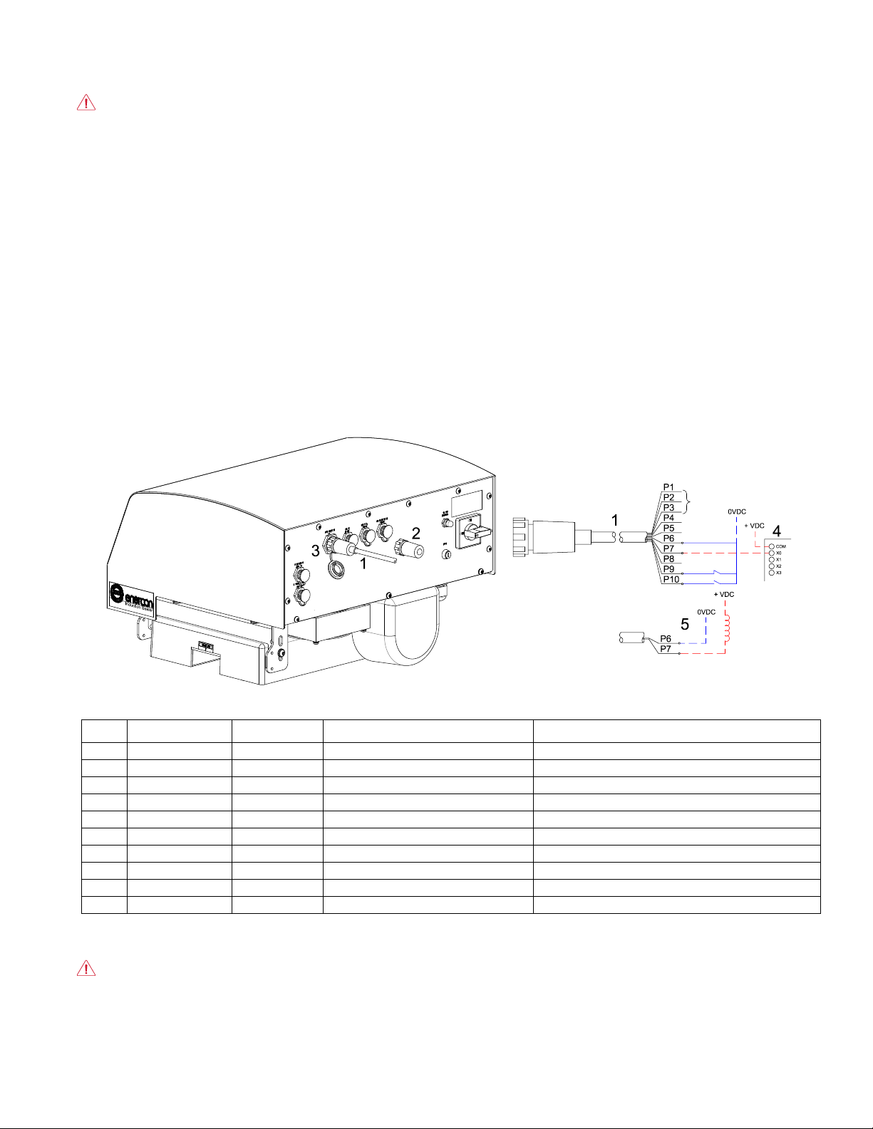
4.3 AUTOMATION I/O CABLE
Remote Start/Stop, Remote Level Control, Alarm, Ready and Customer Interlock functions require the
Automation I/O Cable [1]. Remove the defeat connector [2] and connect the I/O cable to your control and
monitoring equipment and to the AUTOMATION I/O connector [3] on the rear of the power supply (Figure 10).
Figure 10
Pin #
Cable Cores
Function
IO
Connects To:
P1
Black
Alarm N.O.
Sealer Alarm Output – Potential Free
Customer Alarm
P2
White
Alarm N.C.
Sealer Alarm Output – Potential Free
Customer Alarm
P3
Red
Alarm Com.
Sealer Alarm Common – Potential Free
Customer Alarm
P4
Blue
0-10V Out
Sealer Output
PLC – Level Control
P5
Orange
0-10V Com.
Common
PLC – Level Control
P6
Black/White
Common (0V)
Common
Interlock, Ready and Remote Start/Stop
P7
White/Black
Ready
Sealer Output
PLC – System Status
P8
Red/White
0-10V In
Sealer Input
PLC – Level Control
P9
Blue/White
Interlock
Sealer Input
Customer N.O. Dry Contact – Must Be Closed to Run
P10
Orange/Black
Start/Stop
Sealer Input
Customer N.O. Dry Contact – Close = Run / Open = Stop
Note: Alarm outputs are dry relay contacts. All other discreet outputs are transistor outputs that sink low when active. Cables
Displayed – – – – and – – – – are optional and are only required when using the Ready circuit. Contact Enercon if assistance is
needed when using the Automation I/O Cable outputs.
DANGER: Remove all external power, ensuring proper lockout / tag out procedures are followed, before
connecting or disconnecting external cables.
4.31 External Interlock
To interlock the power supply with your production line, connect the Automation I/O Cable’s Blue/White
[P9] and Black/White [P6] wires to a normally closed (N.C.), potential free interlock contact.
16
ML0185-001-01 Super Seal™ 300 / 400 / 600 Induction Cap Sealer Owner’s Reference Manual Rev. H Enercon Industries
The contact must be closed for operation, and when open, it will shut down, or prevent the power supply
from running.
NOTICE Do not apply voltage across the interlock contacts on the Automation I/O cable.
NOTE:
If an External Interlock is not provided when using the Automation I/O Cable for other functions, the
Blue/White [P9] and Black/White [P6] wires must be tied together to defeat the interlock function.
4.32 Loss of Seal Alarm
To monitor the power supply status, connect the Automation I/O Cable’s Black [P1] (N.O.), White [P2]
(N.C.) and Red [P3] (COM) wires to an external alarm or PLC. The alarm contacts are dry but should
only be wired into a circuit that does not exceed 24 volts and 3 amperes.
When the input voltage is applied, but the power supply is not running, or is running and the actual
output is outside of the alarm set point window, the alarm contacts will be in their de-energized state
(N.C. contact is closed).
When the unit is running and the actual output is within the alarm set point window, the relay contacts
will be in their energized state (N.C. contact is open).
Refer to 3.53 Alarm Setup for a detailed description on setting the alarm set point window.
4.33 Ready
To monitor the power supply readiness, use the Automation I/O Cable’s Ready signal, White/Black [P7]
and Black/White [P6] wires.
The Ready signal can be run to your PLC [4] input, to a relay coil [5], or one side of a controlled light or
alarm. When using the Ready signal, provide +24 VDC to the circuit and 0VDC to common [P6].
When the power supply is ready, the output signal will sink low to system common, to indicate ready.
NOTE:
The remaining Automation I/O Cable functions are addressed in SECTION 3 – PRINCIPLE OF
OPERATION.
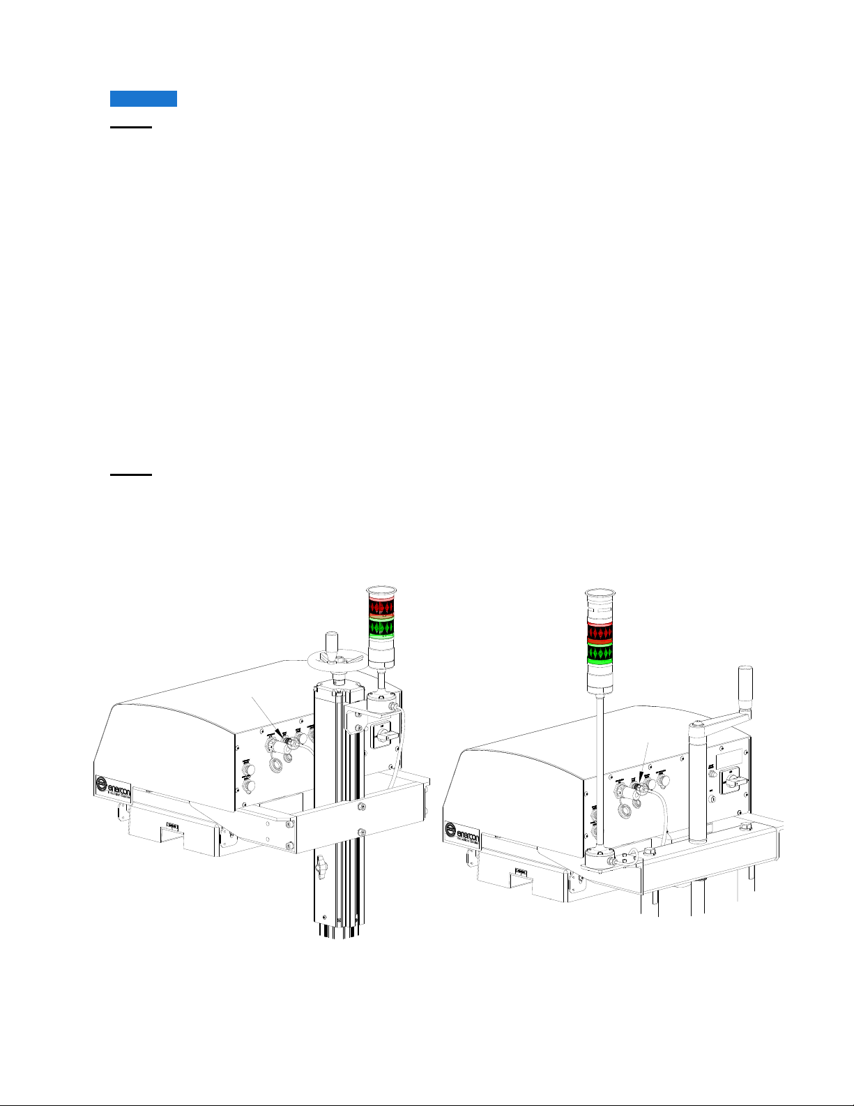
4.4 STACK LIGHT
The optional stack light provides a visual, or visual / audible indication of the power supply’s operating status, which
is pole mounted on a bracket at the top of the adjustable mount [1], or to the power supply mounting bracket
on a deluxe mobile cart [2] (Figure 11).
Figure 11
4.41 Installation
The stack light is factory mounted on both optional mobile cart systems, but must be installed on the
adjustable floor mount, refer to 2.61 Floor Mount Assembly and Figure 1 for details.
Once mounted, connect the stack light cable to the STACK LIGHT connector [3].
1
3
2
5
4
6
5
4
3
17
ML0185-001-01 Super Seal™ 300 / 400 / 600 Induction Cap Sealer Owner’s Reference Manual Rev. H Enercon Industries
4.42 Setup
For the stack light to operate as designed, you will need to ensure the Alarm Setpoint is correct, refer
to 3.53 Alarm Setup.
4.43 Operation
The standard stack light includes Green [4] and Red [5] indicator lights, and the audible stack light
includes the indicators and a buzzer [6].
Green Solid – The power supply is running, and the output is within the range of the alarm setpoint.
Red Solid – The power supply is running, and the output is below the range of the alarm setpoint.
Red Flashing – The power supply has experienced a Fault condition.
4.5 STALLED BOTTLE DETECTION
Optional stalled bottle detection allows you to automatically stop the power supply whenever a container is
detected entering the sealing head but is not detected exiting the sealing head. This prevents containers
from overheating if they stop beneath the sealing head.
WARNING: If containers stop beneath the sealing head, liners may overheat causing liner and container
contents to ignite.
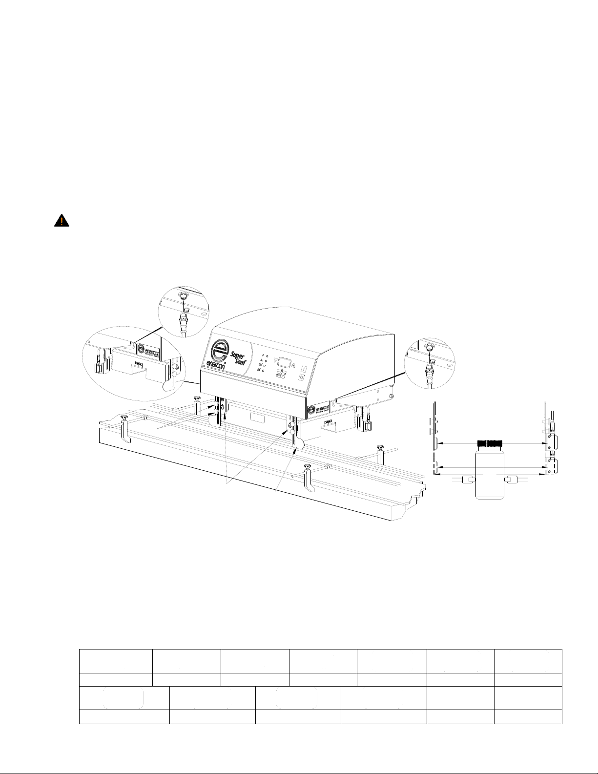
4.51 Installation and Alignment
The stalled bottle option includes 2 bracket mounted sensors [1], loose cables [2], bracket mounted
reflectors [3] and mounting hardware [4] (Figure 12).
Figure 12
Install the right hand [5] and left hand [6] sensors to the sealing head mounting brackets [7] and connect the
cables to the connectors [8] on the power supply baseplate.
With no consistent spacing between containers, align the sensor and reflector to the cap or shoulder of the
container [9], if there is consistent spacing between the containers, align the sensor and reflector to the body
of the container [10], then align the bottoms of the brackets [11].
4.52 Setup
Stalled bottle detection is setup and tested before your induction sealing system was shipped, but you will
need to set the stalled bottle timing and ensure the conveyor and sealers direction of travel match.
Menu
OK
Increase
Decrease
Display Meter
Direction
Left to Right
Right to Left
Stall
Blocked
Stalled Bottle Time
Start
Stop - Reset
1
2
4
2
1
3
8
6
5
7
11
10
9
8
Other manuals for SUPER SEAL 300
1
This manual suits for next models
2
Table of contents
Other ENERCON Food Saver manuals


