Kwik Lok 086A User manual

086A 08 08
INSTRUCTION
MANUAL
for the
TYPE 086A
and 086AS
SEMI AUTOMATIC
BAG CLOSER
TYPE SERIAL NO.
MODEL
EXECUTIVE OFFICE P.O. BOX 9548 YAKIMA, WA. 98909
TELEPHONE: 1-800- 88-5945 or (509) 248-4770
FAX: (509) 457- 531
Internet: www.kwiklok.com
CORPORATION
®
®

086A and 086AS CLOSER
TABLE OF CONTENTS
I SPECIFICATIONS.................................. 1.1 - 1.2
II OPERATION........................................... 2.1 - 2.2
III ADJUSTMENTS......................................3.1 - 3.8
IV TROUBLE SHOOTING............................4.1 - 4.3
V PARTS IDENTIFICATION....................... 5.1 - 5.8
VI WIRING........................................................6.1
APPENDIX................BAG LENGTH FORMULA
SUGGESTED SPARE PARTS
SECTION HEADING PAGE
GENERAL SAFETY INFORMATION
Be sure the following safety instructions are read, understood and become a part of daily
practice when operating or maintaining the closing head.
1. Do not attempt to operate the closer until you understand its function. Study the manual
carefully.
2. Keep all foreign material away from the drive system.
3. Keep fingers out of the closer and away from any moving parts.
4. Disconnect the power cord before making any adjustments or maintenance. All
moving parts must be completely stopped before continuing. All adjustments are made
with power disconnected.
5. The closer is normally operated from a counter or table. While the closer is very stable
when operated from a flat a solid surface, care should be taken not use it in a way that
could cause it to tip or fall from the operating surface.
® 2008 KWIK LOK CORPORATION
Kwik Lok and Striplok are trademarks of Kwik Lok Corporation ® 2008
The shape of the closure is a trademark of Kwik Lok Corporation ®2008 086A 07 08

P 1.1
SECTION I
Specifications
086A 7 01
THE TYPE 086A and 086AS
MACHINE
SEMI - AUTOMATICALLY CLOSES
PLASTIC BAGS
WITH THE STRIPLOK®CLOSURE
OR THE STRIPLOK CLOSURE LABEL
A. The closing machine designated Type 086A can
run standard R, RJ, and S series closures, and
series L and U labels.
B. The system will close a wide range of product
size variations. The Striplok closures are available
in many closure opening sizes to accommodate a
large number of variations in bag width and film
material thickness.
Upon request and upon receipt of sample bags,
the factory will gladly recommend the proper
closure opening sizes. Use the bag length formula
found in the appendix of this manual to help
determine the proper bag length needed.
C. A suggested spare parts inventory is listed in the
appendix. To save valuable time, it is recommend-
ed that an adequate supply of these parts be kept
on hand for needed repairs.

P 1.2
SECTION I
Specifications
086A SEMI-AUTOMATIC BAG CLOSING
MACHINE SPECIFICATIONS
086A 03 03
TYPE MODEL CLOSURE
086A L Labels, medium and heavy duty
U Labels, medium and heavy duty
RJ
R and S
300
400
100
200
086AS L Labels, medium and heavy duty
U Labels, medium and heavy duty
RJ
R and S
300
400
500
CR and CS Labels
CR and CS Labels
500
100
200
Up to
30 Bags/Min.
SPEED
1. The 086A semi-automatic closer comes standard
with mounted rubber feet.
Optional suction cup feet are available.
2. The 086A is available for use with the following
electrical power:
115 VAC, 60 Hz, 1.2 amp, single phase
220 - 240VAC, 50 Hz, .38 amp, single phase
3. The model 086AS is a stainless steel version of the
086 bag closer.

P 2.1
SECTION II
Operation
086A 08 08
Power switch
Ready light
Run switch
A. OPERATING SEQUENCE:
(Figure 2.1)
The closer is ready to run when the closure is in
closing position, the power switch is in the ”ON”
position, and the ”READY” light is on. When the
closed bag and closure are removed from the
closure track, the machine completes the closing
cycle placing the next closure in closing position.
The machine is again ready for the next bag.
During the completion of the closing cycle the
”READY” light will go off momentarily.
If no closure is available to move into the closing
position, the machine will continue to cycle and the
”READY light will flash repeatedly until the run
switch is turned to the ”STOP” position.
The power switch and light must be off to cut
off power to the two sensor switches. Utilizing
the power switch instead of the run switch may
result in the machine not stopping in the neutral
position as required for loading the closure
strip. Use the power switch when clearing the
machine of debris or preforming minor service
work.
1. Plug in the closer.
2. Press the power switch to ”ON”.
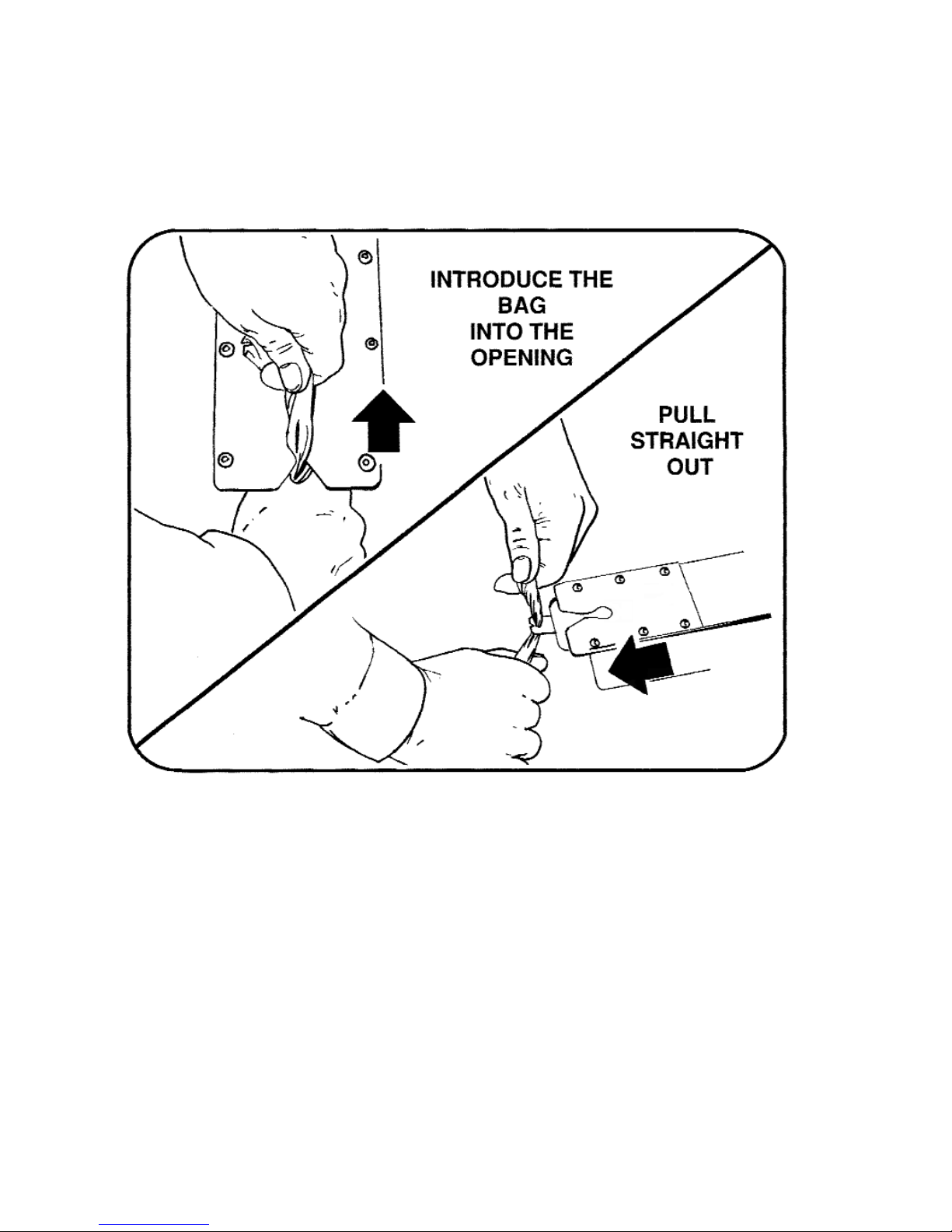
3. Slide the closure strip into the closure track until
the strip stops (refer to part B in this section).
4. Press the run switch to ”RUN” . A closure will
move into the closing position, if one is not
already there, and the ”READY” light goes on
indicating the the closer is ready to close.
5. Close the bag and remove it from the closer
(refer to part C in this section).
6. The closer cycles to position a new closure into
the closing position, ready for the next bag.
The ”READY” light will go off momentarily as
the closure is loading.
7. If no closure is available to move into the
closing position, the machine will cycle and the
”READY” light will flash on and off repeatedly
until the run switch is pressed to ”STOP”. The
machine will then cycle back to neutral and
stop. The machine at this point is again ready
to load.
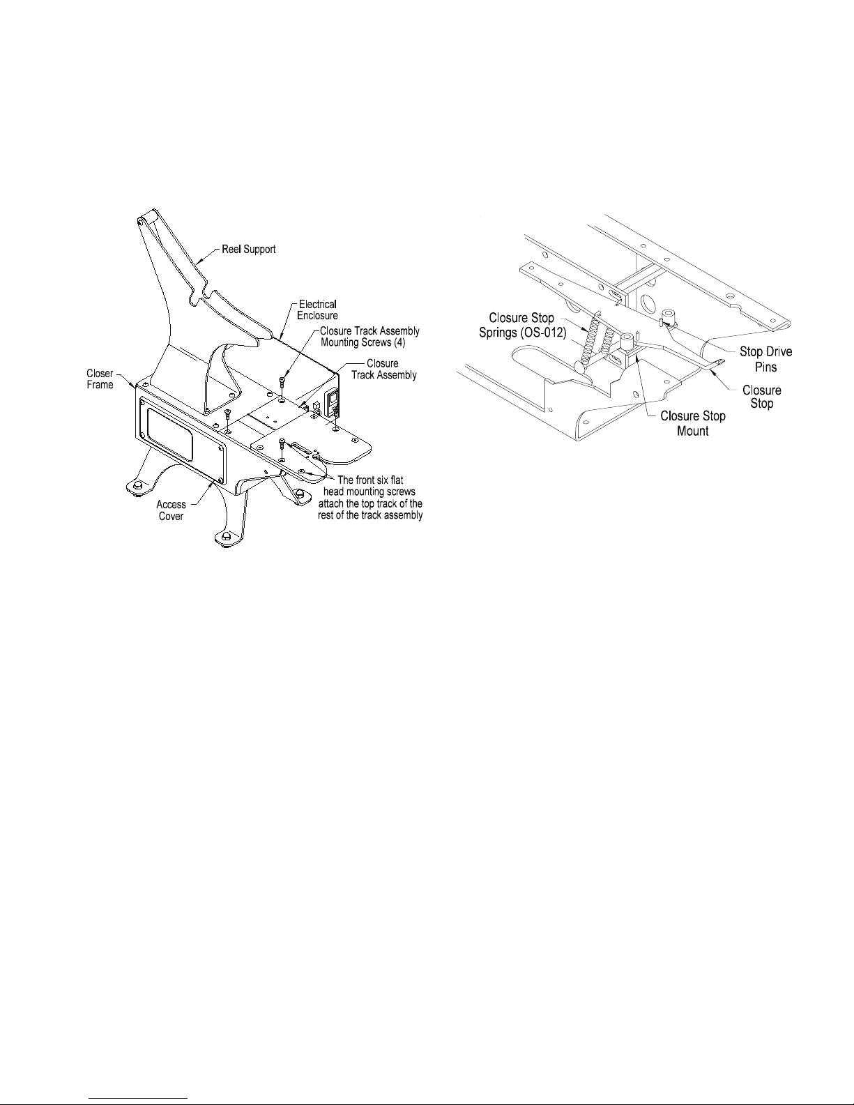
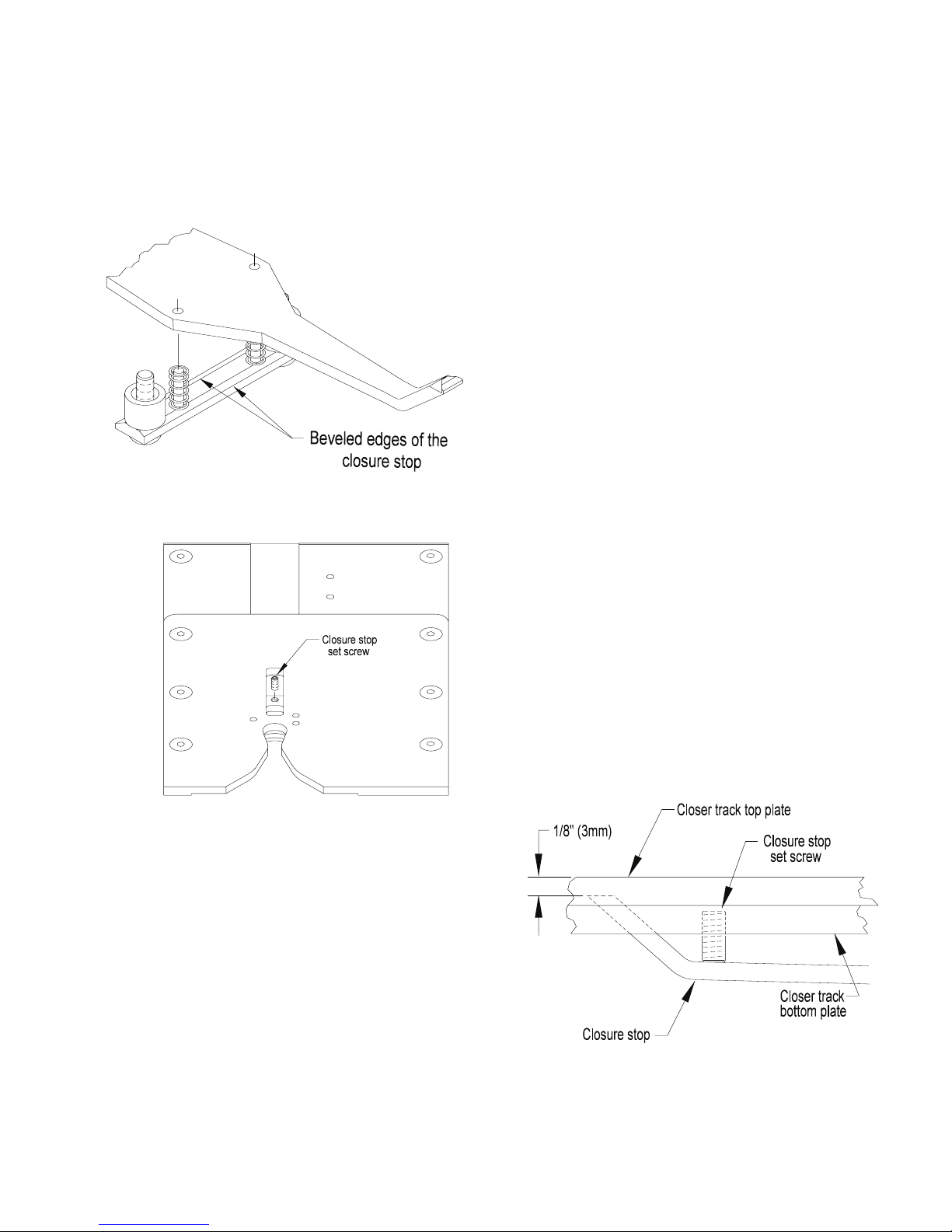
B. LOADING A ROLL OF CLOSURES:
1. Cycle the closer until there are no closures left
in the closure track. Avoid cycling the closer
more than necessary when there is no closure
in the closing position.
2. Move the run switch to “STOP” so the
mechanism is properly positioned.
3. When closing with closures, insert the closure
hub into a new roll of closures. Be certain the
closures feed forward from the bottom of the
roll.
When closing with labels, insert the closure
hub so that the label of the closure is right
side up when the closure strip is in the closure
track.
4. Install the hub and roll.
Figure 2.1

SECTION II
Operation
P2.2
5. Remove the masking tape and feed the end of
the strip into the closure track until the first
closure has passed the check and is against
the stop.
6. With the Power switch in the ”ON” position,
press the run switch to “RUN”. The closer will
cycle once and move a closure into the closing
position. The closer is now ready to close bags.
C. CLOSING BAGS:
(Figure 2.2)
1. Grasp the bag as shown. Spin the bag to twist
the bag neck. Twisting the bag helps the
material to enter the closure smoothly.
2. The lower hand should form a “V” to trap all of
the bag material. This helps to completely
insert the bag material into the closure opening.
3. Do not jam the bag material straight into the
closure opening. The top hand should lead the
bottom hand. Follow up with the lower hand
until all of the bag neck is in the closure. A tight
package is accomplished by holding the
contents of the bag snugly up against the
underside of the closure track.
4. Remove the closed bag with a horizontal
motion.
086A 08 08
Figure 2.2

SECTION III
Adjustments
P 3.1
086A 08 08
THE FOLLOWING ADJUSTMENTS ARE TO BE
PERFORMED WITH THE CLOSER ELECTRICAL
POWER DISCONNECTED.
A. CLOSURE TRACK ASSEMBLY REMOVAL:
Some of the adjustments described in this section
require removal of the closure track assembly.
1. Remove the side access cover (Figure 3.1).
2. Disconnect the two gold colored closure stop
springs (OS-012) from the lower spring anchor
screw (Figure 3.2). When the springs are
reattached be careful not to stretch them.
3. Remove the four flat head mounting screws
which attach the closure track assembly to the
closer main frame.
When remounting the track assembly, tighten
the four mounting screws evenly.
4. Lift the closure track assembly slightly and
depress the tip of the pick to disengage it from
the closure track.
5. Raise the closure track assembly slightly off the
frame and disconnect the two wire leads from
the sensor lever limit switch.
To remount the closure track assembly, reverse the
above procedure. Before closing the access cover,
check to see that there are no pinched wires or
wires routed close to moving parts.
B. TOP CLOSURE TRACK REMOVAL:
The top of the closure track can be removed from
the closer while the closure track assembly remains
attached to the closer mainframe. This can be done
to expose the slot that the closures move through.
The closure track can be inspected and cleaned if
needed (Figure 3.1).
1. Remove the front six flathead screws from the
track top. Note the different screw lengths upon
removal.
2. Remove the top of the closure track from the
rest of the track assembly.
Figure 3.2
Figure 3.1

SECTION III
Adjustments
P 3.2 086A 08 08
C. REMOVE THE FRONT SHIELD:
Some of the adjustments described in this section
require removal of the front SHIELD.
DISCONNECT POWER.
1. Remove the side access cover from the closer
frame.
2. Remove the two self tapping phillIps screws
(P23-00291) used to fasten the sides of the
SHIELD from the closer frame.
3. Loosen (turn clockwise) the two SHIELD
mounting screws at the bottom of the closer
frame.
4. Press lightly, from inside the closer frame, on
the backside of the SHIELD to remove it.
D. CHECK POSITION:
The check stops the closure strip from moving
backward while the pick retracts.
Depending on the model closer there are two
different mounting locations for the check.
Refer to Figure 3.3 to further understand the check
mounting position. For this adjustment the closure
track must be removed from the closer.
For 086 Model 100 the check is mounted in the
forward mounting holes (the two mounting holes
closest to the front of the closure track).
For 086 Models 200, 300, or 400, the check is
mounted in the back mounting holes (furthest from
the front of the closure track).
1. With the check mounted in the correct
holes, and the mounting screws loose, slide the
check forward toward the front of the closure track
to the end of the mounting slots.
2. Tighten the mounting screws.
E. CLOSURE STOP POSITION:
The end closure is separated from the closure strip
when the closure stop limits the travel of the second
closure in the strip while the pick continues to
advance the first closure.
As with the position of the check, the closure
stop mount is located in a specific way depending
on the closer model being adjusted.
1. For 086 Model 100 the closure stop mount is
mounted as shown (Figure 3.3 upper view).
Figure 3.3
Closure track assembly as viewed from the underside.

SECTION III
Adjustments
P 3.3
086A 08 08
For 086 Models 200, 300, or 400, the stop
mount is mounted as shown (Figure 3.3 lower
view).
2. Be sure the beveled edges of the mount are
against the closure stop as noted in Figure 3.4.
The closure stop tip must be centered in the slot
located in the closure track for it.
3. Slightly loosen the stop mount mounting screws.
4. Move the closure stop tip side to side until it is
centered in the slot.
5. Tighten the mounting screws.
6. Turn the closure track assembly over so it is
right side up in your hands. Again check the
position of the closure stop tip as this is the way
the closure track is oriented during operation.
Readjust if needed.
F. CLOSURE STOP SET SCREW ADJUSTMENT:
When properly adjusted the closure stop setscrew
sets the height of the stop so the second closure in
the strip is stopped while the leading closure
continues to move ahead and so is separated from
the closure strip. The closure track assembly need
not be removed to make this adjustment. Adjust as
follows:
1. Remove any closures from the track.
2. Locate the top of the set screw (Figure 3.5).
3. Turn the set screw in or out to lower or raise the
tip of the stop until it is 1/8” (3mm) below the top
of the track top plate (Figure 3.6).
Figure 3.5
Figure 3.4
Figure 3.6

SECTION III
Adjustments
P 3.4 086A 08 08
G. SENSOR LEVER SPRING:
The sensor lever spring is designed to apply force
to the sensor lever tip against the side of the closure
as well as upward against the underside of the
closure track. For the spring to operate correctly it
must be mounted as shown in Figure 3.7.
H. SENSOR LEVER STOP ADJUSTMENT
(Figures 3.8 & 3.9):
The sensor lever stop is a bushing which limits the
travel of the sensor lever when no closures are
present. The bushing is secured under a 10-32
button head screw. There is clearance between the
two so the position of the bushing can vary. When
no closures are present, the sensor lever tip should
be centered below the inspection hole in the top
track.
1. Loosen the mounting screw and move the
bushing as needed.
2. Retighten the mounting screw.
Figure 3.7
Figure 3.8
Figure 3.9
Closure track assembly as viewed from the underside.

SECTION III
Adjustments
P 3.5
086A 08 08
I. SENSOR SWITCH ADJUSTMENT:
The sensor switch detects whether or not there is a
closure in the closing position. When a closure
moves into the closing position, the sensor switch
stops the motor at the end of the cycle. When the
closure is removed, the switch starts the motor.
The switch should turn on and off midway between
the positions of the sensor lever when it is resting
against the sensor lever stop and when it is resting
against the side of a closure.
1. Check to see if the sensor lever stop is adjusted
correctly part H above.
2. Turn the closure track upside down.
3. Feed a short strip of closures (4 or 5) through
the track until the leading edge of the first
closure just slides past the sensor lever then
back out until the closure is free of the sensor
lever. Continue to slide the strip back and forth
while listening for an audible “click” indicating
that the switch is turning on and off. If the strip
of closures moves forward so far that it can’t
back up , push it out of the front of the track
and start over. Adjust if needed as follows.
4. Slightly loosen the two button head screws in
the switch mounting block (Figure 3.9).
5. Move the switch assembly toward or away from
the sensor lever. Listen for an audible “click” of
the switch as it turns on and off.
6. Tighten the mounting screws when the switch
actuates as described above.
J. MOTOR REMOVAL:
(Figure 3.10):
Any time the three button head screws which are in
the slots of the motor mounting plate are disturbed,
the pick position must be checked. See part K this
section.
The motor, motor mounting plate, cam assembly,
cam switch block and accompanying limit switch can
be removed and reinstalled as an assembly.
Component adjustment to this assembly can be
made while the assembly is out of the frame of the
closer. Remove the motor assembly as follows:
1. Disconnect power to the closer.
2. Remove the electrical enclosure cover.
3. Disconnect the two motor wires from the run
switch.
4. Remove the left side access cover from the
frame.
5. Remove the closure track assembly. See part A
in this section.
6. Remove the top plate.
7. Disconnect the pick spring (OS-117) from the
pick.
Figure 3.10

SECTION III
Adjustments
P 3.6 086A 08 08
8. Disconnect the cam switch electrical leads.
9. Remove the three mounting screws from the
slotted holes in the motor mounting plate. Refer
to part J this section for readjustment.
10. Remove the motor assembly through the top of
the closer frame.
11. To reinstall the motor assembly reverse these
steps.
K. PICK / CLOSURE LOCATION:
The pick advances the closure strip and locates the
leading closure in the bag closing position. To verify
whether the pick stops in the correct position, check
and adjust as follows:
1. Remove any closures from the closure track.
2. Verify that the pick is at the end of its travel. To
do this plug in the closer. turn the rocker switch
to “RUN” and then to “STOP”. The motor will
stop with the cam and pick in their proper
“parked” positions.
3. With the motor stopped, disconnect the power
cord.
4. Determine the correct inspection hole for the
model for your closer (Figure 3.8). The tip of
the pick should be visible in half of the
inspection hole as shown. Reposition the pick if
needed as follows:
BE SURE THE POWER IS DISCONNECTED.
5. Remove the side access cover.
6. Loosen the four button head screws mounted in
the slots of the motor mounting plate.
7. Slide the motor assembly until the pick is in the
proper position when viewed through the
inspection hole (Figure 3.8).
8. Tighten the mounting screws and again check
the pick position. Reattach the access cover.
Figure 3.11

SECTION III
Adjustments
P 3.7
L. CAM ASSEMBLY:
The cam assembly drives the pick through its cycle
and raises the closure stop at the proper time to
stop the closure strip so the leading closure can be
separated from the remaining strip. The closer cam
fastens to the outside edge of the cam hub. The
switch cam contacts the cam switch stopping the
motor and cam assembly when the pick is in the
parked or neutral position (Figure 3.13). The cam
assembly should remain on the motor shaft with no
need for adjustment. If however the cam assembly
is disassembled the following information is helpful
to reassemble it.
The cam is adjusted to drive either an 086A Model
100 or 086A Models 200, 300, and 400. Correct
assembly of the components provide the required
pick stroke so the closer functions properly. Align
the cam to the hub as follows:
1. Hold the cam so the stamped letter “R” is on the
correct side for your model closer as shown in
the appropriate view in Figure 3.11
2. Position the hub behind the cam. Rotate the
hub until one of the two 8-32 tapped holes in the
hub aligns with the countersunk hole in the cam.
3. Insert the flat head screw to secure the two
parts.
4. If the switch cam has been removed, remount it
after the cam and hub have been connected.
Square up the switch cam to the main cam hub
and then tighten into place (Figure 3.12).
5. Install the cam assembly onto the motor shaft.
Refer to part L below.
M. CAM ASSEMBLY LATERAL ALIGNMENT:
1. Set the lateral (side to side) position of the cam
assembly so the outside edge of the closer cam
measures 15/16” (24mm) from the outside edge
of the motor plate (Figure 3.12).
2. Rotate the cam assembly to position the set
screw over the flat on the motor shaft and
tighten the set screw. The angular position of
the cam assembly is not important because the
motor will stop with the cam in the correct
position when the switch cam contacts the limit
switch.
3. Tighten the set screw.
086A 08 08
Figure 3.12

SECTION III
Adjustments
P 3.8 086A 08 08
N. CAM SWITCH MOUNTING:
The cam switch allows the cam assembly to rotate
and only stop when a closure reaches the bag
closing position. The switch cam on the cam
assembly (Figure 3.13) actuates the switch. If the
rocker switch is in the “RUN” position, the “READY”
light will be on while the cam switch is actuated.
The cam switch should not need adjustment.
O. MOTOR ROTATION:
Inadvertently rotating the motor shaft manually can
damage the cam switch (Figure 3.14). If the motor
is to be manually rotated ONLY ROTATE THE
MOTOR CLOCKWISE FROM THE FAN END OF
THE MOTOR. If the motor shaft is turned in the
opposite direction (counterclockwise from the fan
end of the motor) the cam switch will likely be
damaged.
Figure 3.14
Figure 3.13

SECTION IV
Trouble Shooting
P 4.1
086A 08 08
1. The closer does not cycle
to advance a closure into
the closing position. The
light and motor are off.
2. The closer does not cycle
to advance a closure to the
closing position. The light
is off and the motor is
humming.
CAUTION: IMMEDIAT-
ELY DISCONNECT THE
POWER TO AVOID DAMA-
GING THE MOTOR. After
the problem is corrected,
the machine will complete
its cycle when the power
switch is turned on
3. The closer does not cycle
to advance a closure to the
closing position. The
power switch light is on and
the run switch is set to
”ON”. The ”READY”light
should be off.
A. Electrical power is not
available (No light on
power switch).
B. The power switch is in the
“STOP” position. No light
displayed from the ready
switch.
C. The fuse is burned out.
A.. The closures are jammed
in the closure track.
A. The motor brake is
jammed.
Connect the electrical plug to an appropriate
power source.
Press the power switch to the “RUN” position.
Check the fuse and replace as needed.
Remove any jammed closures by hand. Do not
gouge or pry on the closure track. The top of
the closure track can be removed if needed.
Refer to the Section III Adjustments for instruc-
tions.
Disconnect the power cord. Remove the elec-
trical enclosure cover. Check to see that the
brake spring is properly connected.
Check to see that the motor brake has free
movement.
If the two corrections detailed above check out
the problem in the wiring or a faulty drive motor.
PROBLEM
MECHANICAL TROUBLE SHOOTING
In the correction column of this section, any reference to a “part“ of this manual refers to the ADJUSTMENT Section
unless noted otherwise.
SYMPTOM CORRECTION

SECTION IV
Trouble Shooting
P 4.2 086A 08 08
4. The closer cycles and the
”READY” light blinks
repeatedly. There is no
closure between the check
and pick.
5. The closer cycles and the
”READY” light blinks
repeatedly. There is a
closure between the check
and pick that does not
advance.
6. The closer continues to
cycle while the switch is in
the “STOP” position. The
”READY” light does not
blink.
7. The closer cycles even
though a closure is in the
bag-closing position. One
or more closures are
pushed out the front of the
closure track.
A. The closer is operating
properly.
A. The wrong closures are
being used.
B. The check is not adjusted
properly.
C. The pick does not advance
the closure.
A. The cam switch is not
functioning properly.
A. The sensor lever is not
detecting the closure.
Move the run switch to the “STOP” position and
refer to Section II Operation, Part B, LOADING
A ROLL OF CLOSURES.
The 086A is available in four models. Refer to
the Section I Specifications to determine the
correct closure for your model closer.
See Part C. REMOVE THE FRONT SHEILD
and Part D. CHECK POSITION.
See Part C. REMOVE THE FRONT SHEILD.
Look under the front of the closure track to see
if the tips of the pick are located in the slots at
the bottom of the closure track. If it is not, cen-
ter the pick by hand. The pick is held up by the
pick spring located at the back of the pick
assembly. The pick should move down when a
light force is applied to it; when released it
should move back up due to the spring tension.
Some side play is normal when the pick is out
of the closure track slots.
The cam switch stops the motor in the proper
position and turns on the light. See Part M.
CAM SWITCH MOUNTING and SECTION VI
Wiring Diagrams. The lever of the cam switch
may be bent, the cam switch may be defective,
or the switch cam may not be mounted proper-
ly. Correct as needed.
See Part F. SENSOR LEVER SPRING, Part G.
SENSOR LEVER STOP ADJUSTMENT and
Part H. SENSOR SWITCH ADJUSTMENT.
PROBLEM SYMPTOM CORRECTION

SECTION IV
Trouble Shooting
P 4.3
086A 08 08
8. The closure in the bag-
closing position is hard to
remove because it is not
separated from the closure
strip.
9. The closure strip will not
slide freely through the
closure track.
A. The pick is not advancing
to the correct position
because the mechanism is
loose.
B. The pick is not advancing
to the correct position
because the pick is out of
adjustment.
C. The height of the closure
stop is not correct.
D. The closure stop is not
functioning correctly.
A. The closures are snagging
on the closure stop
setscrew.
B. The closure track is fouled
with foreign material.
See Part C. REMOVE THE FRONT SHEILD.
With the power cord disconnected, reach
under the front of the closure track and move
the pick downward. Grasp the pick firmly and
attempt to move it backward and forward.
Sideplay is normal. The pick assembly should
feel solid. If not the screws which mount the
pick to the pick arm or the screw that attaches
the pick arm to the closer cam may be loose or
the pick bearing may need replacement.
See Part K. PICK / CLOSURE LOCATION.
If the closure stop is not adjusted to the proper
height, the closures may slip over it. Refer to
Part F. CLOSURE STOP SETSCREW
ADJUSTMENT. Examine the closer stop to see
that it is centered in the slot in the closure track.
Refer to Part E. CLOSURE STOP POSITION.
The closure stop may move downward under
load, and may allow the closure to pass. Verify
that the two gold springs are extended between
the stop and mounting screw. Approximately
1/2 lb. (200 g) of force should be required to
depress the tip of the stop. If the upward force
is not adequate, the forward force of the clo-
sure on the tip of the stop will cause the tip to
rotate downward and allow the closure to slide
over it. The gold springs may become
stretched while they are being attached if they
are not handled carefully. Replace them if
needed.
See Part F. CLOSURE STOP SETSCREW
ADJUSTMENT.
See Part B. TOP CLOSURE TRACK
REMOVAL to open the track and clean it.
PROBLEM SYMPTOM CORRECTION


P 5.1
SECTION V
Parts Identification
086A 7 01
PARTS ORDERING PROCEDURE
IMPORTANT: When ordering parts, ALWAYS:
1) Specify on the order the TYPE, MODEL, and SERIAL NUMBER of the machine for
which the parts are being ordered. This information can be found on the machine nameplate.
2) DO NOT order by item number. Order by PART or KIT number.
To order individual parts, be sure to do the following:
1) Identify the needed parts by referring to the assembly illustrations.
Each part is assigned an item number on the illustration.
2) Refer to the parts list. Locate the item number for the part to be ordered.
Opposite the item number is the part number and description for that part.
3) Again, specify on the order the TYPE, MODEL, and SERIAL NUMBER for which the
parts are being ordered. This information is located on the machine nameplate.

P 5.2
SECTION V
Parts Identification
PARTS COMMON - STANDARD
Figure 5.1
086A 08 08
This manual suits for next models
1
Table of contents
Other Kwik Lok Food Saver manuals