Energy Carbon AirUnit Compact controller Pro Parts list manual

mfh systems
modern floor heating
mfh systems
modern floor heating
AirUnit
Compact controller Pro
Installation instructions & operating manual
List of contents, Installation instructions
Seite
1. General information ............................................................................................................................03
2. Technical Data ....................................................................................................................................04
3. Norms fulfilled ....................................................................................................................................04
4. Installation of AirUnit compact controller pro .....................................................................................04
5. Electrical connection ...........................................................................................................................05
5.1 Connection AirUnit ventilation unit(s) – AirUnit compact controller pro .............................................05
6. External digital input (bath ventilation operation) ..............................................................................06
7. Sensor operation .................................................................................................................................06
8. Settings ventilation mode ...................................................................................................................08
9. Operation amd display elements AirUnit compact controller pro ........................................................09
10. Service ................................................................................................................................................10
11. Operating hour counter ......................................................................................................................11
12. Errors ..................................................................................................................................................11
Symbols
The following symbols are used in the manual for labelling particular information:
General information / information Warning information
Information: Hazard due
to electrical voltage
Installation / maintenance information
02
1. General information
The AirUnit and controller are constructed according to state of the art technology and the recognised
safety regulations.
Installation and maintenance work of the ventilation unit may only be implemented by trained specialist
personnel under compliance with the regulations for occupational safety and accident prevention.
The electrical connection must be implemented according to VDE 0100. For installation and
maintenance work, disconnection from the mains at all poles with at least a 3 mm contact
opening width must be undertaken. The mains disconnection is to be secured against re-connection!
Use of this device is only permitted for the intended use. Incorrect usage, defectively implemented installation or
maintenance work and design changes can impair the function and safety of the ventilation unit and lead to the
termination of any warranty claims.
Prior to beginning installation / maintenance work, read this manual carefully and observe the information
provided for installation and maintenance.
Prior to the installation of the device, check the delivery with regard to completeness and integrity, and in case
of missing or damaged parts contact your supplier directly.
Intended use
AirUnit with heat recovery are designed for controlled room ventilation. The devices may only be used exclusively
for the conveyance of air. The conveyance of aggressive, flammable or extremely dusty media is not permissible.
Never operate the device without the filter which is inserted in the device.
The connection of ventilation ducts is not permissible. AirUnits are not suitable for construction drying; operation
of the device should only be implemented after completion of the construction activity.
The operation of the device in connection with fireplaces possibly requires additional safety equipment (Feuerungs-
verordnung FeuV - German Fire Code Ordinance). Corresponding information can be obtained from the chimney
sweep responsible for your region.
Device location
AirUnits may only be installed and operated indoors. When selecting the location for the device, take into
consideration that the ventilation unit is accessible for inspection and maintenance work. Installation of the device
in close proximity to flammable liquids or gases is not permissible. A mains connection (230 V / 50 Hz) is required
to the controller for operation of the device.
Installation
For the installation of the AirUnits, the recognised rules of engineering (ARdT) are to be observed with regard to
device installation, electrical work, fire protection etc. and the specifications for the ventilation of living spaces
(DIN 1946-6).
03

04
AirUnit compact controller pro
Controller 4 performance levels
Operating modes winter and summer mode
Power unit up to 4 devices
Switch range including cover frame,
cannot be combined with other swith programms
Protection type IP 20
Protection class III
Power supply 200–250Vac, 50/60 Hz
Standby power consumption < 0,5 W
Digital input 100-250Vac,50/60Hz
Bus connection RS-485, USB
Outputs 2x 12V,0,75A | 2x0-5V PWM
Dimensions 80 x 80 x 49 mm
Operating temperature 0 – 45 °C
2. Technical data
3. Norms fulfilled
The control unit conforms the safety- and health requirements of the EG guideline 2004/108/EG as well as the
EG guideline low voltage in conception and design as well as in the performance, which we have manufactured.
The following norms are considered, as far as they are applicable for that device.
• EN 61000-6-1:2007 • EN 61000-3-3:2008 • EN 61000-6-1:2007 • EN 61000-6-3:2007/A1:2011
• EN 60335-1
4. Installation AirUnit compact controller pro
The AirUnit controller is designed for the installation in a
simple cavity wall box. It can be used for the control of up
to 4 AirUnit ventilation units. The AirUnit controller is to be
connected as a stationary equipment with fixed laid cables.
Electrical connection diagram see page 06.
The supply voltage of the AirUnit controller amounts 230 V/50 Hz, as supply line a sheathed cable 3 x 1,5 mm2
(for example NYM-J 3 x 1,5 mm2) is recommended.
The control of the ventilation unit is powered by 12 V voltage (DC). The ventilation units should therefore not be
connected with the 230 V supply voltage of the control electronics. As the terminal strip for the AirUnit ventilation
units a sheathed cable of minimum 3 x 0,6 mm2is recommended.

05
5. Elektrical connection
The electrical connection must be implemented according to VDE 0100. For installation and
maintenance work, disconnection from the mains on all poles with at least 3 mm contact opening width
must be undertaken. The mains disconnection is to be secured against reconnection!
• Connection of AirUnit compact controller pro
5.1 Connection AirUnit(s) – controller
The connection of the devices occurs arranged in pairs at the plug connectors. In paired operation one device of a
device pair operates in feed mode, the second assigned device in exhaust air mode The air flow direction of both
devices is alternated at intervals.
Maximum 4 AirUnit ventilation units can be operated with the AirUnit compact controller pro. Therefore
maximum 2 AirUnit ventilation units are to be connected in parallel on plug-in connector Fan 1 and maximum 2
AirUnit ventilation units on plug-in connector Fan 2.
Those AirUnit ventilation units, which are connected on the plug-in connector Fan 1 serve as exhaust fan regar-
ding to the function “summer mode”. AirUnit ventilation units which are connected to plug-in connector Fan 2
become supply fan in “summer mode”. If several units are used, cross ventilation can be provided, e.g. to convey
cool outside air into the building during the night hours in summer.
By using a single device, the AirUnit ventilation unit can be used as supply- or exhaust fan in “summer mode”.
The connection of the AirUnits to the connection line of the controller is implemented via a plug connector
contained within the scope of delivery of the ventilation units, as depicted previously. Please observe the polarity
feed / exhaust devices (see Fig. above)!
Ventilation device Controller
+12 V – RED
PWM – PURPLE
Gnd – BLUE
RED – +12 V
PURPLE – PWM
BLUE – Gnd
Connecting terminal
1 RS485-A
2 RS485-B
3 12V Bus
4 GND
5 12V
6PWM A
7 GND
8 12V
9 PWM B
10 GND
Net terminal
1L1
2N
3
External Input L1´
must be in phase
with L1!
Abluft Zuluft

06
6. External digital input (bath fan operation)
ATTENTION
It is mandatory that the input as well as the ventilation unit are supplied electrically from the
same phase, otherwise an impermissibly high voltage and therefore the destruction of the device
may occur.
Alternative air performances
The external digital input is a 230 Vac input
and can be used as an offset of exhaust
volume flows for the operation bath
ventilators.
The external input is connected in parallel
to the bath fan. Make sure, that bath fan
and ventilation unit are switched in the
same phase! While the bath fan is in use, a
dysbalance of supply air power 30 m3/h and
exhaust duct 15 m3/h per device is being
used instead of the standard air performan-
ce, whereby the exhaust air volume flow of
the bath fan can be compensated.
Abluft Zuluft
NL1
L1´
L1´
Light switch
L1
7. Sensor operation
Controller
...
up to
Sensor 1 Sensor 4
BUS
A
1
B
2
+
3
-
4
BUS
A
1
B
2
+
3
-
4

07
Via the integrated bus-interface of the device different air quality sensors (max. 4 sensors) of the controller can be
switched off. The digital air quality sensors send their measured values to the controller. Based on these values the
ventilation unit can increase or reduce the air stages, if required.
The number of connected sensors has to be established via the control element (see graph).
The type of the sensor will be automatically detected and then, the suitable threshold values will be used.
Depending on the air quality (e.g. air humidity) the air stages will be automatically increased or reduced. If the air
stages will be reduced manually, the demand-based ventilation system will be deactivated for a period of 60 minutes.
The number of the used sensors has to be set in accordance with the following graphs.
Keep both switches pressed simultaneously for 5
seconds, to enter the configuration menu.
By single pressing the left button, the combination of
the left LEDs must be selected as shown.
APress long for saving.
Flashes when successfully saved.
BPress long for leaving the configuration menu.
By single pressing the right button (arrow UP / arrow
DOWN) the combination of the right LEDs must be
selected as shown.
1
3
2
AN
AN
BLINKEN
A
B
4
No sensor
OFF
OFF
ON
OFF
Three sensors
ON
OFF
OFF
OFF
Four sensors
ON
OFF
ON
OFF
One sensor
OFF
ON
OFF
OFF
Two sensors
OFF
ON
ON
OFF

08
• Function summer mode (feed or exhaust air mode without heat recovery):
The AirUnit(s) operate constantly in feed* or exhaust air mode*; in this setting, heat recovery does not take place.
A change to winter operation with heat recovery occurs automatically after 8 hours.
*Der Betriebsmodus wird durch den Elektroanschluss definiert, das Gerät kann als Zu- oder Abluftgerät an der
AirUnit Regelung angeschlossen werden (see Electrical connection page 06).
• The winter mode function (feed or exhaust air mode with heat recovery):
The AirUnit(s) operate alternately in 2 adjustable time intervals. In the first interval (exhaust air phase) the „used“
room air is extracted outside via the ventilation unit. In the process, the air flows through the ceramic heat accumula-
tor, which absorbs and stores the heat of the room air. In the second interval (feed phase) the „fresh“ outside air is
conveyed into the room via the ventilation unit. The outside air similarly flows through the heat accumulator, absorbs
the previously stored heat and introduces this back into the room. In case of AirUnit operating in pairs, the devices of
the device pair work in opposite directions, i.e. the first device in feed and the second device in exhaust air mode;
in the next interval this is vice versa. In this way, a heat recovery of up to 90% occurserfolgt eine Wärmerückgewin-
nung von bis zu 90%.
•AirUnit ventilation system with 2 feed and 2 exhaust air units:
Feed devices in „summer mode“ Exhaust devices in „summer mode“
8. Einstellungen Lüftungsbetrieb
The operating mode variants of the AirUnit ventilation units are adjusted via the operating panel of the
controller. Two basic functions with different ventilator performance can be set:
Function summer mode (without heat recovery)) →
Function winter mode (with heat recovery)) →
09
The device is set to feed or exhaust air mode
2
without heat recovery (= summer mode by pressing
this button. The summer mode is automatically reset to winter mode 8 hours after activation.
Summer mode is extended by a further 8 hours by actuating this button again.
2
Is dependent on the electrical connection, see page 06
The device is set to alternate feed / exhaust air mode with heat recovery (winter mode) by pressing
this button. During the heating period, the device should be constantly operated in this setting.
If the adjacent symbol lights up, then the device is in performance level 3. Performance level 3
is automatically reset to performance level 2 an hour after its activation. If the adjacent
symbol pulsates, the device is controlled in sensor operation.
If the adjacent symbol lights up, then the device is in performance level 2. If the adjacent
symbol pulsates, the device is controlled in sensor operation.
If the adjacent symbol lights up, then the device is in performance level 1. If the adjacent
symbol pulsates, the device is controlled in sensor operation.
If the adjacent symbol lights up, then the device is in performance level minimum ventilation.
By actuating “DOWN”, the device is switched off and the symbol pulsates quickly. If the adjacent
symbol pulsates, the device is controlled in sensor operation.
Constant illumination of this display indicates that inspection / cleaning of the filter insert of the
ventilation unit is due. The maintenance of the filter inserts is described on page 11. If this display
flashes, it signalises a malfunction on the control panel of the controller. The control electronics
or the control panel must be checked by an electrician, see Malfunction page 12.
The device is switched on to performance level 1 by pressing this button. By pressing the button
again, the next-higher performance level is selected.
The device is reset to the next lower performance level by pressing this button. If the device is at
minimum ventilation, then the device is switched off by pressing this button again.
Sleep-Timer Funktion: The sleep timer is activated by pressing and holding the button. This
display of the performance level is maintained and the bottom LED is pulsing. After two hours, the
device switches back to the last selected performance level. A touch of the upward button deletes
the sleep timer and switches the device back into normal operation.
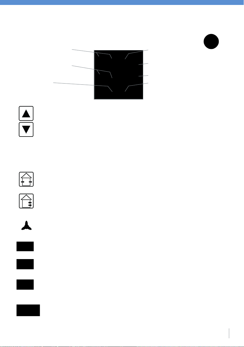
9. Operating and display elements of the compact controller pro
Function key / signal lamp
„summer mode” (without heat recovery)
Signal lamps
„Performance level 1-3”
Function key „Performance level DOWN“
Function key „Performance level UP“
Signal lamp „OFF / minimum ventilation“
Function key / signal lamp
„winter mode” (with heat recovery)
Signal lamp
„Filter change / fault”
10
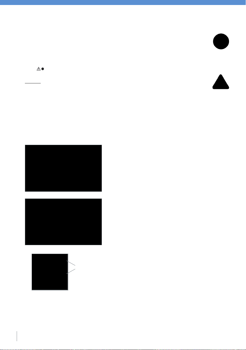
10. Maintenance filter insert
The filter inserted into the ventilation unit is monitored in the control electronics by means of an operation
time measurement. After the expiry of 3 months continuous operation (2190 operation hours), the required
inspection of the filter insert is indicated on the control panel of the controller when the signal lamp „Filter change /
fault“ is continuously lit up. Checking / cleaning of the filter insert is described below.
Caution:
Prior to all maintenance work, the power supply of the ventilation unit must be interrupted at all
poles. The mains disconnection must be secured against reconnection!
To check the filter, the inner screen of the ventilation unit must be pulled off in an upward direction. The plug connection
of the connection line is to be disconnected and the sound insulation mat removed. Subsequently, the ventilator unit can
be removed from the wall duct. Pull the wire assembly backwards out of the housing pipe and remove the filter for any
cleaning work due.
In case of slight contamination (no or little dust deposition),
the filter insert can be vacuumed or beaten clean. In case of heavy
contamination, the filter insert can be washed using warm water
(approx. 40° C) and a conventional household mild detergent.
In the process, the filter should not be tumbled if possible. Allow
the cleaned filter insert to dry completely prior to reinsertion
into the ventilation unit; dust deposits will occur immediately on
a damp filter! In order to ensure continued good filtration, a filter
replacement is necessary at the latest with the destruction of the
fibre structure. Insert the dried filter insert into the ventilator unit
again and assemble the AirUnit ventilation unit in the reverse
order. After the inspection / cleaning of the filter insert and
switch-on of the power supply for the AirUnit, the operation time
measurement must be restarted for monitoring the filter insert.
Restart occurs via the control panel of the controller:
Restart of the operation time measurement occurs by simultaneously
pressing the buttons „UP“ and „DOWN“. Hold down both buttons
until the red LED „Filter change / fault“ goes off (approx. 5 seconds).
The re-start of the filter monitoring can be implemented as described
above, also without prior output from the filter change display, e.g.
within the scope of a scheduled inspection.
The prompt for a filter check is issued dependent on time after a 3-month operation period; the actual
contamination level of the filter is not taken into consideration. Depending on the level of contamination,
an earlier filter replacement may be expedient. It is therefore recommended that you check the filter insert at
three-month intervals in the first year after commissioning the AirUnit, and in case of recognisable heavy
contamination of the filters, that you reduce the inspection / cleaning intervals.
• Filter insert removal
5 seconds

11
11. Operating hours counter
12. Errors
No. Error Blink-Code Measure
1 Filter change necessary Light indicates
2 Self-test-error 2 flashes – pause
3
Communication disturbance sensor
3 flashes – pause
4 Temperature-error 4 flashes – pause
The ventilation system has an integrated operating hours counter.
The display of the operating hours shows the sum of the operating hours during which the device was operated in an
air stage of at least the moisture protection. The display is based on the number of flashing pulses of the individual
LEDs. The LED for moisture protection represents the 10th digit of the operating hours. The reduced ventilation led is
the 100 digit. The led for the nominal ventilation is the 1000 digit. The Led for the intensive ventilation the 10000er
digit. The number of flashing pulses ranges from 0 to 9 and the LEDs flash through their flashing patterns starting
from the lowest one in sequence. After one run, the display starts again with the 10 digit.
10.000 digit
1.000 digit
100 digit
10 digit
Keep both switches pressed simultaneously for
5 seconds, to enter the configuration menu.
By single pressing the left button, the combination of
the left LEDs must be selected as shown.
APress and hold to exit the configuration menu.
1
3
2
AN
AN
AN
A
4

Table of contents
Popular Fan manuals by other brands

Polypipe
Polypipe Silavent GLA100LV installation instructions

emerio
emerio TFN-214473.4 instruction manual

Viessmann
Viessmann VITOVENT 300 Technical guide

Somogyi Elektronic
Somogyi Elektronic home TF32/BK instruction manual

Marta
Marta MT-FN2544 user manual

Vallox
Vallox 70 COMPACT R Instructions for use and maintenance
 owner's manual")


