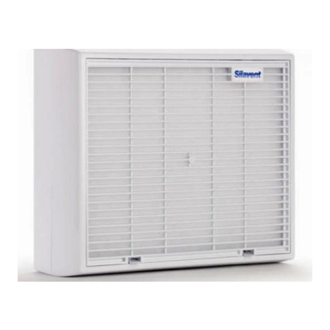
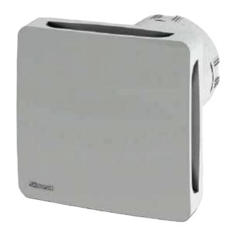
Polypipe Silavent GLA100LV User manual

Email: [email protected]
Installation Instructions
Silavent Green Line
Energy Efficient
GLA100LV SELV Axial Wall/Window
&
GLD100 In-line Axial Fans
1
Website: www.polypipe.com/ventilation
LAB447R, Issue 5, March 2013

Website: www.polypipe.com/ventilation
LAB447R, Issue 5, March 2013
Silavent Green Line
Energy Efficient GLA100LV Axial Wall/Window Fans & GLD100 In-line Axial Fans
These high quality extractor fans are designed to provide effective ventilation and in order to achieve this,
please read these instructions carefully BEFORE installing the fan unit. Failure to comply with these
instructions could reduce the life of the product and may invalidate the warranty.
These products are suitable for use with up to a maximum of 1.5m of ducting.
This appliance is not intended for use by persons (including children) with reduced physical, sensory or mental
capabilities, or lack of experience and knowledge, unless they have been given supervision or instruction
concerning use of the appliance by a person responsible for their safety.
WARNING: ISOLATE ELECTRICITY SUPPLY BEFORE STARTING WORK
Fitting into a wall
1. Select a suitable position for the fan that keeps the duct as short and as straight as possible.
2. Select a suitable position for the fan power supply box ensuring it is outside of zone 2. Remove the cover
and secure to a surface using suitable fixings (not supplied)
3. Connect the power supply cable to the power supply box and prepare and connect a second piece of
cable to link the power supply box to the fan (see wiring diagrams).
4. Cut a hole in the wall to suit the outside diameter of the ducting or wall-liner. Install the duct or wall-liner
taking care to seal at both ends between it and the wall.
5. Remove the front cover of the fan by undoing the retaining screw at the bottom edge of the front cover.
Position the fan back-plate and mark the retaining screw positions.
6. Remove the appropriate cable entry knock-out position from the fan back-plate and thread power cable
through before fixing the fan to the wall using appropriate fixings (not supplied).
7. To complete the installation fit an external grille to the outside wall.
Fitting into a ceiling
1. Select a suitable position for the fan that keeps the duct as short and as straight as possible.
2. Select a suitable position for the fans power supply box ensuring it is outside of zone 2. Remove the
cover and secure to a surface using suitable fixings (not supplied)
3. Connect the power supply cable to the power supply box and prepare and connect a second piece of
cable to link the power supply box to the fan (see wiring diagrams).
4. Cut a 100mm (4”) hole in the ceiling to suit the outside diameter of the fan spigot.
5. Remove the front cover of the fan by undoing the retaining screw at the bottom edge of the front cover.
Position the fan back-plate and mark the retaining screw positions.
6. Remove the appropriate cable entry knock-out position from the fan back-plate and thread power cable
through before fixing the fan to the ceiling using appropriate fixings (not supplied).
7. To complete the installation fit duct and a suitable external grille to the outside wall/soffit in accordance
with the wall fitting instructions above. Alternatively a roof terminal may be used; however a Domus 497
condensation trap should be fitted to any vertical duct.
Note: Fans fitted with pull-cord switches are not suitable for ceiling mounting.
Fitting into a window
1. Use window fixing kit Silavent SDF901WFK – follow instructions supplied with kit.
Fitting an In-line Fan
1. Select a suitable position for the fan that keeps the duct as short and as straight as possible.
2. Select a suitable position for the fans power supply box. Remove the cover and secure to a surface using
suitable fixings (not supplied)

Email: [email protected]
3. Connect the power supply cable to the power supply box and prepare and connect a second piece of
cable to link the power supply box to the fan (see wiring diagrams).
4. Remove the domed centre cover from the fan by removing the single screw.
5. Cut an incision into the blanking plug and feed the supply cable through. Connect the cable to the correct
terminals. (see wiring diagrams).
6. Ensure the fan is moving air in the correct direction and bring the duct system to each end of the fan.
Secure the fan to a surface using suitable fixings and seal the duct connections.
Note: All ancillary items can be obtained through Silavent stockists.
Call +44 (0) 8443 715523 to find your nearest stockist
Wiring Instructions:
It is recommended that the fans are connected into the lighting circuit, with double pole isolation (3mm
minimum contact separation) provided before the room light switch and suitably fused, in accordance with the
latest edition of the IEE Wiring Regulations.
Window mounted fans should be connected to the power supply using a flexible cord with conductors of
maximum size 0.75mm². Wall and ceiling mounted and In-line fans for fixed wiring should be connected to the
power supply through a cable with solid conductors of between 1.0mm² and 1.5mm² only.
IF IN ANY DOUBT CONSULT A QUALIFIED ELECTRICIAN
Models
GLA100LV-T
GLA100LV–S GLA100LV-H
GLA100-PIR
GLA100LV-PC GLA100LV-HPC
GLD100-T
S/L OR T = Switched Live L = Permanent Live N = Neutral
WARNING: ISOLATE ELECTRICITY SUPPLY BEFORE STARTING WORK
MAXIMUM ROOM TEMPERATURE 40ºC
3
Website: www.polypipe.com/ventilation
LAB447R, Issue 5, March 2013

Website: www.polypipe.com/ventilation
LAB447R, Issue 5, March 2013
Range:
GLA100LV-S SELV Axial Wall Fan Standard
GLA100LV-T SELV Axial Wall Fan Overrun timer
GLA100LV-PC SELV Axial Wall Fan Integral pull-cord switch
GLA100LV-H SELV Axial Wall Fan Humidistat and optional overrun timer
GLA100LV-HPC SELV Axial Wall Fan Humidistat and optional overrun timer and pull-cord switch
override
GLA100LV-PIR SELV Axial Wall Fan Movement detection with overrun timer
GLD100-T In-line Axial Fan Overrun Timer
All of the above wall mounted models are available with integrated backdraught shutters. Add ‘BS’ to the end
of the codes above to specify backdraught shutters.
OPERATION
Overrun timer adjustment – models fitted with overrun timers only
Before making any adjustments, isolate the fan from the power supply. Remove the front cover and the inner
cover. The overrun timer is factory set at mid-point (approximately 15 minutes); to reduce the overrun time,
turn anti-clockwise (minimum overrun is approximately 1 minute); to increase the overrun time, turn clockwise
(maximum overrun is approximately 30 minutes). Refit both covers before switching on the power supply.
Humidity adjustment – humidistat models only
All GLA humidistat fans automatically sense a change in humidity and adjust accordingly. The humidity control
does not require to be manually adjusted.
Rating: 230V 50Hz 4W IPX4
This product is double insulated and does not require an earth conductor.
Contact address:
Polypipe Ventilation
Sandall Stones Road
Kirk Sandall Industrial Estate
Kirk Sandall, Doncaster
DN3 1QR
Tel: +44 (0)8443 715523
Fax: +44 (0)8443 715524
International Tel: +44 (0)1302 348878
International Fax: +44 (0)1302 348879
This manual suits for next models
8
Table of contents
Other Polypipe Fan manuals
Popular Fan manuals by other brands

G3 Ferrari
G3 Ferrari TOTAL BLACK REMOTE user manual

DAY
DAY 73212 instruction manual

All Seasons Hire
All Seasons Hire Cyclone 30 operating instructions

LUCCI Air
LUCCI Air AIRFUSION MOTO LD-MOTO-52 Installation operation maintenance warranty manual

Eberg
Eberg BRIS instruction manual

Dometic
Dometic GY20 Instructions for use