manuals.online logo
Brands
  1. Home
  2. •
  3. Brands
  4. •
  5. ENERGY KINETICS
  6. •
  7. Boiler
  8. •
  9. ENERGY KINETICS Accel CS User manual

ENERGY KINETICS Accel CS User manual

Accel CS™
Installation Guide
Energy Kinetics Inc. 51 Molasses Hill Rd. Lebanon, NJ 08833 800-323-2066 www.energykinetics.com
X:\TechDocs\Installation_Manuals\AccelCS_Quick_Install_Guide\AccelCS Quick Install Guide 02-26-19.doc
We have attempted to make your installation of the Accel CS boiler easy by pre-piping and pre-wiring a
complete system.
Note: These instructions are for quick reference only.
For complete instructions, refer to “Owner and Installation Manual” found inside top front cover.
Install Circulator to supply
flange. Bolts, gaskets and
flange located in component
box.
Return: Right termination
Use included 1” x 9” nipple
Return: Left termination
Use included 1” x 18” Nipple
Gas, Return and Drain Pi
p
in
g
Premier System: Install ½”
nipple, & Combo Boiler
Feed/Backflow Preventer
Stainless steel vent
w/ built in test port
2”/3” Direct Air Inlet
See diagram pg 2 fig A
3x2 Adaptor
for 2” venting
Insert into 3”PPS
adaptor. DO NOT
INSERT DIRECTLY
INTO STAINLESS
CONNECTION
Gas: Ri
g
ht termination
Gas: Rear termination
Condensate Trap: Fill with water prior to
startup. Make sure trap ball floats freely
before completing install.
Install Air Vent & Relief Valve
Remove hygroscopic air vent cap
when purging the system, and hand
tighten when placing into service.
3” Appliance adaptor
Use for all PPs
venting.
Accel CS Installation Instructions
Page 2
Energy Kinetics Inc. 51 Molasses Hill Rd. Lebanon, NJ 08833 800-323-2066 www.energykinetics.com
X:\TechDocs\Installation_Manuals\AccelCS_Quick_Install_Guide\AccelCS Quick Install Guide 02-26-19.doc
Zone Valve for PHE
(Locate on boiler supply)
LEBANON,NJ08833
C
H
ColdWaterSupply
006BronzeCirculator
w/IntegralFlowCheck
See"SmartPumpWiring".
BackflushDrain
PHE(PlateHeatExchanger)
Pipeboilersideandtankside
counterflow.
DipTubeinColdport
HeatTrap
HotWater
toHouse
ComboTee/Drain
SmartPumpAssembly
Adaptor3/4"FTGXM
Tee3/4"X1/2"X3/4"
Boiler Side Backflush (Optional)
1
2" Ball Valve
Partially closing this valve will slow
the flow through the PHE and
increase the water temperature
entering the tank.
Use 3
4" Copper to pipe
boiler side of PHE
PREMIER SYSTEM:
Heat & Hot Wate
r
Hot Water Box
Smart pump with harness,
plate heat exchanger with
unions, fittings bag, zone valve
and hot water manual.
P
Premier System: (2) 1” headers
with (5) ¾” ports, (2) C x M
adaptors, (2) ¾” copper caps.
Component Box
Boiler circulator, trap,
fittings bag, CO & gas
detector, Manager box
and manual.
Fittings bag
Smart thread sealant,
relief valve, air vent with
tubing, boiler drain,
nipple, ¾” tee, 1”x1”x3/4” tee,
bushing, circ. flange w/bolts.
Premier Box
(3) zone valves,
combo boiler feed/backflow
preventer and 8-Way treatment.
Tips:
1)Tighten all boiler stand screws
before moving.
2)Remove stand front panel for easier
piping access after boiler is set in
place. Keep yellow panels in place
when piping under boiler. Re-install
boiler stand
p
anel when com
p
lete.
4 Way Intake Boot: May be piped using
polypropylene ( mfg. by Centrotherm or
Durovent) or PVC. Refer to installation manual
to determine the proper intake size.
3” Polypropylene 2” Polypropylene
2” PVC w/field
supplied coupling 3” PVC w/field
supplied coupling
Figure A
Accel CS Installation Instructions
Page 3
Energy Kinetics Inc. 51 Molasses Hill Rd. Lebanon, NJ 08833 800-323-2066 www.energykinetics.com
X:\TechDocs\Installation_Manuals\AccelCS_Quick_Install_Guide\AccelCS Quick Install Guide 02-26-19.doc
Hot Water Storage Tank Pump Wiring and Piping
VENTING:
Refer to Owner and Installation Manual WARNING: Leak test all gas connections
including factory connections.
Cold Water Make Up IN
OPTION SWITCHES: Refer to
Owner and Installation Manual.
H C
Hot (Black)
120 V
Hot Water OUT
(Heat Trap Optional)
A1 T1
T2
T4
Z3
24 VAC
A1
Pigtail
Boiler IN
Boiler OUT
Smart Pump to
Domestic IN
Domestic OUT
Neutral to an open
120VAC neutral terminal
Violet pigtail to120VAC
DHW CIRC terminal
Neutral
(White)
LINE VOLTAGE WIRING: The line voltage wiring is
essentially complete in the wiring harness junction
box.
Connect 120 VAC power to pigtails provided.
Outdoor Sensor:
Install sensor on North side
of dwelling with cable inlet
facing down.
Install leads in Block J-8
Positions 11 & 12
22AWG/100
fjkjk hkk j i2
OR
Sola
24 VAC
Pigtail
T1, T2, T3, T4
Z1, Z2, Z3, Z4
Ground
(Green)
J-8
TIP: Run the Smart Pump
greenfield through the bottom of
the Accel for a cleaner look and
shorter wiring run.
Option Switch 5 OFF: Max./min. boiler supply setting 160°F/120°F
Option Switch 5 ON : Max./min. boiler supply setting 180°F/140°F.
Option Switch 4 ON : Set Custom max./min. boiler supply temps
O
p
tion Switch 9 ON : Indirect tank with coil
(
OFF: Plate Heat Exch
)
Accel CS Installation Instructions
Page 4
Energy Kinetics Inc. 51 Molasses Hill Rd. Lebanon, NJ 08833 800-323-2066 www.energykinetics.com
X:\TechDocs\Installation_Manuals\AccelCS_Quick_Install_Guide\AccelCS Quick Install Guide 02-26-19.doc
ADJUSTMENTS
Check gas supply pressure to the appliance using a manometer connected to the inlet pressure tap.
Start boiler. To prevent the burner from modulating use the domestic hot water demand or a large volume central heat
zone.
Check gas supply pressure to the appliance a second time using a manometer connected to the inlet pressure tap.
Using combustion test equipment, insert the probe into the exhaust gas outlet (flue port)
Fuel Adjustment Procedure
Gas pressure range
Natural 3.5” - 10.5”w.c.
LPG 8”
–
13”w.c.
Set max outdoor temp: INFO buttonQuick StartMax Outdoor Temp
Set min outdoor temp: INFO buttonQuick StartMin Outdoor Temp
If the INFO Test screen displays two
options (Forced Rate, Manual Pump
Operation), use Method 1 on the following
page.
If the INFO Test screen displays three
options (Forced Rate, Manual Burner
Operation, Manual Pump Operation), use
Method 2 on the following page. NOTE: Do
not use the “Manual Burner Operation”
menu.
Accel CS Installation Instructions
Page 5
Energy Kinetics Inc. 51 Molasses Hill Rd. Lebanon, NJ 08833 800-323-2066 www.energykinetics.com
X:\TechDocs\Installation_Manuals\AccelCS_Quick_Install_Guide\AccelCS Quick Install Guide 02-26-19.doc
Fuel Adjustment Method 1
1. Start appliance
2. Run appliance at maximum fan speed (See Table in Boiler manual for specific model): INFO buttonAdvanced
SetupModulation Config. Use left and right arrows only. To delete prior setting, arrow to DEL and press OK
repeatedly until cleared, then use arrows to enter maximum RPM.
3. Check that O2 reading is 4.5% and adjust throttle screw if necessary. Turn throttle screw clockwise to increase
O2 and counter clockwise to decrease O2.
4. Keep appliance running until completely stabilized, make adjustment when necessary.
Offset adjustment
5. Set appliance to minimum fan speed (See Table in Boiler manual for specific model): INFO buttonAdvanced
SetupModulation Config. Use left and right arrows only. To delete prior setting arrow to DEL and press OK
repeatedly until cleared, then use arrows to enter minimum RPM.
6. Remove cap screw with a Torx T-40 screw driver or 5 mm hex key to expose offset adjustment screw
7. Check that offset O2 reading is 4.5% and adjust if necessary. Turn counter clockwise to increase O2 and
clockwise to decrease O2 reading. Adjust in very small increments, and allow to stabilize between adjustments.
8. Reset appliance fan speed to maximum RPM (see Item 2 above). Verify speed is at max RPM. To view current
fan speed, press “Home”.
9. Perform carbon monoxide test two minutes after light off. If the carbon monoxide exceeds 400 ppm air-free after
two minutes of operation, shut off boiler immediately and repeat "Prepare for Start Up" checklist found in
installation manual.
Repeat steps 1 to 6 when adjustment of offset pressure is necessary, resetting fan speed to maximum.
Fuel Adjustment Method 2
1. Start appliance
2. NOTE: Do not use the “Manual Burner Operation” menu. Using this feature may result in unintended and
undesired behavior.
3. Set appliance maximum and minimum fan speed (See Table in Boiler manual for specific model): INFO
buttonAdvanced SetupModulation Config. Use left and right arrows only. To delete prior setting, arrow to
DEL and press OK repeatedly until cleared, then use arrows to enter RPMs.
4. Navigate to test mode menu: INFO Test Forced Rate. Select “Set Low Fire”, wait (2) seconds to be sure
“Manual firing rate” displays the desired fan speed. Repeat with “Set High Fire”. Select “Start Test”.
5. Check that O2 reading is 4.5% and adjust throttle screw if necessary. Turn throttle screw clockwise to increase
O2 and counter clockwise to decrease O2.
6. Keep appliance running until completely stabilized, make adjustment when necessary.
Offset adjustment
7. Set appliance to minimum fire by selecting “Set Low Rate”.
8. Remove cap screw with a Torx T-40 screw driver or 5 mm hex key to expose offset adjustment screw
9. Check that offset O2 reading is 4.5% and adjust if necessary. Turn counter clockwise to increase O2 and
clockwise to decrease O2 reading. Adjust in very small increments, and allow to stabilize between adjustments.
10. Reset appliance fan speed to max RPMs (see Item 2 above). Verify “Manual firing rate” displays correct RPM.
11. Perform carbon monoxide test two minutes after light off. If the carbon monoxide exceeds 400 ppm air-free after
two minutes of operation, shut off boiler immediately and repeat "Prepare for Start Up" checklist found in
installation manual.
Repeat from 1 to 6 inclusive when adjustment of offset pressure was necessary, resetting maximum fire to 6000
RPM, or 5000 RPM for an EK2C.
NOTE: Setting the fan speed outside the recommended range may cause a lockout.
After adjustments are made, stop appliance, disconnect pressure gauge and combustion analyzer. Make sure to tighten
inlet pressure tap, offset cap screw and combustion test port.
Final checkout of the installation
Refer to Installation and Service Manual for final checkout. After any adjustment, set appliance in operation. Observe
several complete cycles to ensure that all burner components function correctly.

Other ENERGY KINETICS Boiler manuals

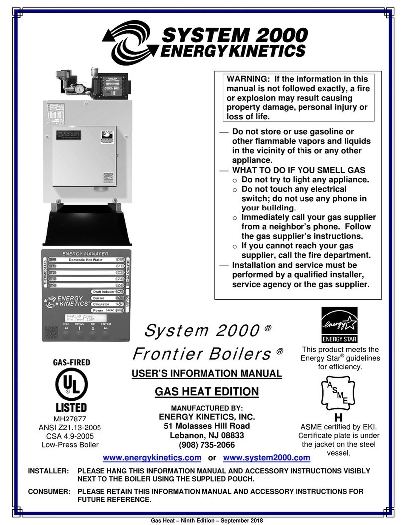
ENERGY KINETICS System 2000 Guide

ENERGY KINETICS

ENERGY KINETICS System 2000 Guide

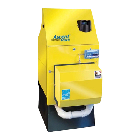
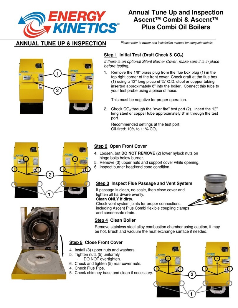
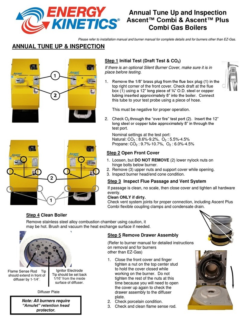
ENERGY KINETICS Ascent Combi Boilers Guide

ENERGY KINETICS

ENERGY KINETICS Ascent Combi Boilers Guide

ENERGY KINETICS RESOLUTE RT Service manual

ENERGY KINETICS

ENERGY KINETICS RESOLUTE RT Service manual

ENERGY KINETICS EK1 Frontier User manual

ENERGY KINETICS

ENERGY KINETICS EK1 Frontier User manual

ENERGY KINETICS SYSTEM 2000 Ascent Combi Service manual

ENERGY KINETICS

ENERGY KINETICS SYSTEM 2000 Ascent Combi Service manual

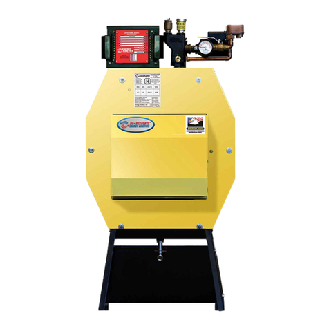
ENERGY KINETICS System 2000 Frontier User manual

ENERGY KINETICS

ENERGY KINETICS System 2000 Frontier User manual

ENERGY KINETICS EK3 Frontier Quick start guide

ENERGY KINETICS

ENERGY KINETICS EK3 Frontier Quick start guide

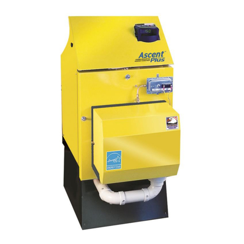
ENERGY KINETICS Ascent Combi Installation instructions

ENERGY KINETICS

ENERGY KINETICS Ascent Combi Installation instructions

ENERGY KINETICS System 2000 EK1 Frontier Service manual

ENERGY KINETICS

ENERGY KINETICS System 2000 EK1 Frontier Service manual

ENERGY KINETICS Resolute Boiler Supplement

ENERGY KINETICS

ENERGY KINETICS Resolute Boiler Supplement

ENERGY KINETICS Ascent Combi Installation instructions

ENERGY KINETICS

ENERGY KINETICS Ascent Combi Installation instructions

ENERGY KINETICS SYSTEM 2000 Accel CS Installation instructions

ENERGY KINETICS

ENERGY KINETICS SYSTEM 2000 Accel CS Installation instructions

ENERGY KINETICS System 2000 Service manual

ENERGY KINETICS

ENERGY KINETICS System 2000 Service manual

ENERGY KINETICS 90+RESOLUTE BOILER Installation instructions

ENERGY KINETICS

ENERGY KINETICS 90+RESOLUTE BOILER Installation instructions

ENERGY KINETICS System 2000 Supplement

ENERGY KINETICS

ENERGY KINETICS System 2000 Supplement

ENERGY KINETICS 90+RESOLUTE BOILER User manual

ENERGY KINETICS

ENERGY KINETICS 90+RESOLUTE BOILER User manual

ENERGY KINETICS EK2C Supplement

ENERGY KINETICS

ENERGY KINETICS EK2C Supplement

ENERGY KINETICS EK1 Frontier Service manual

ENERGY KINETICS

ENERGY KINETICS EK1 Frontier Service manual

ENERGY KINETICS Ascent Combi Service manual

ENERGY KINETICS

ENERGY KINETICS Ascent Combi Service manual

ENERGY KINETICS Resolute RT Installation instructions

ENERGY KINETICS

ENERGY KINETICS Resolute RT Installation instructions

ENERGY KINETICS 90+RESOLUTE BOILER Service manual
ENERGY KINETICS

ENERGY KINETICS 90+RESOLUTE BOILER Service manual

Popular Boiler manuals by other brands

Dunkirk Q90-200 Installation, operation & maintenance manual

Dunkirk

Dunkirk Q90-200 Installation, operation & maintenance manual

Burnham CHG150 Brochure & specs

Burnham

Burnham CHG150 Brochure & specs

Riello Array AR 800 Installation and operation manual

Riello

Riello Array AR 800 Installation and operation manual

Pierce Glas 24 Installation & operating instructions

Pierce

Pierce Glas 24 Installation & operating instructions

iMettos ENW-68DR instruction manual

iMettos

iMettos ENW-68DR instruction manual

STIEBEL ELTRON PSH-H 30 Trend Operation and installation instruction

STIEBEL ELTRON

STIEBEL ELTRON PSH-H 30 Trend Operation and installation instruction

Lennox GSB8-E installation instructions

Lennox

Lennox GSB8-E installation instructions

REMEHA Gas 210 ECO technical information

REMEHA

REMEHA Gas 210 ECO technical information

Riverside Hydronics WB 125A-IFC Installation & maintenance manual

Riverside Hydronics

Riverside Hydronics WB 125A-IFC Installation & maintenance manual

Ferroli PEGASUS F3 N 2S Instructions for use, installation and maintenance

Ferroli

Ferroli PEGASUS F3 N 2S Instructions for use, installation and maintenance

MASCOT HT 330 Installation and servicing instructions

MASCOT

MASCOT HT 330 Installation and servicing instructions

Radiant RSF 30 Installation and maintenance manual

Radiant

Radiant RSF 30 Installation and maintenance manual

Aztec Trianco G.C.No. EB 897 01 User & service installation instructions

Aztec

Aztec Trianco G.C.No. EB 897 01 User & service installation instructions

Gorenje GBFU 50 E/V6 manual

Gorenje

Gorenje GBFU 50 E/V6 manual

Baxi Solo HE A Series User operating instructions

Baxi

Baxi Solo HE A Series User operating instructions

Raypak Hydronic Space Heating 42-180 Specifications

Raypak

Raypak Hydronic Space Heating 42-180 Specifications

Beretta Junior Green C.S.I. installer and user manual

Beretta

Beretta Junior Green C.S.I. installer and user manual

IDEAL Vogue S15 Installation and servicing

IDEAL

IDEAL Vogue S15 Installation and servicing

manuals.online logo
manuals.online logoBrands
  • About & Mission
  • Contact us
  • Privacy Policy
  • Terms and Conditions

Copyright 2025 Manuals.Online. All Rights Reserved.