Twenty Ninth Edition – July 2005 7
CHIMNEY VENTING:
WARNING: Masonry chimneys must have a tile or metal liner. The liner must:
1) Extend above the masonry.
2) Have an insulating air gap, isolating the liner from the chimney, allowing for rapid heat-up and draft establishment.
3) Be sealed at each joint to prevent air infiltration and damage from condensation.
NOTICE: Inspect Chimney and Chimney base after initial three months of heating season.
The installation of a chimney cap is recommended. The base of the chimney must always have a drop leg below the
flue connector to allow scale and condensation to accumulate without blocking the flue pipe.
CAUTION: If drop leg is in excess of 12 inches deep, backfill with loose gravel or sand to obtain a maximum of 12-inch
depth. All clean out doors must be sealed to prevent cold air entry into chimney.
In retrofit installations, have chimney thoroughly cleaned. Carefully inspect chimney, base of chimney, and liner prior to
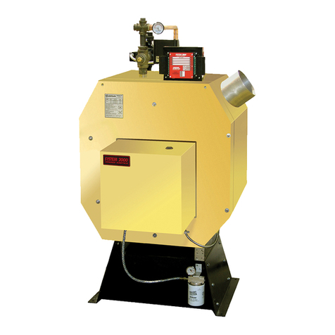
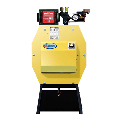
installation of System 2000 Boiler.
CAUTION: If liner is not sound, or if existing tile liner fails to contain intermittent condensation, or if excessive debris is
found at the base of the chimney, then it is recommended to install a properly sized metal liner approved for use with oil
heat appliances.
The metal liner diameter and length should be as recommended by the metal liner manufacturer. Corrugated metal
liners should be at least 5" diameter for EK1 and 6" diameter for EK2. Connection of a flexible metal liner directly to the flue
collar of the boiler is an acceptable connection method and is recommended. Energy Kinetics does not recommend use of
a base tee when a corrugated metal liner is installed. Alternatively, a flexible metal vent connector may be used between
the flue collar of the boiler and a flexible metal liner. Call Energy Kinetics for details on metal liners.
Chimney connectors should be positioned to create the shortest possible run of flue pipe to the chimney. The overall
horizontal length of flue piping should not exceed 15 feet. Long runs or low firing rates may require insulated flue pipe such
as L-Vent or All-Fuels to keep the temperature at base of chimney adequate for draft and to prevent corrosion of piping and
connectors.
Because the System 2000 boiler uses a power burner, the flue pipe may experience some positive pressure on start
up. Energy Kinetics recommends that all pipe joints be sealed with high temperature silicone sealant to ensure passage of
all combustion products to the chimney.
Normally, pitch horizontal flue pipe up toward chimney approximately ¼” per foot. For existing installations, it is
permissible for the flue connection of the boiler to be higher than the chimney thimble, provided adequate draft is
established.
If a minimum of -0.02” w.c. draft overfire is not present after sufficient burner run time to heat up the chimney, there is a
problem that will need to be corrected. Call Energy Kinetics for help resolving draft problems. Under normal
circumstances, there is NO need for a DRAFT REGULATOR and one should not be installed. Call Energy Kinetics with
questions about flue pipe sizing.
WARNING: No solid fuel appliance or fireplace should be installed in a flue common with this heating appliance. The
flue gas exit of the venting system must be at least three (3) feet above the point at which it passes through the roof and at
least two (2) feet higher than any portion of a building within 10 feet horizontally of its location.
L-Vent Chimney:
SYSTEM 2000 Boilers typically have flue gas temperatures between 350F and 450F during normal operation. Due to
the low flue gas temperatures, L-Vent chimney pipe is suitable for use with SYSTEM 2000 Boilers. L-Vent chimney pipe
may require smaller chase dimensions than other chimney pipe materials and should be considered for new installations
with SYSTEM 2000 Boilers. Call Energy Kinetics for help locating sources of L-Vent.
1. L-Vent must be U.L. Listed to U.L. 641.
2. L-Vent to be installed in accordance with the vent manufacturer’s instructions.
3. System 2000 and L-Vent must be installed in strict compliance with all State and Local Codes and with the regulations of
the authorities having jurisdiction, which may differ from and which take precedence over these instructions or the vent
manufacturer’s instructions.
Sidewall Venting:
1. System 2000 Boilers may be installed with Energy Kinetics' sidewall vent kit in accordance with kit instructions.
2. WARNING: Sidewall vent systems must have outside air connected to the air box and both air box air intake and vent
hood must be located on the same side of the structure.
3. NOTICE: The sidewall vent inducer should be located above the boiler flue outlet, preferably a minimum of four feet
vertical distance, which will provide some natural draft to the boiler (and cooling of the burner) in case of a power failure.
4. When installing a sidewall venting system from another manufacturer, ensure that the manufacturer’s instructions are
followed. Vent manufacturer should confirm that the equipment is suitable for use with System 2000.
5. Set the draft over fire through the puff switch opening between -.10" to -.12" w.c. with the burner running, after allowing
time for sufficient warm-up. Check/adjust CO2. Re-check the draft over fire and adjust draft if necessary.
6. To provide power to the sidewall vent, install the plug-in relay supplied with the sidewall vent kit into the junction box
relay board and set the Digital Manager Option Switch #2 to the “ON” (down) position. This enables the “Inducer” light
and allows the Digital Manager to control the inducer. Refer to Digital Manager section for option switch settings and
inducer timing details.


