manuals.online logo
Brands
  1. Home
  2. •
  3. Brands
  4. •
  5. ENERMAX
  6. •
  7. Computer Accessories
  8. •
  9. ENERMAX Leonids ECA-LN30 Series User manual

ENERMAX Leonids ECA-LN30 Series User manual

Other ENERMAX Computer Accessories manuals

ENERMAX CLIPEUS User manual

ENERMAX

ENERMAX CLIPEUS User manual

ENERMAX Ostrog ECA3380AS Series User manual

ENERMAX

ENERMAX Ostrog ECA3380AS Series User manual

ENERMAX LED CASE FAN User manual

ENERMAX

ENERMAX LED CASE FAN User manual

ENERMAX BLACK User manual

ENERMAX

ENERMAX BLACK User manual

ENERMAX Coenus ECA3290B User manual

ENERMAX

ENERMAX Coenus ECA3290B User manual

ENERMAX CLIPEUS User manual

ENERMAX

ENERMAX CLIPEUS User manual

ENERMAX EQUILENCE ECA3510 User manual

ENERMAX

ENERMAX EQUILENCE ECA3510 User manual

ENERMAX Staray ECA3170 User manual

ENERMAX

ENERMAX Staray ECA3170 User manual

ENERMAX HOPLITE User manual

ENERMAX

ENERMAX HOPLITE User manual

ENERMAX Saberay ECA3500 User manual

ENERMAX

ENERMAX Saberay ECA3500 User manual

ENERMAX LUXURAY ECA3190-B User manual

ENERMAX

ENERMAX LUXURAY ECA3190-B User manual

ENERMAX APOLLISH VEGAS User manual

ENERMAX

ENERMAX APOLLISH VEGAS User manual

ENERMAX MAGMA User manual

ENERMAX

ENERMAX MAGMA User manual

Popular Computer Accessories manuals by other brands

Netstor NA255A user manual

Netstor

Netstor NA255A user manual

perixx PERIDUO-610 user manual

perixx

perixx PERIDUO-610 user manual

Cherry PURE JD-0100 operating manual

Cherry

Cherry PURE JD-0100 operating manual

Cool-Icam DICK II user manual

Cool-Icam

Cool-Icam DICK II user manual

Motorola ATRIX user guide

Motorola

Motorola ATRIX user guide

HP USB Media Docking Station specification

HP

HP USB Media Docking Station specification

Cherry B.UNLIMITED 3.0 user manual

Cherry

Cherry B.UNLIMITED 3.0 user manual

Bartec TC 7 Series user guide

Bartec

Bartec TC 7 Series user guide

Philips SPC3540 Specifications

Philips

Philips SPC3540 Specifications

Logitech mk220 user manual

Logitech

Logitech mk220 user manual

Vivo MOUNT-KB05-4DW instruction manual

Vivo

Vivo MOUNT-KB05-4DW instruction manual

SilverStone LC02 manual

SilverStone

SilverStone LC02 manual

Flexispot ML2B installation guide

Flexispot

Flexispot ML2B installation guide

Hamlet UNIVERSAL COVER 101 KBT2 user manual

Hamlet

Hamlet UNIVERSAL COVER 101 KBT2 user manual

Adam Equipment RS-485 manual 

Adam Equipment

Adam Equipment RS-485 manual 

Sven Base 305 сombo instructions

Sven

Sven Base 305 сombo instructions

Hama 108310 Operating	 instruction

Hama

Hama 108310 Operating instruction

SpeechWare FlexyMike FMK03 user manual

SpeechWare

SpeechWare FlexyMike FMK03 user manual

manuals.online logo
manuals.online logoBrands
  • About & Mission
  • Contact us
  • Privacy Policy
  • Terms and Conditions

Copyright 2025 Manuals.Online. All Rights Reserved.

User’s Manual
Handbuch
Instrukcja obsługi
ユーザ マニュアル
使用手冊
English
Deutsch
Polski
日本語
繁中
ECA-LN30 Series
Chapter 1 :
•Product Overview •Produkteinführung •Opis produktu
•製品の説明       •產品槪觀 
1.1 Product View
Produktskizze
Rozkład elementów
製品ビュー
產品外觀
Le Front Right
Rear
Top
Power
Headphone
USB Ports
1.2 Specs
Technische Daten
Dane techniczne
スペック
產品規格
*Product specifications are subject to change without notice.
*Options vary by countries or regions.
*For detailed information please visit our website at www.enermax.com
Chapter 2 :
•Installaon Guide •Montageanleitung •Instrukcja montażu
•取り付けの説明     •組裝說明
2.1 How to Remove Both Side Panels
Enernen der Seitenwände
Demontaż panelów bocznych
両サイドパネルの取り外し
兩側側板拆卸
A
B
2.2 How to Install the Motherboard
So installieren Sie das Motherboard
Jak zamontować płytę główną
マザーボードの取り付け方法
安裝主機板
2.3 How to Install Power Supply
Netzteileinbau
Jak zainstalować zasilacz
komputerowy
電源取り付け方法
安裝電源供應器
Reset
Microphone
ECA-LN30 series
427mm x 205mm x 475 mm
0.6mm SPCC
ATX, Micro ATX, Mini ITX
USB 3.0 x 2, HD Audio
2
5 (2 x converted from 3.5” Tray)
7
2 x 140mm or 3 x 120mm
2 x 140mm or 2 x 120mm
1 x 120mm
360mm / 280mm / 240mm radiator
280mm / 240mm radiator
120mm radiator
Standard ATX Type
Model Number
Dimensions (Case)
Material
M/B Type
I/O
Expansion Slots
PSU Support
3.5”
2.5”
Front
Top
Rear
Front
Top
Rear
1
2
Fan Slots
©2019 ENERMAX TECHNOLOGY CORPORATION. All right reserved.
Specifications are subject to change without prior notice. Some trademarks may be claimed as the property of others.
Drive Bays
2
2
3
2
1
1
1
2.4 How to Install Internal 2.5“ & 3.5“ Device
Installaon von internen 2,5“- und 3,5“-Laufwerken
Instalacja wewnętrznych napędów 2.5“/3.5“
内部2.5インチと3.5インチデバイスの取り付け
安裝隱藏之3.5”/2.5”裝置
A
B
B
1
1
1
2
2.4.1
2.4.2
Liquid Cooling
1
375mm
235mm
Remove the HDD cage to create extra space for cable management
2
2
A
2.5”
HDD/SSD
2.5”
HDD/SSD
2.5”
HDD/SSD
2.5”
HDD/SSD
2.5”
HDD/SSD
Move the HDD cage forward to create extra space for cable management
2
1
1
AB
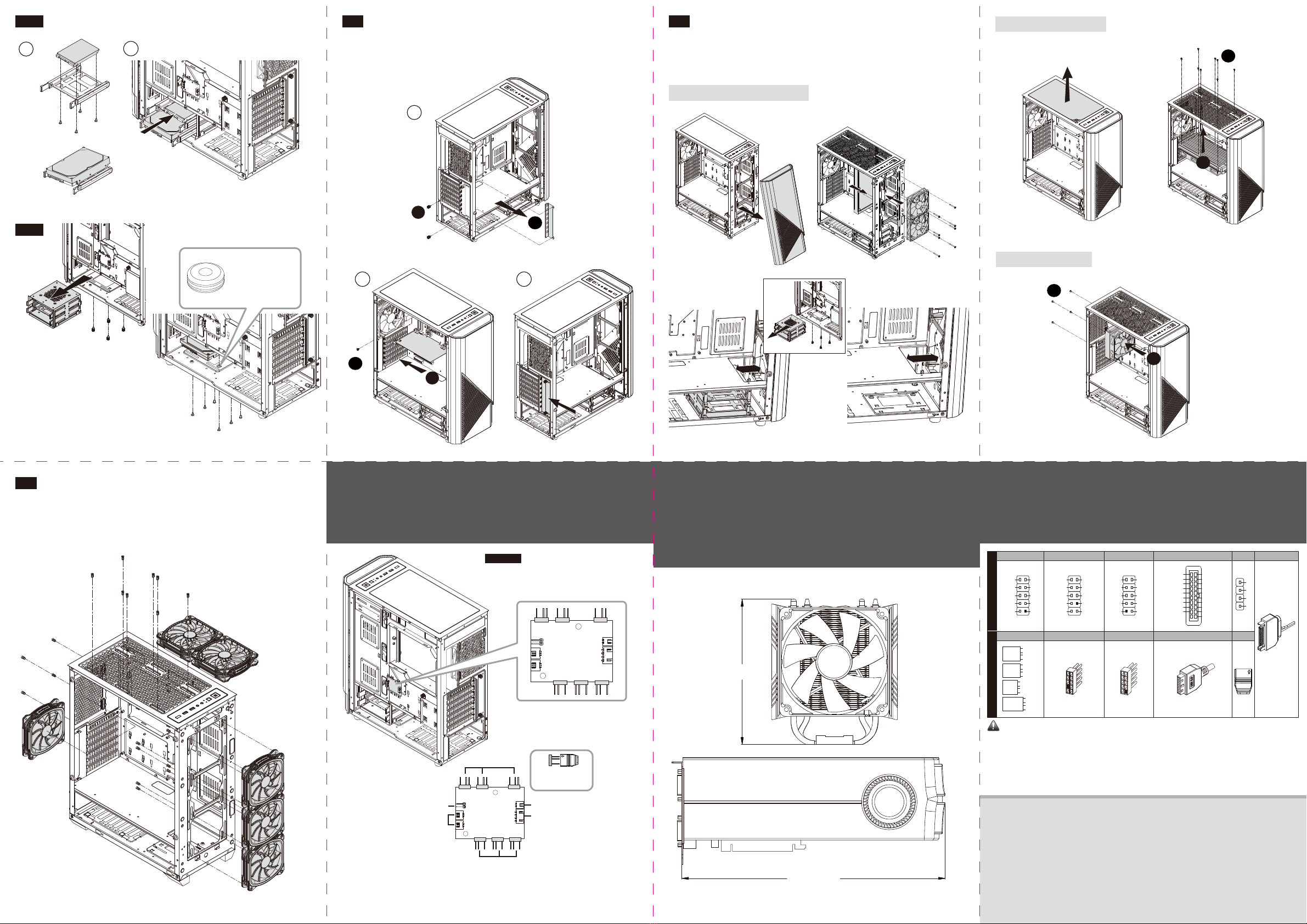
2.5 How to Install Add-on Cards
Installaon von Erweiterungskarten
Instalacja kart rozszerzenia
アドオンカードの取り付け
安裝擴充卡
Chapter 4 :
•Suggested Height of CPU Cooler and Length of VGA card
•Empfohlene Höhe des CPU-Kühlers und Länge der Grafikkarte
•Polecana wysokokość coolerów CPU oraz długość kart graficznych
•CPUクーラーの高さとVGAカードの長さについて  
•CPU cooler高度及顯示卡長度建議
If you have any question or need support, please contact your reseller or nearest
ENERMAX subsidiary/agent or ENERMAX headquarter service center.
Falls Sie Fragen haben oder Support benötigen, wenden Sie sich bitte an Ihren Händler, Ihre nächste
ENERMAX-Niederlassung, deren Agenten oder an das ENERMAX Headquarter Service Center!
Schnelle Hilfe bei allen Fragen zu ENERMAX-Produkten erhalten Sie auch online unter
www.enermax.de/warranty.
W przypadku pytań lub potrzeby skorzystania z serwisu należy skontaktować się ze sprzedawcą ENERMAX
albo z siedzibą główną centrum serwisowego ENERMAX. Bezpośrednią pomóc techniczną można uzyskać
również online na www.enermax.pl/warranty.
ご質問やサポートが必要な場合、ご購入元またはENERMAX販売代理店、当社サポートにお問い合わせください。
如果您有任何問題或需要支援,敬請聯絡您的產品經銷商,或是保銳科技總公司服務中心:
[email protected]
Chapter 5 :
•Cable Connecon Descripon
•Anschlussübersichtg
•Przewody w obudowie
•ケーブル接続の説明 
•線材安裝說明
Noce:
•On some motherboards, the connectors might not be exactly the same as the drawings above, please check with
your motherboard manual before installing
•Bei einigen Mainboards ist der Stecker unter Umständen nicht identisch mit dem auf der Zeichnung oben.
•Wtyczki niektórych płyt głównych mogą odróżniać się od tych na rysunku powyżej. Proszę również przeczytać
instrukcję obsługi płyty głównej przed instalacją.
•マザーボードによってはコネクタ類の形状が上の図面と異なる場合がございます。詳しくはマザーボードの取扱説明書を
ご参照ください。
•圖面所示之線材可能與使用之主機板不儘相同,安裝前請參考主機板廠所提供之說明書。
Apr. 2019
2.6 How to Install the Radiators
Installaon eines Radiators
Instalacja radiatora
ラジエーターの取付方法
安裝水冷散熱器
2.7 How to Install System Fans
Installaon der Systemlüfer
Instalacja wentylatorów systemu
ケースファンの取り付け
機箱風扇安裝
1
1
2
2
2
2
Front 360/280/240mm radiator
2 x 140mm / 2 x 120mm
1 x 120mm
2 x 140mm / 3 x 120mm
2.4.3
2.4.4
A
BC
2.5”
HDD/SSD
3.5” HDD
Top 280/240mm radiator
Rear 120mm radiator
63.7mm
38.8mm
*Remove the HDD cage to create extra space for thicker radiator installaon
Chapter 3 :
•RGB Control Hub •RGB-Lüersteuerung
•Panel regulacji RGB •RGB ドハブ
•RGB集線器
CAUTION:
ARGB Hub Max. Current: 5A
Rated Current of Pre-installed Fan: 0.68 A (pc)
Rated Current of Pre-installed LED strip: 0.48 A (pc)
*Opons vary by countries or regions
ARGB Header
ARGB Header
**Reset header
Pre-installed LED
strips
M/B Sync Cable
Power source
Please follow the
instrucon while
connecng the port.
5V
D
–
G
157.6mm
375mm
POWER
SW
PWR
GND
H.D.D.
LED
ID ELED+
ID ELED-
RESET
SW
Ground
Reset
POW LED-
POW LED+
PLED-
PLED+
ID ELED+
ID ELED-
PLED+
PLED-
Ground
Reset
PWR
GND
NC No Pin
MIC2_L
MIC2_R
HP_R
Jack_Sense
HP_L
AGND
PRESENSE#
MIC2_JD
No Pin
HP_HD
USB +5V
USB_P-
USB_P+
GND
No Pin
USB +5V
USB_P-
USB_P+
GND
NC
IntA_P2_D+
IntA_P2_D-
GND
IntA_P2_SSTX+
IntA_P2_SSTX-
GND
IntA_P2_SSRX+
IntA_P2_SSRX-
Vbus
ID
IntA_P2_D+
IntA_P2_D-
GND
IntA_P2_SSTX+
IntA_P2_SSTX-
GND
IntA_P2_SSRX+
IntA_P2_SSRX-
Vbus
Panel Connector
Panel Connector
USB 3.0 Connector
USB 3.0 Connector
USB 2.0 Connector
USB 2.0 Connector
SYNC
SYNC
*Please connect to PSU.
SATA
MotherboardCable
HD Audio Connector
HD Audio Connector
5V
D
-
G
5V
D
-
G
(Oponal)
*You could find the
HDD rubber pads
in the accessory pack.
**Convert Reset buon to RGB control buon
Step 1: Connect the case’s Reset cable to the Reset header on the ARGB hub.
Step 2: The reset funcon will be disabled; the reset buon will become RGB control buon.
Users may use the buon to select 13x pre-set lighng modes.
Step 3: User may switch the RGB sync controlled by M/B or case through long pressing the
RGB control buon for 2~3 seconds.