manuals.online logo
Brands
  1. Home
  2. •
  3. Brands
  4. •
  5. EnerSys
  6. •
  7. Camera Accessories
  8. •
  9. EnerSys Oerlikon Water Less User manual

EnerSys Oerlikon Water Less User manual

Instructions for use Oerlikon®Water Less®ENGLISH
1. Commissioning filled and charged batteries
For commissioning of unfilled batteries see separate
instructions! The battery should be inspected to ensure it
is in perfect physical condition. The charger cables must
be connected to ensure a good contact, taking care that the
polarity is correct. Otherwise battery, vehicle or charger could
be damaged.
For the assembly of harness cables or in case of the replacement
of a connector the following torque must be applied:
M10 perfect connector 25 ± 2Nm
In case the interval between delivery (see manufacturing date
on type plate) and commissioning is longer than 8 weeks or the
electrolyte level sensor is indicating low electrolyte level (see
table, section 3.1.1), the electrolyte level has to be checked. If
the battery is equipped with a single point water topping up
system (optional), for the removal of the BFS plugs only the
appropriate tool must be used. Otherwise the floats of plugs
may be permanently damaged, which can cause overflow
of the cells. If the electrolyte level is below the top of the
separator, it must first be topped up to this height with
purified water (IEC 62877-1: 2016). The battery is then charged
as in section 2.2.
The electrolyte should be topped up to the specified level with
purified water. Oerlikon Water Less®batteries are fitted with
an electrolyte level indicator.
2. Operation
EN 62485-3 “Traction batteries for industrial trucks” is the
standard which applies to the operation traction batteries in
industrial trucks.
2.1 Discharging
Be sure that all ventilation holes are not sealed or covered.
Electrical connections (e.g. plugs) must only be made or
broken in the open circuit condition. To achieve the optimum
life for the battery, operating discharges of more than 80% of
the rated capacity should be avoided (deep discharge). This
corresponds to an electrolyte specific gravity of 1.14 kg/l at
30°C at the end of the discharge. Discharged batteries must be
recharged immediately and must not be left discharged. This
also applies to partially discharged batteries.
2.2 Charging
Only direct current must be used for charging.
All charging procedures in accordance with EN 41773-1
and EN 41774 are permitted. Connect the battery assigned
to a charger, suitable for the size of battery, in order to
avoid overloading of the electric cables and contacts,
unacceptable gassing and the escape of electrolyte from
the cells. In the gassing stage the current limits given in
EN 62485-3 must not be exceeded. If the charger was not
purchased together with the battery, it is best to have its
suitability checked by the manufacturers service department.
When charging, proper provision must be made for venting of
the charging gases. Doors, battery container lids and covers
of battery compartments must be opened or removed. During
the charge, the battery must be removed from the closed
battery compartment on the truck. The ventilation must
comply to EN 62485-3 standard. The vent plugs should stay
on the cells and remain closed. With the charger switched off,
connect up the battery, ensuring that the polarity is correct
(positive to positive, negative to negative). Now switch on the
charger. When charging, the temperature of the electrolyte
rises by about 10°C, so charging should only begin if the
electrolyte temperature is below 45°C.
SAFETY PRECAUTIONS
• Pay attention to the operation instruction and
fix them close to the battery.
• Work on batteries to be carried out by skilled
personnel only!
• Use protective glasses and clothes when
working on batteries. Pay attention to the
accident prevention rules as well as EN 62485-3
and EN 50110-1.
• No smoking!
• Do not expose batteries to naked flames,
glowing embers or sparks, as it may cause the
battery to explode.
• Acid splashes in the eyes or on the skin must
be washed with water. In case of accident
consult a doctor immediately!
• Clothing contaminated by acid should be
washed in water.
• Risk of explosion and fire, avoid short circuits!
• Caution: Metal parts of the battery are always
live. Do not place tools or other metal objects
on the battery!
• Electrolyte is highly corrosive.
• Batteries and cells are heavy.
• Ensure secure installation! Use only suitable
handling equipment e.g. lifting gear in
accordance with VDI 3616.
• Dangerous electrical voltage!
• Pay attention to the hazards that can be
caused by batteries.
Rating Data
1. Nominal capacity C5: See type plate
2. Nominal voltage : 2.0 V x No of cells
3. Discharge current : C5/5h
4. Nominal S.G. of electrolyte*
Type PzM / PzMB : 1.29 kg/l
5. Rated temperature : 30°C
6. Nominal electrolyte level : up to electrolyte level mark ”max.”
* Will be reached within the first 10 cycles.
Traction batteries with positive tubular plates type PzM / PzMB
Ignoring the operating instructions, and repair with non-original parts will render the warranty void.
All failures, malfunctions and fault codes of the battery, the charger or any other accessories, must be notified to EnerSys®
service immediately.
The electrolyte temperature of batteries should be at least
+10°C before charging otherwise a full charge will not be
achieved. A charge is finished when the specific gravity of the
electrolyte and the battery voltage have remained constant for
2 hours.
2.3 Equalising charge
Equalising charges are used to safeguard the life of the
battery and to maintain its capacity. They are necessary after
deep discharges, repeated incomplete recharges and charges
to an IU characteristic curve. Equalising charges are carried
out following normal charging. The charging current must
not exceed 5A/100Ah of rated capacity (see section 2.2).
Pay attention to the temperature!
2.4 Temperature
An electrolyte temperature of 30°C is specified as the rated
temperature. Higher temperatures shorten the life of the
battery, lower temperatures reduce the capacity available.
55°C is the upper temperature limit and is not acceptable as
an operating temperature.
2.5 Electrolyte
The rated specific gravity (S. G.) of the electrolyte is related to
a temperature of 30°C and the nominal electrolyte level in the
cell in fully charged condition.
Higher temperatures reduce the specified gravity of the
electrolyte, lower temperatures increase it. The temperature
correction factor is -0.0007kg/l per °C, e.g. an electrolyte
specific gravity of 1.28kg/l at 45°C corresponds to an S.G. of
1.29kg/l at 30°C. The electrolyte must conform to the purity
regulations in IEC 62877-2: 2016.
3. Maintenance
3.1 Daily
Charge the battery after every discharge. Oerlikon Water
Less®with electrolyte circulation: at the end of charge the
electrolyte level sensor should be checked (see table 3.1.1)
and if necessary topped up to the specified level with purified
water (according IEC 62877-1: 2016).
NO WATERING IN THE FIRST 10 CYCLES.
3.1.1 Filling level sensors
The LED of the electrolyte level sensor should be observed
daily.
ELECTROLYTE LEVEL INDICATOR
TYPE (2 - 3)... PzMB
white housing
Green –electrolyte level is OK
No indication –water topping up should
be carried out
TYPE (2 - 10)... PzM and (4 - 11)... PzMB
blue housing
Green flashing –electrolyte level is OK
Green/red flashing –safety cycle limit
countdown
Red flashing –water topping up should be
carried out
Do not top up the cells even when electrolyte level sensor
shows a red blinking LED during first 10 cycles.
The electrolyte level checking has to be performed after low
level detection of the sensor or after water topping up interval
(see "Water refilling system") Check the electrolyte level
(visual inspection by opening the vent plug or by the position
of the float indicator of the Aquamatic plug) and top-up with
demineralised water at the end of the charge. Since the
display always refers to a selected reference cell, please also
pay attention to the additional instructions under section 3.3.
3.2 Weekly
Visual inspection after recharging for signs of dirt and
mechanical damage to all component parts of the battery, pay
particular attention to the battery charging plugs and cables.
By special applications with charge with a IU characteristic
curve an equalising charge must be carried out (see sections
2.3 and 7.).
3.3 Monthly
At the end of the charge the voltages of all cells should be
measured with the charger switched on, and recorded.
After charging has been completed, the electrolyte density,
electrolyte temperature as well as the filling level (when filling
level sensors are used) of all cells are to be measured and
recorded. If significant changes from earlier measurements
or differences between the cells are found further testing and
maintenance by the service department should be requested.
This should be done following a complete charge and
minimum of 2 hours rest time.
Measure and record:
• totalvoltage
• voltagepercell
• ifthevoltagereadingsareirregular,alsocheck
the S.G. of each cell
(see section 7.)
3.4 Quarterly
Follow section 7.
3.5 Annually
In accordance with EN 1175-1 at least once per year, the
insulation resistance of the truck and the battery must be
checked by an electrical specialist. The tests on the insulation
resistance of the battery must be conducted in accordance
with EN 1987-1. The insulation resistance of the battery
thus determined must not be below a value of 50Ωper volt
of nominal voltage, in compliance with EN 62485-3. For
batteries up to 20V nominal voltage the minimum value is 1000Ω.
Proceed to the quarterly maintenance, including the
measurement of electrolyte S.G. at the end of charge.
For batteries equipped with optional electrolyte circulation
system, the filter of the air pump has to be checked during the
annual maintenance and eventually to be cleaned or replaced.
Earlier replacement of the filter is necessary if for undefined
reasons (no leaks in the air pipes) the defect signal of the
electrolyte circulation system on the charger or on the battery
(on DC air pump or remote signal) is illuminated. During the
annual maintenance, check the correct operation of the air
pump.
4. Care of the battery
The battery should always be kept clean and dry to prevent
tracking currents. Cleaning must be done in accordance with
the ZVEI code of practice “The Cleaning of Vehicle Traction
batteries”.
Any liquid in the battery tray must be extracted and disposed
of in the prescribed manner. Damage to the insulation of the
tray should be repaired after cleaning, to ensure that the
insulation value complies with EN 62485-3 and to prevent tray
corrosion. If it is necessary to remove cells, it is best to call in
our service department for this.
Never use (apply) mineral grease on the battery, the
sealing material of the terminal is incompatible and it can
be permanently damaged. If it's necessary, use (apply) the
silicone grease with TPFE.
5. Storage
If batteries are taken out of service for a lengthy period, they
should be stored in the fully charged condition in a dry, frost-
free room. To ensure the battery is always ready for use a
choice of charging methods can be made:
1. a monthly equalising charge as in section 2.3, or
2. float charging at a charging voltage of 2.27V x the number
of cells.
The storage time should be taken into account when
considering the life of the battery.
6. Malfunctions
If malfunctions are found on the battery or the charger our
service department should be called in without delay. The
measurements taken in section 3.3 will facilitate fault finding
and their elimination.
A service contract with us will make it easier to detect and
correct faults in good time.
1. Application
The water refilling system is used to automatically maintain
the nominal electrolyte levels.
The charging gasses escape through the vent on each cell.
NO WATERING IN THE FIRST 10 CYCLES.
2. Function
A valve and a float together control the topping up process
and maintain the correct water level in each cell. The valve
allows the flow of water into each cell and the float closes the
valve when the correct water level has been reached.
For fault-free operation of the water refilling system, please
note the instructions below:
2.1 Manual or automatic connection
The battery should be topped up shortly before completion
of a full charge, as at this point the battery has reached a
defined operational state resulting in satisfactory electrolyte
circulation. Filling takes place when the connector (7) from the
tank is connected to the coupling (6) on the battery.
Manual or automatic coupling has to be done in the intervals
according to section 7.
2.2 Filling time
Filling time depends on the utilisation rate and the
corresponding battery temperature. Generally speaking, the
top up process takes a few minutes and can vary according to
the battery range; after this, if manual filling is being used, the
water supply to the battery should be turned off.
2.3 Working pressure
The water refilling system should be installed in such a way
that a water pressure of 0.2 to 0.6 bar is obtained (with at least
2m height difference between the upper edge of the battery
and the lower edge of the tank). Any deviation from this
means that the system will not function properly.
2.4 Purity
The topping up water must be purified. The water used to
refill the batteries must have a conductance of not more
than 30µS/cm. The tank and pipes must be cleaned before
operating the system.
2.5 Pipe system on the battery
The pipe system to the individual battery cells must follow
the battery’s electrical circuit. This reduces the risk of current
leakage in the presence of electrolytic gas causing an
explosion (EN 62485-3). A maximum of 18 cells may be
connected in a series.
The system should not be modified in any way.
2.6 Working temperature
In winter, batteries fitted with Aquamatic should only be
charged or refilled in a room temperature above 0°C.
2.7 Flow control
A flow indicator built into the water supply pipe to the battery
monitors the filling process. During filling the water flow
causes the built-in disc in the flow indicator to turn. When all
the plugs are closed the disc stops, indicating that the filling
process is complete.
7. Water topping up interval
Optional accessories
Water refilling system
1. tank
2. outflow connector with ball valve
3. plug with magnetic valve
4. plug with ball valve
5. flow control
6. coupling
7. connector
8. battery charger
9. charger main switch
1
2
4
5
3
7
6
9
8
PzM Variant & Conditions Water topping up intervals*
1 shift operation 3 shift operation**
4 Weeks PzM/PzMB plus 50Hz 20 Cycles (4 weeks) 20 Cycles (2 weeks)
8 Weeks PzM/PzMB plus HF 40 Cycles (8 weeks) 40 Cycles (5 weeks)
13 Weeks PzM/PzMB plus EC*** & HF 65 Cycles (13 weeks) 65 Cycles (8 weeks)
80% DOD, 5 operating days per week, and average battery temperatures of 20°C
* +/- 1 week in the most common applications at 20°C
** this number of cycles can be reduced if operating 3 shift and with high battery temperatures!
*** Electrolyte Circulation
1. Application
The electrolyte circulation system is based on the principle
of pumping air into the individual battery cells. This system
prevents electrolyte stratification and the battery charge
is optimised using a charge factor of 1.07. The electrolyte
circulation is particularly beneficial for heavy duty use, short
charge times, boost or opportunity charging and in high
ambient temperatures.
2. Function
The electrolyte circulation consists of a pipe system fitted
in the cells. The Aeromatic diaphragm pump is fitted in the
charger or separately mounted on the battery or vehicle. This
diaphragm pump sends a low rate airflow into each cell which
creates a circulating air stream inside the cell box.
The air stream is continuous or pulsed depending on the
battery voltage and pump type. The air supply is adjusted in
accordance to the number of cells in the battery.
The pipe system to the individual battery cells must follow
the existing electrical circuit. This reduces the risk of current
leakage in the presence of electrolytic gas causing an
explosion (EN 62485-3).
2.1 Use with separate pipe system
Air is supplied when the charger pipe system is connected to
the battery pipe system (with blue ring).
2.2 Use with automatic connection of the pipe system
Connecting the charge plug with integrated air supply
automatically supplies air to the battery.
2.3 Maintenance of air filter
Depending on the working conditions, the pump air filter
should be changed at least once a year. In work areas with
high levels of air-pollution, the filter should be checked and
replaced more frequently.
2.4 Repair and maintenance
The system must be checked for leakage. The charger will
display an error message to indicate leakage. Sometimes
in the case of leakage the characteristic charging curve is
switched over to the characteristic standard curve (without
electrolyte circulation).
Faulty parts and faulty pipe sections must be replaced. Only
original spare parts may be used, as these are designed for
the pump air supply and will ensure correct functioning of
the pump.
Electrolyte circulation system
The Wi-iQ is the electronic device that communicates
wirelessly to download the battery key information for better
diagnostics & service. The device is fitted to a main DC cable
on the battery to monitor and record data of current, voltage,
temperature and electrolyte level (via optional external
sensor). The LEDs on the Wi-iQ provide real time status of
battery’s condition. The information is transferred to the
PC or to smartphone via USB or by wireless communication.
1. Operation
The Wi-iQ is suitable for use on all battery technologies.
Voltage range is 24V – 120V.
The device records global data during the life of the battery. It
will store data for 2555 cycles (complete history stored by PC).
The data can be analysed by Wi-iQ Report or E-Connect app,
depending on Wi-iQ version fitted to the battery.
2. Clear visibility
Selecting the Wi-iQ Report or E-Connect app will provide
information on the condition of your battery and any actions
that are necessary. Wi-iQ Report or E-Connect app will quickly
enable you to get a handle on your battery fleet charging
& discharging characteristics. With information by battery
family (truck type) you can see depth of discharge charts,
cycles, charging and much more.
See the Wi-iQ User Manual for further details.
Wi-iQ
®
Back to the manufacturer!
Batteries with this sign must be recycled.
Batteries which are not returned for the recycling process must be disposed of as hazardous waste!
When using motive power batteries and chargers, the operator must comply with the current standards, laws,
rules, and regulations in force in the country of use!
© 2021 EnerSys. All rights reserved. Trademarks and logos are the property of EnerSys and its affiliates unless
otherwise noted. Subject to technical modification without any prior notice. E.&O.E.
www.enersys.com
Publication no: EMEA-EN-MI-OLK-WL-0321

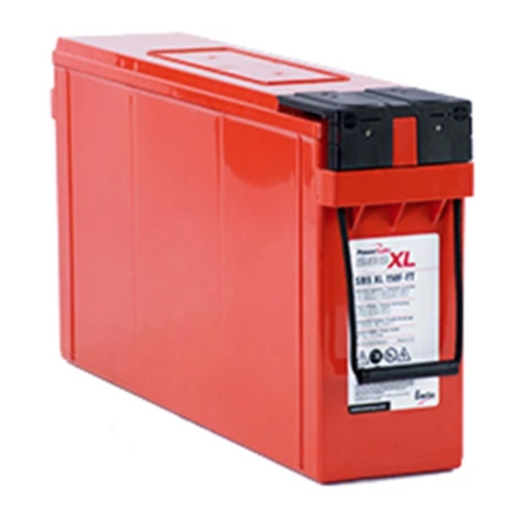
Other EnerSys Camera Accessories manuals

EnerSys Nexsys 12NXS26 Troubleshooting guide

EnerSys

EnerSys Nexsys 12NXS26 Troubleshooting guide

EnerSys PowerSafe OPzV Series User manual

EnerSys

EnerSys PowerSafe OPzV Series User manual

EnerSys RL Series User manual

EnerSys

EnerSys RL Series User manual

EnerSys Oerlikon Evolution User manual

EnerSys

EnerSys Oerlikon Evolution User manual

EnerSys PowerSafe SBS XL User manual

EnerSys

EnerSys PowerSafe SBS XL User manual

EnerSys PowerSafe SBS XC+ User manual

EnerSys

EnerSys PowerSafe SBS XC+ User manual

EnerSys TP Series Troubleshooting guide

EnerSys

EnerSys TP Series Troubleshooting guide

EnerSys Nexsys 12NXS26 User manual

EnerSys

EnerSys Nexsys 12NXS26 User manual

EnerSys ODYSSEY EXTREME PC310 User manual

EnerSys

EnerSys ODYSSEY EXTREME PC310 User manual

EnerSys PowerSafe mP Series Setup guide

EnerSys

EnerSys PowerSafe mP Series Setup guide

EnerSys SuperSafe SBS EON Series User manual

EnerSys

EnerSys SuperSafe SBS EON Series User manual

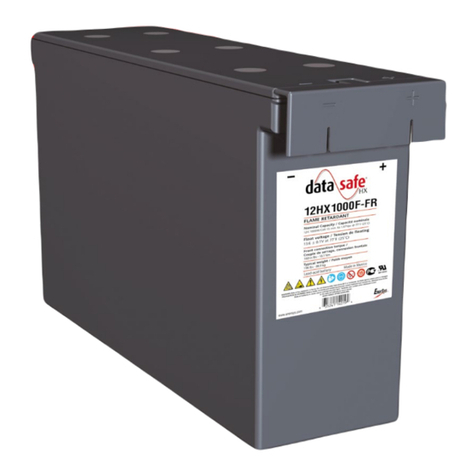
EnerSys DataSafe 12HX1000F-FR Manual

EnerSys

EnerSys DataSafe 12HX1000F-FR Manual

EnerSys Hawker Perfect Plus User manual

EnerSys

EnerSys Hawker Perfect Plus User manual

EnerSys NexSys CORE Series Troubleshooting guide

EnerSys

EnerSys NexSys CORE Series Troubleshooting guide

EnerSys HAWKER 9750F0530 User manual

EnerSys

EnerSys HAWKER 9750F0530 User manual

EnerSys PowerSafe RL Series User manual

EnerSys

EnerSys PowerSafe RL Series User manual

EnerSys Oerlikon Perfect Plus User manual

EnerSys

EnerSys Oerlikon Perfect Plus User manual

EnerSys DataSafe HX+ User manual

EnerSys

EnerSys DataSafe HX+ User manual

EnerSys PowerSafe SBS XC Series User manual

EnerSys

EnerSys PowerSafe SBS XC Series User manual

EnerSys OutBack POWER NorthStar NSB BLUE+ Series User manual

EnerSys

EnerSys OutBack POWER NorthStar NSB BLUE+ Series User manual

EnerSys DataSafe 16HX FT Series Manual

EnerSys

EnerSys DataSafe 16HX FT Series Manual

EnerSys DataSafe HX General instructions

EnerSys

EnerSys DataSafe HX General instructions

EnerSys ZeMa200P18 User manual

EnerSys

EnerSys ZeMa200P18 User manual

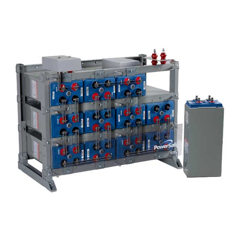
EnerSys PowerSafe SBS Series User manual

EnerSys

EnerSys PowerSafe SBS Series User manual

Popular Camera Accessories manuals by other brands

Cactus PT-04 user manual

Cactus

Cactus PT-04 user manual

Philips PowerLife 6LR61P1B brochure

Philips

Philips PowerLife 6LR61P1B brochure

PhaseOne XF V-Grip quick guide

PhaseOne

PhaseOne XF V-Grip quick guide

dji Ronin user manual

dji

dji Ronin user manual

Norman P808-1200 instruction manual

Norman

Norman P808-1200 instruction manual

Nauticam 16347 instruction manual

Nauticam

Nauticam 16347 instruction manual

D-Link DCS-60 user manual

D-Link

D-Link DCS-60 user manual

Neato Robotics Botvac manual

Neato Robotics

Neato Robotics Botvac manual

Sideline Power High Riser Lite Setup instructions

Sideline Power

Sideline Power High Riser Lite Setup instructions

Sachtler Video 18 SB manual

Sachtler

Sachtler Video 18 SB manual

Filmcity FC-S2-4010 Assembly manual

Filmcity

Filmcity FC-S2-4010 Assembly manual

Polaroid PL-LCDWRNK user guide

Polaroid

Polaroid PL-LCDWRNK user guide

Easyrig STABIL manual

Easyrig

Easyrig STABIL manual

SLIK Video Sprint II operating instructions

SLIK

SLIK Video Sprint II operating instructions

Oben LH-2510 quick start guide

Oben

Oben LH-2510 quick start guide

Bosch PowerPack 400 owner's manual

Bosch

Bosch PowerPack 400 owner's manual

LANPARTE LA3D-S user manual

LANPARTE

LANPARTE LA3D-S user manual

Zeiss Conquest Gavia Instructions for use

Zeiss

Zeiss Conquest Gavia Instructions for use

manuals.online logo
manuals.online logoBrands
  • About & Mission
  • Contact us
  • Privacy Policy
  • Terms and Conditions

Copyright 2025 Manuals.Online. All Rights Reserved.