EnerSys Alpha Cordex CXC HP Assembly Instructions

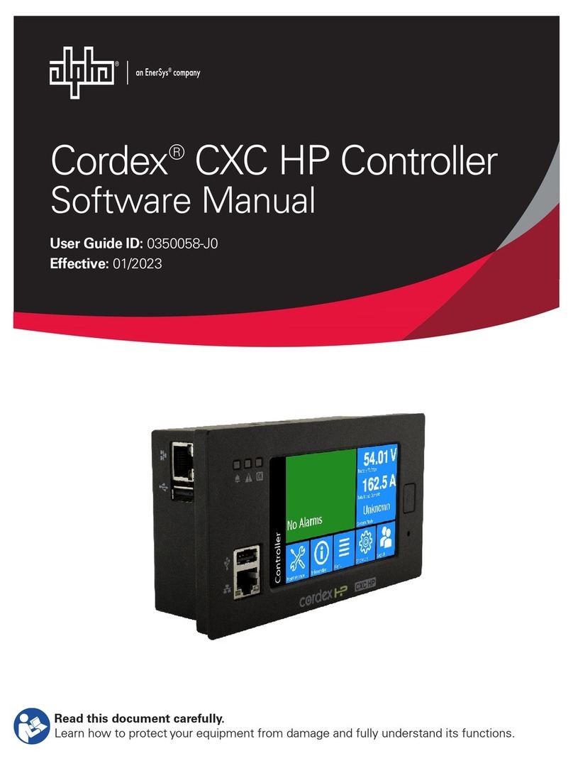
Cordex®CXC HP Controller
Modbus Integrator Guide
User Guide ID: 0350114-J0
Eective:01/2023
Read this document carefully.
Learn how to protect your equipment from damage and fully understand its functions.

NOTICE
For the latest version of software, firmware, and product documentation, visit the Alpha®
website, www.alpha.com or www.alpha.ca.
NOTICE
Photographs contained in this document are for illustrative purposes only. These photographs
may not match your installation.
NOTICE
Operator is cautioned to review the drawings and illustrations contained in this document before
proceeding. If there are questions regarding the safe operation of this powering system, contact
Alpha Technologies Ltd. or your nearest Cordex® power system representative.
NOTICE
Alpha Technologies Ltd. shall not be held liable for any damage or injury involving its enclosures,
power supplies, generators, batteries, or other hardware if used or operated in any manner or
subject to any condition inconsistent with its intended purpose, or if installed or operated in an
unapproved manner, or improperly maintained.
Copyright notice
© 2023 Alpha Technologies Ltd., an EnerSys company. All Rights Reserved. Trademarks and logos are the property
of EnerSys and its affiliates. Subject to revisions without prior notice. E.&O.E.
No part of this documentation shall be reproduced, stored in a retrieval system, translated, transcribed, or
transmitted in any form or by any means manual, electric, electronic, electromechanical, chemical, optical, or
otherwise without prior explicit written permission from
Alpha Technologies Ltd.
This document, the software it describes, and the information and know-how they contain constitute the
proprietary, confidential and valuable trade secret information of Alpha, and may not be used for any unauthorized
purpose, or disclosed to others without the prior written permission of Alpha.
The material contained in this document is for information only and is subject to change without notice. While
reasonable efforts have been made in the preparation of this document to assure its accuracy, Alpha assumes no
liability resulting from errors or omissions in this document, or from the use of the information contained herein.
Alpha reserves the right to make changes in the product design without reservation and without notification to its
users.

Contents
List of Figures............................................................................................................................................... 3
List of Tables.................................................................................................................................................4
1. Safety....................................................................................................................................................... 6
2. Introduction............................................................................................................................................. 7
2.1. Overview.........................................................................................................................................7
2.2. Purpose and audience................................................................................................................... 7
2.3. Knowledge and permissions.......................................................................................................... 7
3. Using Modbus.........................................................................................................................................8
3.1. Modbus capabilities on the Cordex® CXC HP controller.............................................................. 8
3.2. Modbus setup.................................................................................................................................8
3.3. Modbus data.................................................................................................................................11
3.3.1. Limited data set................................................................................................................. 11
3.3.2. Full system data set...........................................................................................................11
3.4. How to create an identical Modbus structure.............................................................................. 13
3.5. Modbus reference........................................................................................................................ 14
3.5.1. Full system data set data points........................................................................................14
3.5.2. Limited data set data points.............................................................................................. 43
4. Glossary.................................................................................................................................................45
Page 2 0350114-J0 Rev N

Modbus Integrator's Guide for the Cordex® CXC HP Controller
List of Figures
Figure 3-1 Enabling the Modbus agent........................................................................................................9
Figure 3-2 Modbus connection configuration............................................................................................. 10
Figure 3-3 Modbus data example.............................................................................................................. 10
0350114-J0 Rev N Page 3

Modbus Integrator's Guide for the Cordex® CXC HP Controller
List of Tables
Table 3-1 Configuration................................................................................................................................ 9
Table 3-2 Modbus address allocation for common controller data............................................................ 11
Table 3-3 Modbus address allocation for DC system data........................................................................ 12
Table 3-4 Modbus address allocation for AMPS HP system data............................................................. 12
Table 3-5 Controller data points................................................................................................................. 14
Table 3-6 Custom data data points............................................................................................................15
Table 3-7 Timers data points......................................................................................................................15
Table 3-8 Counters data points.................................................................................................................. 16
Table 3-9 User alarms data points.............................................................................................................16
Table 3-10 Cordex® CXC HP L-ADIO data points.................................................................................... 16
Table 3-11 Cordex® CXC HP 6i-ADIO data points....................................................................................17
Table 3-12 Cordex® CXC HP HV-ADIO data points................................................................................. 18
Table 3-13 Cordex® I/M1 ADIO data points.............................................................................................. 19
Table 3-14 PSU ADIO data points............................................................................................................. 19
Table 3-15 Shunt Mux ADIO data points................................................................................................... 20
Table 3-16 8R/8D ADIO data points.......................................................................................................... 21
Table 3-17 BDFB ADIO data points...........................................................................................................22
Table 3-18 E2 ADIO data points................................................................................................................ 23
Table 3-19 FlexAir® ADIO data points.......................................................................................................24
Table 3-20 Smart Bypass ADIO data points.............................................................................................. 25
Table 3-21 Polarium Protocol Bridge data points.......................................................................................26
Table 3-22 DC system data points.............................................................................................................27
Table 3-23 DC system lead-acid battery data points................................................................................. 30
Table 3-24 DC System Polarium battery data points.................................................................................30
Table 3-25 DC system loads data points...................................................................................................31
Table 3-26 DC system disconnects data points.........................................................................................32
Table 3-27 DC system shunts data point...................................................................................................32
Table 3-28 DC system current transducer (CT) data point........................................................................33
Table 3-29 DC system rectifiers data points.............................................................................................. 33
Table 3-30 AMPS HP modular inverter system data points.......................................................................33
Table 3-31 AMPS HP modular inverter system bypass switch with XMBS data points............................. 41
Table 3-32 AMPS HP modular inverter system bypass switch data points............................................... 41
Page 4 0350114-J0 Rev N

Modbus Integrator's Guide for the Cordex® CXC HP Controller
Table 3-33 AMPS HP modular inverter system breakers/fuse data points................................................ 41
Table 3-34 AMPS HP modular inverter system T2S data points............................................................... 41
Table 3-35 AMPS HP modular inverter system TSI inverters data points................................................. 41
Table 3-36 Limited data set data points.....................................................................................................43
0350114-J0 Rev N Page 5

1. Safety
SAVE THESE INSTRUCTIONS: This document contains important safety instructions that must be
followed during the installation, servicing, and maintenance of the product. Keep it in a safe place. Review
the drawings and illustrations contained in this document before proceeding. If there are any questions
regarding the safe installation or operation of this product, contact Alpha Technologies Ltd. or the nearest
Alpha® power system representative.
Safety wording and symbols
To reduce the risk of injury or death, and to ensure the continued safe operation of this product, the
following symbols have been placed throughout this document. Where these symbols appear, use extra
care and attention.
Attention: The use of attention indicates specific regulatory or code requirements that may affect the
placement of equipment or installation procedures.
Note: Notices provide additional information to help complete a specific task or procedure.
Important: Follow the prescribed procedures to avoid equipment damage or service interruption.
CAUTION: Cautions indicate safety information intended to PREVENT DAMAGE to material or
equipment.
Warning: Warnings present safety information to PREVENT INJURY OR DEATH to personnel.
CAUTION: HOT! The use of Hot presents safety information to PREVENT BURNS to the technician
or user
General warning and cautions
Warning: You must read and understand the following warnings before installing the system and its
components. Failure to do so could result in personal injury or death.
•Read and follow all instructions included in this manual.
•Only trained personnel are qualified to install or replace this equipment and its components.
•Use proper lifting techniques whenever handling equipment, parts, or batteries.
Page 6 0350114-J0 Rev N

2. Introduction
2.1. Overview
The purpose of this document is to provide information on how to use Cordex® CXC HP system controller
and software along with Modbus. This document contains information on setup and operation of Modbus
using the controller.
2.2. Purpose and audience
The audience for this manual are engineers, technicians, IT professionals, and network operation
personnel who are tasked with remote monitoring of the power system using Modbus. They should be
well versed in the Modbus protocol as well as the network management, remote monitoring, or network
operations center software and tools that will be used to monitor the controller.
2.3. Knowledge and permissions
It is assumed that you have a good working knowledge of, and access to, the following:
•Modbus monitoring software and tools
•Ethernet cables and TCP/IP settings needed to connect your computer to the controller
•Current version of Google Chrome, Mozilla Firefox, Microsoft Internet Explorer/Edge, or Apple
Safari
•Power system that the controller currently controls
•Controller admin password and the appropriate level of permissions
0350114-J0 Rev N Page 7

3. Using Modbus
3.1. Modbus capabilities on the Cordex® CXC HP controller
A Modbus client connects to the controller over an Ethernet TCP/IP connection to request data. Modbus
RTU is not directly supported, but third-party devices are available to translate from TCP/IP to RTU and
vice versa. A Modbus request consists of a device ID, a register code, a register address, and a length.
The controller Modbus agent:
•Supports multiple device IDs. The DC system limited data set ID and a full data set ID for the DC
system and each AMPS HP2 modular inverter system. The data mapped to these sets are shown
in the Modbus reference section.
•Represents data in the coil status and input status registers as boolean data (0 or 1)
•Represents data in the input register as 32-bit floating point values. There is one exception to this:
serial numbers of modules like ADIO or rectifiers are displayed as 32-bit integers.
•Value returned for a register that does not contain data is 0.
•Value returned for a register that has unknown data, corresponding to ‘---’ on the controller UI, is
0xFFFFFFFF (or -1).
•Value returned for a status register that has been deprecated is 0.
•Value returned for an input register that has been deprecated is 999999999.
•Value returned for an input register that does not exist on the controller (but is needed for
backwards compatibility or cross-compatibility with other systems) is 0xFFFFFFFF (or -1).
The Modbus agent supports three of the four common registers per device ID:
1. Coil Status (01) to hold status of relays, range 1 to 9999.
2. Input Status (02) to hold status of boolean data like alarms or digital inputs, range 10001 to 19999.
3. Input Register (04) to hole numeric values, range 30001 to 39999.
The Holding Register (03) commonly used to write data, is not supported.
3.2. Modbus setup
To enable Modbus TCP/IP on the controller, you need to configure certain parameters:
To enable the Modbus Agent, go to Controller > Communication > Modbus. Select the EDIT button
next to Modbus Agent in the Configuration table and select Enabled in the dropdown list. Select the
EDIT button next to Byte Order to confugure the byte order.
Page 8 0350114-J0 Rev N

Modbus Integrator's Guide for the Cordex® CXC HP Controller | 3 - Using Modbus
Figure 3-1 Enabling the Modbus agent
Table 3-1 Configuration
Name Description
Modbus Agent Enables or disables Modbus service. When enabled, the service is initialized and
the controller is ready to accept requests. The controller serves data for both the
limited and full data set.
The default value is Disabled.
Internet Protocol The Internet Protocol IPv4 or IPv6 to be used for communication.
Byte Order Changes the byte order of 32-bit data. This setting is used to change whether the
most or least significant byte comes first. This setting should be set according
to the requirements of the Modbus client. The client will decode and format data
needed to understand the correct byte order. The default value is Least signifi-
cant bytes first.
Reverse the bytes for the input values registers (function code 4). These values
are stored as 32-bit floating point and occupy 2 registers each. By default the val-
ues are stored with least significant bytes first (little endian).
Limited Data Set ID This ID is a small set of DC system data. See the Modbus reference section for
the data mapping. The default is 247, the range is 241 to 250.
The data available through this device ID provides a limited view of the DC system
information.
Device ID This table has a device ID for each supported system. Device IDs are automatical-
ly assigned when systems are created. The devices IDs must be unique. See the
Modbus reference section for the data mapping. The range is 1 to 240.
Client application setup
Client applications connect to the controller through TCP/IP via a Modbus client. The standard Modbus
service port 502 is used. The sample application used for the following figure, is Modscan32 available at
WinTECH Software Design www.win-tech.com.
0350114-J0 Rev N Page 9

Modbus Integrator's Guide for the Cordex® CXC HP Controller | 3 - Using Modbus
Figure 3-2 Modbus connection configuration
Once a connection is made, data is polled automatically at the given device ID, address, and length as
shown.
Figure 3-3 Modbus data example
Device ID: Provides specific data of interest for that device ID.
Address: Provides the starting address of the data block.
Length: Provides the length of the data block.
Modbus Point Type: The register channel of the data. The example shows Command code 04 - Input
Register (read-only data).
Note: The data shown have “unknown” or unsupported values represented as the floating point value
of 0xFFFFFFFF (-1.#QB). Non-available data or data addresses that are not populated display as 0.
Page 10 0350114-J0 Rev N

Modbus Integrator's Guide for the Cordex® CXC HP Controller | 3 - Using Modbus
3.3. Modbus data
There are two types of data available over Modbus: limited data set and a full system data set for the DC
system and each AMPS HP2 modular inverter system.
3.3.1. Limited data set
The Limited Data Set has a small number of DC system related parameters. This data set uses only the
input registers table (04). The default Limited Data Set Device ID is 247. For a list of available data refer
to the Limited data set data points section.
3.3.2. Full system data set
A full system data set is available for the DC system and each AMPS HP2 modular inverter system. This
data set has all parameters related to the system as well as other data such as custom, data, timers,
counters, and ADIO readings. Three Modbus registers are used: coils status (01), input status (02), input
register (04). The default device ID is 1.
The structure of a full system data set is much different than for the Limited Data Set. When working with
the controller, it is possible to create and remove inventory to match a physical system, or to create and
remove things like user alarms, custom data, timers, and counters. Because of this dynamic nature there
are limits to the number of item that can be assigned Modbus addresses.
The data available for each device ID always includes controller data. The following tables show the types
of data contained in the Modbus table, the starting address for each type of data, and the limitation to the
number of data supported. Note that system data always starts at address 5001.
Table 3-2 Modbus address allocation for common controller data
Source Maximum num-
ber of source
items
Start of coil sta-
tus register (01)
Start of input
status register
(02)
Start of values
register (04)
Controller 1 1 10001 30001
Custom Data 128 203 10203 30203
Timers 128 717 10717 30717
Counters 128 1231 11231 31231
User alarms 64 1745 11745 31745
reserved 1 2003 12003 32003
ADIO 24 3541 13541 33541
0350114-J0 Rev N Page 11

Modbus Integrator's Guide for the Cordex® CXC HP Controller | 3 - Using Modbus
Table 3-3 Modbus address allocation for DC system data
Source Maximum num-
ber of source
items
Start of coil sta-
tus register (01)
Start of input
status register
(02)
Start of values
register (04)
DC System 1 5001 15001 35001
DC System: Battery 1 5157 15157 35157
DC System: Loads 120 5183 15183 35183
DC system: Shunt 120 6385 16385 36385
DC system: CT 120 6627 16627 36627
DC system: Discon-
nect
10 6869 16869 36869
DC system: Rectifier 256 6991 16991 36991
Table 3-4 Modbus address allocation for AMPS HP system data
Source Maximum num-
ber of source
items
Start of coil sta-
tus register (01)
Start of input
status register
(02)
Start of values
register (04)
AMPS HP System 1 5001 15001 35001
AMPS HP System :
Breakers/Fuses
10 6503 16503 36503
AMPS HP System :
Bypass Switch
5 6625 16625 36625
AMPS HP System :
T2S
4 6707 16707 36707
AMPS HP System :
Inverters
32 6773 16773 36773
This table shows:
•Source item that has Modbus data available
•Maximum number of items that can be viewed over Modbus in each register
•Starting address for each type of data.
Note: Modbus client software sometimes requires addresses to be entered in the range 1
to 9999. If this is the case, drop the leftmost digit for addresses that are greater than 9999. The
Modbus client software will then use the combination of register and address to formulate the
correct address for the query.
Page 12 0350114-J0 Rev N

Modbus Integrator's Guide for the Cordex® CXC HP Controller | 3 - Using Modbus
Not all register addresses will be populated with data. For example, the controller does not actually have
any coils (relays). A request for coil data at address 1 will return zero.
The Modbus reference table on the controller web interface provides specific addresses for particular data
points.
Modbus reference tables
Modbus addressing follows these rules when changing system configuration:
•When an item is created, such as custom data, or a shunt, the item is assigned Modbus addresses
for its data. These addresses will not change unless the item is removed, or the Re-number
Modbus Table by Name button is selected.
•Removing an item leaves a gap in the address table. If a new item is created, it will fill the next
available address. If there are no gaps, it is added to the end
•Modbus addresses are local to the controller. They cannot be transfered. If necessary, to align
Modbus addresses between identical or similar systems, see the procedure in the How to create
identical modbus structure section.
•When importing a configuration, the newly imported items are sorted by name first, then assigned
the first available Modbus address. Existing Modbus addresses are not changed.
3.4. How to create an identical Modbus structure
The dynamic nature of creating and configuring a controller means that Modbus addresses may not
be identical between identical systems. These instructions describe how to create the same Modbus
structure between identical systems. If you are using the Limited Data Set only, then the Modbus
addresses are already static and it is not necessary to follow these instructions. If you are using a full
Modbus system data set, follow these instructions:
0350114-J0 Rev N Page 13

Modbus Integrator's Guide for the Cordex® CXC HP Controller | 3 - Using Modbus
1. Create your system and configure all it's inventory, custom data, timers, counters, user alarms, and
ADIO module.
2. Name all your inventory (for example, shunts and loads), custom data, timers, counters, user
alarms, and ADIO module with a number as a prefix. For example, if you have two loads that you
have already named: “Radio (150W)” and “Juniper Router”. Change the names to “(01) Radio
(15W)” and “(02) Juniper Router”. This prefix helps to explicitly define the order of the Modbus
data. Note the format of the number (“01”) has a preceding zero. If there are more than nine items
of the same type, this preceding zero is required to ensure that the sorting is correct. If there are
more than 99 items of the same type, two preceding zeros are required (“001”).
It is not possible to apply names to power modules
3. Select the Re-number Modbus Table By Name button on the Full Data Set table. This sorts all
the Modbus data of the same type alphanumerically and reassigns addresses
4. Export a clone of the system and import it to another system. On import, the Modbus items are
sorted in the same way as is done when the Re-number Modbus Table By Name is selected.
5. Perform a Replace ADIO operation to transfer the ADIO configuration of an imported ADIO to an
existing ADIO
After importing the clone, the Modbus structure on the two identical systems is the same.
3.5. Modbus reference
3.5.1. Full system data set data points
This section lists the data points for each type of item that is available through Modbus. Because of the
dynamic nature of the configuration, it is not possible to show a static Modbus table with addresses for a
system. Use the Export to CSV button on the web interface to generate and download a Modbus table
with addresses for a specific system. Each table has three columns:
•Name: The name of the data.
•Register: The Modbus register where the data resides.
•Format: The format of the data. To display data correctly, Modbus clients must have the right data
format specified in the correct order.
3.5.1.1. Data points
Table 3-5 Controller data points
Name Register Format
Disk Almost Full 02:Input Status Boolean
Clock Error 02:Input Status Boolean
CAN Devices In Bootloader 02:Input Status Boolean
Page 14 0350114-J0 Rev N

Modbus Integrator's Guide for the Cordex® CXC HP Controller | 3 - Using Modbus
Table 3-5 Controller data points (continued)
Name Register Format
ADIO Comms Lost 02:Input Status Boolean
Temporary License In Use 02:Input Status Boolean
Temporary License Expired 02:Input Status Boolean
Required Feature License Missing 02:Input Status Boolean
Unassigned Modules 02:Input Status Boolean
Duplicate SNMP Component Refer-
ence
02:Input Status Boolean
Restart Required 02:Input Status Boolean
Number Of Bit Errors High 02:Input Status Boolean
Memory Usage High 02:Input Status Boolean
CAN Module Communication Lost
Count High
02:Input Status Boolean
CAN Module Communication Lost
Count Very High
02:Input Status Boolean
Controller: Time Since Restart 04:Input Register 32-bit Floating Point
Table 3-6 Custom data data points
Name Register Format
Custom Data: Result as Numeric 04:Input Register 32-bit Floating Point
Table 3-7 Timers data points
Name Register Format
Interval Timer: Output 02:Input Status Boolean
Delay Timer: Output 02:Input Status Boolean
Delay Timer: Delay Time Remain-
ing
04:Input Register 32-bit Floating Point
0350114-J0 Rev N Page 15

Modbus Integrator's Guide for the Cordex® CXC HP Controller | 3 - Using Modbus
Table 3-8 Counters data points
Name Register Format
Down Counter: Input 02:Input Status Boolean
Up Counter: Input 02:Input Status Boolean
Down Counter: Output 04:Input Register 32-bit Floating Point
Up Counter: Output 04:Input Register 32-bit Floating Point
Table 3-9 User alarms data points
Name Register Format
Threshold User Alarm/835: User-
Defined
02:Input Status Boolean
Digital User Alarm/547: User-De-
fined
02:Input Status Boolean
Table 3-10 Cordex® CXC HP L-ADIO data points
Name Register Format
K1 01:Coil Status Boolean
K2 01:Coil Status Boolean
K3 01:Coil Status Boolean
K4 01:Coil Status Boolean
K5 01:Coil Status Boolean
K6 01:Coil Status Boolean
K7 01:Coil Status Boolean
K8 01:Coil Status Boolean
K9 01:Coil Status Boolean
K10 01:Coil Status Boolean
K11 01:Coil Status Boolean
K12 01:Coil Status Boolean
D1 02:Input Status Boolean
Page 16 0350114-J0 Rev N

Modbus Integrator's Guide for the Cordex® CXC HP Controller | 3 - Using Modbus
Table 3-10 Cordex® CXC HP L-ADIO data points (continued)
Name Register Format
D2 02:Input Status Boolean
D3 02:Input Status Boolean
D4 02:Input Status Boolean
D5 02:Input Status Boolean
D6 02:Input Status Boolean
D7 02:Input Status Boolean
D8 02:Input Status Boolean
Temperature Sensor #1 Failure 02:Input Status Boolean
Temperature Sensor #2 Failure 02:Input Status Boolean
Temperature Sensor #3 Failure 02:Input Status Boolean
Temperature Sensor #4 Failure 02:Input Status Boolean
CAN Serial Number 04:Input Register 32-bit Integer
V1 04:Input Register 32-bit Floating Point
V2 04:Input Register 32-bit Floating Point
V3 04:Input Register 32-bit Floating Point
V4 04:Input Register 32-bit Floating Point
T1 04:Input Register 32-bit Floating Point
T2 04:Input Register 32-bit Floating Point
T3 04:Input Register 32-bit Floating Point
T4 04:Input Register 32-bit Floating Point
I1 04:Input Register 32-bit Floating Point
I2 04:Input Register 32-bit Floating Point
I3 04:Input Register 32-bit Floating Point
I4 04:Input Register 32-bit Floating Point
Table 3-11 Cordex® CXC HP 6i-ADIO data points
Name Register Format
CAN Serial Number 04:Input Register 32-bit Integer
0350114-J0 Rev N Page 17

Modbus Integrator's Guide for the Cordex® CXC HP Controller | 3 - Using Modbus
Table 3-11 Cordex® CXC HP 6i-ADIO data points (continued)
Name Register Format
I1 04:Input Register 32-bit Floating Point
I2 04:Input Register 32-bit Floating Point
I3 04:Input Register 32-bit Floating Point
I4 04:Input Register 32-bit Floating Point
I5 04:Input Register 32-bit Floating Point
I6 04:Input Register 32-bit Floating Point
Table 3-12 Cordex® CXC HP HV-ADIO data points
Name Register Format
K1 01:Coil Status Boolean
K2 01:Coil Status Boolean
K3 01:Coil Status Boolean
K4 01:Coil Status Boolean
K5 01:Coil Status Boolean
K6 01:Coil Status Boolean
D1 02:Input Status Boolean
D2 02:Input Status Boolean
D3 02:Input Status Boolean
D4 02:Input Status Boolean
Temperature Sensor #1 Failure 02:Input Status Boolean
Temperature Sensor #2 Failure 02:Input Status Boolean
Ground Fault Resistance Low 02:Input Status Boolean
Ground Fault Current High 02:Input Status Boolean
CAN Serial Number 04:Input Register 32-bit Integer
GFD Current 04:Input Register 32-bit Floating Point
V1 04:Input Register 32-bit Floating Point
V2 04:Input Register 32-bit Floating Point
T1 04:Input Register 32-bit Floating Point
Page 18 0350114-J0 Rev N

Modbus Integrator's Guide for the Cordex® CXC HP Controller | 3 - Using Modbus
Table 3-12 Cordex® CXC HP HV-ADIO data points (continued)
Name Register Format
T2 04:Input Register 32-bit Floating Point
I1 04:Input Register 32-bit Floating Point
DCCT1 04:Input Register 32-bit Floating Point
DCCT2 04:Input Register 32-bit Floating Point
Table 3-13 Cordex® I/M1 ADIO data points
Name Register Format
K1 01:Coil Status Boolean
K2 01:Coil Status Boolean
K3 01:Coil Status Boolean
K4 01:Coil Status Boolean
D1 02:Input Status Boolean
D2 02:Input Status Boolean
Temperature Sensor #1 Failure 02:Input Status Boolean
Temperature Sensor #2 Failure 02:Input Status Boolean
CAN Serial Number 04:Input Register 32-bit Integer
V1 04:Input Register 32-bit Floating Point
V2 04:Input Register 32-bit Floating Point
T1 04:Input Register 32-bit Floating Point
T2 04:Input Register 32-bit Floating Point
I1 04:Input Register 32-bit Floating Point
Table 3-14 PSU ADIO data points
Name Register Format
K1 01:Coil Status Boolean
K2 01:Coil Status Boolean
K3 01:Coil Status Boolean
0350114-J0 Rev N Page 19
Other manuals for Alpha Cordex CXC HP
1
Table of contents
Other EnerSys Controllers manuals
Popular Controllers manuals by other brands

Future Design
Future Design MCT-MC 4.3 user manual
CNC4PC
CNC4PC PLASMA THC-3 user manual

Advantech
Advantech ADAM-5550KW Series user manual

Samson
Samson 43-8 Mounting and operating instructions
Koei Industry
Koei Industry Nucom L50S Operation manual
National Instruments
National Instruments sbRIO-9637 user manual

Altronix
Altronix T2RM7CK1 installation guide
Integra
Integra Integra Research RDC-7.1 instruction manual
Carrier
Carrier SYSTEM PILOT 33PILOT-01 owner's manual
Honeywell
Honeywell PW6K1ICE Installation and configuration guide
Mitsubishi Electric
Mitsubishi Electric MS-T Series instruction manual
Athena
Athena 18C Series user guide
