Samson 43-8 Service manual

Translation of original instructions
EB 2178 EN
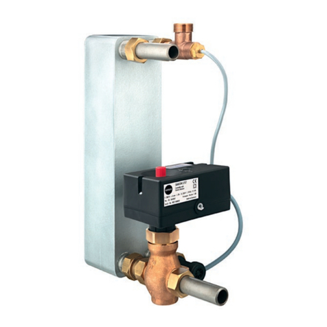
Type43-8 Temperature Regulator with Hydraulic Controller
Edition May 2023

Definition of signal words
Hazardous situations which, if not avoided,
will result in death or serious injury
Hazardous situations which, if not avoided,
could result in death or serious injury
Property damage message or malfunction
Additional information
Recommended action
DANGER
!
WARNING
!
NOTICE
!
Note
Tip
EB 2178 EN
Note on these mounting and operating instructions
These mounting and operating instructions assist you in mounting and operating the device
safely. The instructions are binding for handling SAMSON devices. The images shown in
these instructions are for illustration purposes only. The actual product may vary.
ÎFor the safe and proper use of these instructions, read them carefully and keep them for
later reference.
ÎIf you have any questions about these instructions, contact SAMSON‘s After-sales Service
(aftersalesservice@samsongroup.com).
Documents relating to the device, such as the mounting and operating
instructions, are available on our website at www.samsongroup.com >
Service & Support > Downloads > Documentation.

Contents
EB 2178 EN
1 Safety instructions and measures ...................................................................4
1.1 Notes on possible severe personal injury .........................................................7
1.2 Notes on possible personal injury ...................................................................7
1.3 Notes on possible property damage................................................................8
2 Markings on the device .................................................................................9
2.1 Materialidenticationnumber ......................................................................10
3 Design and principle of operation ................................................................10
3.1 Technical data .............................................................................................11
3.1.1 Process medium and scope of application......................................................11
4 Measures for preparation............................................................................15
4.1 Unpacking ..................................................................................................15
4.2 Transporting and lifting ................................................................................15
4.3 Storage.......................................................................................................15
4.4 Preparation for installation............................................................................16
5 Mounting and start-up.................................................................................16
5.1 Assembling the valve, hydraulic controller and control thermostat ....................16
5.2 Mounting positions.......................................................................................17
5.2.1 Installing the valve and hydraulic controller....................................................17
5.2.2 Installing the control thermostat .....................................................................19
5.3 Additionalttings.........................................................................................20
5.4 Start-up.......................................................................................................21
6 Operation...................................................................................................22
6.1 Adjusting the set point at the control thermostat..............................................22
7 Servicing.....................................................................................................23
7.1 Tightening torques and lubricant ...................................................................23
7.2 Preparation for return shipment.....................................................................23
8 Malfunctions ...............................................................................................23
9 Decommissioning and removal ....................................................................25
9.1 Decommissioning.........................................................................................26
9.2 Disposal......................................................................................................26
10 Annex.........................................................................................................27
10.1 After-sales service and spare parts ................................................................27
11 Certicates..................................................................................................27

4 EB 2178 EN
Safety instructions and measures
1 Safety instructions and measures
Intended use
TheType2438HydraulicControllerwithType2432ValveandType2430Control
Thermostat is designed for temperature control of the energy supply to heat generators (e.g.
heat exchangers) by closing the valve. The regulator is mainly used to control the temperature
in instantaneous water heaters in small district heating units.
Thedevicesaredesignedtooperateunderexactlydenedconditions(e.g.operating
pressure, process medium, temperature). Therefore, operators must ensure that the devices
areonlyusedinoperatingconditionsthatmeetthespecicationsusedforsizingthedevices
at the ordering stage. In case operators intend to use the devices in applications or
conditionsotherthanthosespecied,contactSAMSON.
SAMSON does not assume any liability for damage resulting from the failure to use the de-
vice for its intended purpose or for damage caused by external forces or any other external
factors.
ÎRefertothetechnicaldataandnameplateforlimitsandeldsofapplicationaswellas
possible uses.
Reasonably foreseeable misuse
Thedevicesarenotsuitableforuseoutsidethelimitsdenedduringcongurationandbythe
technical data. Furthermore, the following activities do not comply with the intended use:
− Use of non-original spare parts
− Performing service and repair work not described
Qualications of operating personnel
The devices must be mounted, started up, serviced and repaired by fully trained and
qualiedpersonnelonly;theacceptedindustrycodesandpracticesaretobeobserved.
According to these mounting and operating instructions, trained personnel refers to
individualswhoareabletojudgetheworktheyareassignedtoandrecognizepossible
hazardsduetotheirspecializedtraining,theirknowledgeandexperienceaswellastheir
knowledge of the applicable standards.

EB 2178 EN 5
Safety instructions and measures
Personal protective equipment
Werecommendcheckingthehazardsposedbytheprocessmediumbeingused(e.g.
uGESTIS(CLP)hazardoussubstancesdatabase).
ÎProvide protective equipment (e.g. safety gloves, eye protection) appropriate for the pro-
cess medium used.
ÎWear hearing protection when working near the valve. Follow the instructions given by
the plant operator.
ÎCheckwiththeplantoperatorfordetailsonfurtherprotectiveequipment.
Revisions and other modications
Revisions,conversionsorothermodicationsoftheproductarenotauthorizedbySAMSON.
Theyareperformedattheuser'sownriskandmayleadtosafetyhazards,forexample.Fur-
thermore, the product may no longer meet the requirements for its intended use.
Warning against residual hazards
To avoid personal injury or property damage, plant operators and operating personnel must
preventhazardsthatcouldbecausedintheregulatorbytheprocessmedium,theoperating
pressure or by moving parts by taking appropriate precautions. Plant operators and operat-
ingpersonnelmustobserveallhazardstatements,warningsandcautionnotesinthese
mounting and operating instructions.
Hazardsresultingfromthespecialworkingconditionsattheinstallationsiteoftheregulator
mustbeidentiedinariskassessmentandpreventedthroughthecorrespondingsafetyin-
structions drawn up by the operator.
Wealsorecommendcheckingthehazardsposedbytheprocessmediumbeingused(e.g.
uGESTIS(CLP)hazardoussubstancesdatabase).
ÎObservesafetymeasuresforhandlingthedeviceaswellasrepreventionandexplosion
protection measures.
These mounting and operating instructions deals with the standard version of the device.
Componentsofthedevicethatdiffertothoseusedforthestandardversiondescribedinthis
documentcanbeexchangedwithothercertainSAMSONcomponents.Theresidualhazards
of these components are described in the associated mounting and operating instructions
(see documents listed under 'Referenced documentation').

6 EB 2178 EN
Safety instructions and measures
Responsibilities of the operator
Operators are responsible for proper use and compliance with the safety regulations.
Operators are obliged to provide these mounting and operating instructions as well as the
referenced documents to the operating personnel and to instruct them in proper operation.
Furthermore, operators must ensure that operating personnel or third parties are not exposed
to any danger.
Operatorsareadditionallyresponsibleforensuringthatthelimitsfortheproductdenedin
the technical data are observed. This also applies to the start-up and shutdown procedures.
Start-up and shutdown procedures fall within the scope of the operator's duties and, as such,
are not part of these mounting and operating instructions. SAMSON is unable to make any
statements about these procedures since the operative details (e.g. differential pressures and
temperatures) vary in each individual case and are only known to the operator.
Responsibilities of operating personnel
Operating personnel must read and understand these mounting and operating instructions as
wellasthereferenceddocumentsandobservethespeciedhazardstatements,warnings
and caution notes. Furthermore, operating personnel must be familiar with the applicable
health, safety and accident prevention regulations and comply with them.
Referenced standards, directives and regulations
The devices comply with the requirements of the European Pressure Equipment Directive
2014/68/EU.DeviceswithaCEmarkinghaveanEUdeclarationofconformity,whichin-
cludes information about the applied conformity assessment procedure. The EU declaration
ofconformityisincludedintheannexoftheseinstructions(seesection11).
Non-electric valve versions whose bodies are not lined with an insulating material coating do
nothavetheirownpotentialignitionsourceaccordingtothehazardassessmentstipulatedin
Clause5.2ofISO80079-36,evenintherareincidentofanoperatingfault.Therefore,such
valve versions do not fall within the scope of Directive 2014/34/EU.
ÎForconnectiontotheequipotentialbondingsystem,observetherequirementsspeciedin
Clause6.4ofEN60079-14(VDE0165-1).
Referenced documentation
The following documents apply in addition to these mounting and operating instructions:
− Mounting and operating instructions for the valve uEB2171
− Mounting and operating instructions for the control thermostat uEB2430-3

EB 2178 EN 7
Safety instructions and measures
1.1 Notes on possible severe personal injury
DANGER
!
Risk of bursting in pressure equipment.
Valvesandpipelinesarepressureequipment.Improperopeningcanleadtovalve
components bursting.
ÎBeforestartinganyworkonthevalve,depressurizeallplantsectionsaffectedas
well as the valve.
ÎDrain the process medium from all the plant sections affected as well as the valve.
ÎWear personal protective equipment.
1.2 Notes on possible personal injury
WARNING
!
Risk of personal injury due to residual process medium in the valve.
While working on the valve, residual process medium can escape and, depending on
its properties, may lead to personal injury, e.g. burns.
ÎIf possible, drain the process medium from all the plant sections affected and the
valve.
ÎWear protective clothing, safety gloves and eye protection.
Risk of burn injuries due to hot or cold components and pipelines.
Depending on the process medium, valve components and pipelines may get very hot
or cold and cause burn injuries.
ÎAllow components and pipelines to cool down or warm up to the ambient tempera-
ture.
ÎWear protective clothing and safety gloves.
Damage to health relating to the REACH regulation.
If a SAMSON device contains a substance listed as a substance of very high concern
onthecandidatelistoftheREACHregulation,thisisindicatedontheSAMSONdeliv-
ery note.
ÎInformation on safe use of the part affected
uhttps://www.samsongroup.com/reach-en.html.

8 EB 2178 EN
Safety instructions and measures
1.3 Notes on possible property damage
NOTICE
!
Risk of irreparable regulator damage caused by the regulator components being
taken apart.
The thermostat, set point adjuster and capillary tube form an inseparable hydraulic
unit. If these components are dismantled (e.g. removal of the capillary tube), the regu-
latorwillbeirreparablydamagedandwillnolongerbeabletofulllitsmonitoring
and control task.
ÎDo not dismantle the regulator.
ÎOnly perform allowed activities on the regulator.
ÎContactSAMSON'sAfter-salesServicebeforereplacingspareparts.
Risk of valve damage due to contamination (e.g. solid particles) in the pipeline.
The plant operator is responsible for cleaning the pipelines in the plant.
ÎFlush the pipelines before start-up.
ÎObserve the maximum permissible pressure for valve and plant.
Risk of valve damage due to unsuitable medium properties.
Thevalveisdesignedforaprocessmediumwithdenedproperties.
ÎOnlyusetheprocessmediumspeciedforsizingtheequipment.
Risk of leakage and valve damage due to excessively high or low tightening
torques.
Observethespeciedtorqueswhentighteningvalvecomponents.
Excessive tightening torques lead to parts wearing out more quickly. Parts that are too
loose may cause leakage.
ÎObservethespeciedtighteningtorques.

EB 2178 EN 9
Markings on the device
2 Markings on the device
Type2438 Hydraulic Controller
Specications on the valve
1Date of manufacture
2CongurationID
3Device index
2 – 3
2438 1
PN16 SAMSON
Type2430 Control Thermostat
Specications on the scaled cap on the adjustment knob to adjust the set point
1Model number/type designation
2CongurationID
3Setpointrangein°Cand°F
4Register number (type test
accordingtoDINEN14597)
SAMSON
2750-0
2430
1067861
...°C
...°F
TR(TL)
1
2
3
4
Type2432 Valve
Specications on the valve
1Type designation (valve)
2CongurationID
3Date of manufacture
4KVS/CV
5Max. permissible temperature
6Pressure rating (valve)
7Max.perm.differentialpressure∆p
SAMSON 1
2710 - 23
45
6 7
Fig.1: Nameplates

10 EB 2178 EN
Design and principle of operation
2.1 Material identication
number
SpecifyingthecongurationID,youcancon-
tactustondoutwhichmaterialisused.The
congurationID(2)isspeciedonthename-
plate.
For more details on the nameplate, see
Fig.1.
3 Design and principle of
operation
TheType43-8Regulatorisusedtocontrol
the temperature of instantaneous water heat-
ers in small district heating units.
ThedevicesconsistoftheType2430Control
Thermostat (30) operating according to the
vaporpressureprinciple,theType2438
HydraulicController(20)theType2432
Valve(1).
Thetemperaturesensorislledwithaliquid
which evaporates depending on the tem-
perature. As a result, a pressure in propor-
tion to the temperature is created in the sen-
sor. This pressure is transferred through the
capillary tube (8) to the operating element
(13) and converted into a positioning force,
which is compared to the force of the set
point spring (10).
The force ratio causes the plug in the valve
(1) to move. Depending on the valve travel,
an annular gap forms between the seat (2)
andtheplug(3)thatdeterminestheow
rate of the heating water.
A temperature increase at the sensor causes
the valve plug to close, thus reducing the
owrateoftheheatingwater.
Upon tapping hot water, a pressure differ-
enceof∆p=p1– p2is created above the
bafeplate(6).Theresultingforceopposes
the force of the compression spring (7) that
acts in closing direction and causes the valve
to open. Once hot water tapping has been
completed, the pressure balance is restored.
The force of the compression spring causes
the valve plug to move in the closing direc-
tionandtheheatowisinterrupted.Atthe
same time, the temperature set point of the
thermostatdropsbyapprox.8K(optionally
15K)toreachthereducedidletemperature.
This prevents reheating with temperature
peaks as well as the supply lines from cool-
ing down.
This ensures that hot water is immediately
available for the next tapping.
Table1: Domestic water quality
DHW
pH Min. 7/max. 10
Chlorideconcentration Max.150mg/l
HCO –
3
SO 2-
4
>1.5
Carbonatehardness Min.5°dH(German
hardness)
Total hardness Max.12°dH

EB 2178 EN 11
Design and principle of operation
3.1 Technical data
3.1.1 Process medium and
scope of application
TheType43-8TemperatureRegulatorissuit-
able for the control of liquids in instanta-
neous water heaters in small district heating
units.
For a temperature range from 45 to 65°C
ValveDN15·PN251)·Suitableforhot
water up to 130°C1)
_
1) Type43-8Nforlocalheatsupply:PN16and
120°Conly
The valve closes when the temperature rises
abovethesetpointoftheType2430Control
Thermostat.
Application range
The quality of the domestic water to be con-
trolleddeterminestheeldofapplicationof
the regulator. The water quality must meet
thefollowingrequirements(seeTable1).
Dimensions in mm · Weights in kg
The lengths and heights in the dimensional
drawingareshowninFig.3.
16
4
5
3
2
13
12
11
10
9
8
7
6
1
15
p
1
p2
14
17
18
19
Fig.2: Sectional drawing
1Valvebody
2Valveseat
3Plug
4Plug stem
5Valvespring
6Bafeplate
7Compressionspring
8Capillarytube
9Set point adjuster
10 Set point spring
11 Operating bellows
12 Pin of operating
element
13 Operating element
14
Coldwater
connection
(corrugated pipe)
drawn turned by 90°
15 Screwtting
16 Fastening screws
19 Lead-sealhole
20 Hydrauliccontroller
30 Controlthermostat

12 EB 2178 EN
Design and principle of operation
Table2: Technical data
Type2432 Valve Type43-8 Type43-8N
Valvesize DN15
KVScoefcient 2.5
Pressure rating PN25 PN16
Max.perm.differentialpressureΔp 20bar 6bar
Max. permissible valve temperature 130°C 120°C
Type2430 Control Thermostat
Set point range 45to65°C
Capillarytube 2m(5masspecialversion)
Max. perm. temperature at the sensor 30Kabovetheadjustedsetpoint
Max. perm. temperature at the set point
adjuster 35°C
Perm. pressure at sensor PN40
Type2438 Hydraulic Controller
Required differential pressure (pressure loss)
across the control unit on the cold water side
0.4barwithatappingrateupto10l/minute
0.5barwithatappingrateupto20l/minute
Pressure rating PN16
Idle temperature Approx.8K(optional15K)belowtheadjustedset
point
Min.temperaturedifferencebetweenow
temperature and temperature set point 10K
Max.owrate 20l/minute

EB 2178 EN 13
Design and principle of operation
Table3: Materials · Material numbers according to DIN EN
Body CC499K (red brass, Rg5) CW602N (hot-pressed brass)
Valveseat Stainless steel 1.4305 CW602N
Valveplug 1.4104andbrass,resistanttodezincication,withEPDMsoftseal
Valvespringandspringin
Type2438 Stainless steel 1.4310
Bafeplate POM
Temperature
sensor
Capillarytube Copper
Sensor CrNiMosteel
Set point adjuster PETP,glassberreinforced
Table4: Dimensions in mm · Weights in kg
Type43-8 Type43-8N
Length L 65
AF 30
Height H1 30
Type2432/2438/2430
H241 221
kg (approx.) 3.7 3.4

14 EB 2178 EN
Design and principle of operation
Dimensional drawings
Ø 12
Ø 76 G¾ /G1
G¾
G¾
Ø 18
L
43 1)
19 15 35
65
190
H1
H
Fig.3: Dimensional drawings for Type43-8 and Type43-8N

EB 2178 EN 15
Measures for preparation
4 Measures for preparation
After receiving the shipment, proceed as fol-
lows:
1. Checkthescopeofdelivery.Compare
the shipment received with the delivery
note.
2. Checktheshipmentfortransportation
damage. Report any damage to
SAMSON and the forwarding agent
(refer to delivery note).
4.1 Unpacking
Do not remove the packaging until immedi-
ately before installation.
Proceed as follows to lift and install the de-
vice:
1. Remove the packaging from the device.
2. Dispose of the packaging in accordance
with the valid regulations.
4.2 Transporting and lifting
Due to the low service weight, lifting equip-
ment is not required to transport and lift the
Type43-8andType43-8NTemperature
Regulators.
Transport instructions
− Protectthedeviceagainstexternalinu-
ences (e.g. impact).
− Protect the device against moisture and
dirt.
Note
− Observe the permissible ambient tem-
peratures(seesection3.1).
4.3 Storage
Risk of temperature regulator damage due
to improper storage.
− Observe the storage instructions.
− Avoid long storage times.
− Contact SAMSON in case of different
storage conditions or longer storage
times.
We recommend to regularly check the de-
vice and the prevailing storage conditions
during long storage periods.
Storage instructions
− Protect the temperature regulator
againstexternalinuences(e.g.im-
pact).
− Protect the device against moisture and
dirt. Store it at a relative humidity of
lessthan75%.Indampspaces,pre-
vent condensation. If necessary, use a
drying agent or heating.
− Make sure that the ambient air is free
of acids or other corrosive media.
− Observe the permissible ambient tem-
peratures(seesection3.1).
− Do not place any objects on the device.
NOTICE
!
Note

16 EB 2178 EN
Mounting and start-up
SAMSON's After-sales Service can provide
more detailed storage instructions on re-
quest.
4.4 Preparation for installation
Proceed as follows:
ÎCheckallconnectionsforthevalve,hy-
draulic controller and control thermostat.
ÎCheckallpartsfordamage.
ÎChecktomakesurethatthetypedesig-
nation, pressure rating and temperature
range of the valve, hydraulic controller
and control thermostat match the plant
conditions (pressure rating of the pipe-
line, medium temperature etc.).
ÎCheckanymountedthermometersto
make sure they function.
Tip 5 Mounting and start-up
Risk of overheating due to excessive
ambient temperatures or insufcient heat
dissipation when components are insulated.
− Do not include the temperature regulator in
the insulation of the pipeline.
5.1 Assembling the valve,
hydraulic controller and
control thermostat
TheType43-8/Type43-8NTemperature
RegulatorconsistsoftheType2432Valve
(1),Type2438HydraulicController(20)
andType2430ControlThermostat(30).
The hydraulic controller and the control
thermostat can be attached to the valve body
either before or after the valve is installed in
the pipeline.
On installation, make sure that the tempera-
ture does not exceed the max. permissible
ambienttemperatureof35°C.
Install the plate heat exchanger in such a
waythattheheatingwaterowsvertically
between the plates.
Heat exchanger connections
For district heating supply (heating water)
and hot water (top connection),
for district heating return (heating water)
and cold water (bottom connection)
NOTICE
!NOTICE
!

EB 2178 EN 17
Mounting and start-up
5.2 Mounting positions
Install the Type43-8 and Type43-8N in a
horizontalpositionwithcontrolthermostat
facing upward onto the heat exchanger.
Installation conditions
− Install the heat exchanger in the upright
position only with the heating water sup-
plyatthetop(seeFig.4).
− Chooseaplaceofinstallationthatallows
you to freely access the regulator even
after the entire plant has been complet-
ed.
− Makesurethedirectionofowmatches
the direction indicated by the arrow on
the body.
− Install the regulator free of stress and
with the least amount of vibrations as
possible.
− Observe the permissible ambient tem-
peratureofmax.50°C.
5.2.1 Installing the valve and
hydraulic controller
See Fig.2 and Fig.4.
1. Place the body of the hydraulic controller
on the valve connection. Slightly
hand-tighten the three side mounting
screws (16) so that that the hydraulic
controller can still be rotated on the
valve.
2. Mount and align the valve with double
nut (D) at the heat exchanger. Observe
thetighteningtorquesspeciedinsec-
tion7.1.
3. Attach the corrugated pipe (W) between
the hydraulic controller and cold water
connection of the heat exchanger. Ob-
servethetighteningtorquesspeciedin
section7.1.
4. When integrating a circulation pipe, the
necessary connection piece is available
(accessories). It is mounted between the
connection of the hydraulic controller
and the corrugated pipe (W). Observe
thetighteningtorquesspeciedinsec-
tion7.1.
Older regulator versions are equipped
with a capillary tube instead of the cor-
rugated pipe. The capillary tube (Ø18)
must only be used as a spare part.
5. Tighten the three side mounting screws
(16) at the hydraulic controller. Observe
thetighteningtorquesspeciedinsec-
tion7.1.

18 EB 2178 EN
Mounting and start-up
5 mm
F
DWA
a
H
W
Heatexchanger
connections
View A
Heatingwa-
ter supply
Hot
water
Heating
water return Cold
water
Heatexchanger
To hot water
tapping point
Coldwater
connection
M
View A
Notch
Connections
G¾orG1
AWelding end
DDouble nut
FSensor pocket
MGrubscrew
WCorrugatedpipe
Fig.4: Arrangement of Type43-8 with accessories (without circulation)
Table5: Installation dimensions · Dimensions in mm
Type 43-8 43-8N
aG¾ 40to45mm
G1 73to79mm
HW≥260mm ≥240mm
M M5 grub screw

EB 2178 EN 19
Mounting and start-up
5.2.2 Installing the control thermostat
The Type2430 is installed without thermowell.
To fully use the fast response behavior of the sensor (vapor pressure), the sensor must also be
installed at the best possible location.
In plate heat exchangers, this location is directly upstream of the outlet where the heated wa-
terowsoutoftheheatexchanger.
ÎThenotchattheendofthesensormustpointupward(seeFig.5).
A
Plate heat exchanger Hotwateroutlet
Adapter with temperature
sensor
View A
Temperature sensor, notch facing
upward
max. ±5°
5mm
Fig.5: Arrangement of Type2430 Control Thermostat for Type43-8
Note

20 EB 2178 EN
Mounting and start-up
ÎInstall the sensor pocket (F) in such a way
thatthesensorreacheshorizontallyinto
the hot water duct.
ÎObserveadistanceofapprox.5mmbe-
tween the tip of the sensor and the rear
of the housing.
ÎAfter aligning the sensor, clamp it with
the threaded pin (M). Observe the tight-
eningtorquesspeciedinsection7.1.
In hot water generating systems with instan-
taneous water heater, thermostatic mixer
faucets must not be installed downstream of
the temperature regulator as this may lead to
an instable temperature control.
Risk of capillary tube damage due to incor-
rect handling.
− Do not shorten the capillary tube.
− Roll up excess tube to form a ring. The
smallest bending radius is 50mm.
Observe the permissible ambient tempera-
ture of max. 50°C over the entire length of
the capillary tube.
5.3 Additional ttings
Strainer
Astrainerinstalledupstreamintheowpipe
holds back any dirt or other foreign particles
Note
NOTICE
!
Note
carried along by the medium. For example,
theSAMSONType1NIStrainerissuitable
(uT1010).
The following points must be observed when
installing the strainer:
− Do not use the strainer to permanently
ltertheprocessmedium.
− Install the strainer upstream of the regu-
lator.
− Allowsufcientspacetoremovethelter.
− Observetheowdirection.
− Inhorizontalpipelineswithgasesorliq-
uids,thelterelementfacesdownward.
Thelterelementfacessidewaysinap-
plications with steam.
− Install strainers in vertical pipelines with
themediumowingupwardwiththe
drain plug facing upward.
Remember to leave enough space to remove
the lter element for cleaning.
Shut-off valve
Install a hand-operated shut-off valve on the
inlet and outlet sides. This allows the plant to
be shut down for cleaning and maintenance,
and when the plant is not used for longer
periodsoftime(seeFig.6).
Thermometer
Install a thermometer both upstream and
downstream of the heat exchanger to moni-
tor the temperatures prevailing in the plant
(seeFig.6).
Tip
Table of contents
Other Samson Controllers manuals

Samson
Samson TROVIS 5500 User manual

Samson
Samson EB 2111 Setup guide

Samson
Samson 42-37 Service manual

Samson
Samson EB 31a Service manual

Samson
Samson TROVIS 3730-1 Service manual

Samson
Samson TROVIS 5500 Service manual

Samson
Samson 45-1 Service manual

Samson
Samson 45-6 User manual

Samson
Samson 2357-3 Service manual

Samson
Samson Type 4708 Service manual

Samson
Samson TROVIS 5433 User manual

Samson
Samson 3374 Service manual
Samson
Samson 2469 Service manual

Samson
Samson 46-5 Service manual

Samson
Samson 3725 series Service manual

Samson
Samson TROVIS 5757-3 Service manual

Samson
Samson 3730-4 User manual

Samson
Samson 3375 Service manual

Samson
Samson TROVIS 5757-3 Service manual

Samson
Samson 42-20 Service manual