SECOP 101N08 Series User manual

CONTROLLER FOR
BD COMPRESSORS
Flexible control settings
TOOL COOL
4
OPERATING INSTRUCTIONS
101N08xx Series, 12-24 V DC
WE HAVE MORE THAN 30
YEARS OF EXPERIENCE,
DEVELOPING DIRECT
CURRENT COMPRESSORS
AND HELPING CUSTOMERS
BENEFIT FROM THE
OPPORTUNITIES OF
MOBILE REFRIGERATION
TECHNOLOGY.
WITH A DEEP INSIGHT OF
THE USAGE ACROSS VARIOUS
APPLICATIONS WE HAVE
EARNED A POSITION AS
MARKET LEADER, WORKING
WITH OEM-CUSTOMERS .
www.secop.com SETTING THE STANDARD

2
Operating
Instructions
TABLE OF CONTENTS
1. Introduction ..............................................................................................3
1.1 Applications ...............................................................................................3
1.2 Capability ...................................................................................................3
1.3 Functions ...................................................................................................3
1.4 Programming Interface .............................................................................3
2. Installation ..............................................................................................4
2.1 Checklist ....................................................................................................4
2.2 Connect Cables .........................................................................................5
2.3 Install and Configure Software ...............................................................11
3. TOOL4COOL® Software Interface ............................................................. 27
3.1 User Interface ..........................................................................................27
3.2 Operation .................................................................................................27
4. Parameters ............................................................................................ 28
4.1 Parameter Overview ................................................................................28
4.2 Description of Parameters ......................................................................36
4.3 Error and Event Logs ..............................................................................46
5. Ordering ............................................................................................ 47

3
Operating
Instructions
The Secop BD compressors with 101N08xx Series 12-24V DC are designed for use in:
• Comfort cooling in parking anti-idle applications
• Spot and comfort cooling in buses, golf carts, smaller boats, forklifts, campers etc
• Cooling of switchboards and batteries in radio stations for cellular phones
• Mobile refrigeration applications
• Air cargo cooling
• Mobile cooling boxes of volume up to 1000L
• Mobile refrigeration applications
For R134a compressor variants:
One application module can control either single or twin compressor configurations.
The cooling capacity of the single compressor configuration is approx. 900 Watt @ Pe/Pc
~+15/+55°C
The cooling capacity of the twin compressor configuration is approx. 1800 Watt @ Pe/Pc
~+15/+55°C
The system is able to operate in ambient temperatures up to +55 ºC.
The operating conditions are High Back Pressure (HBP).
For R404A/R507 compressor variants:
The cooling capacity of the compressor is approx. 380 Watt @ Pe/Pc ~-5/+55°C
The system is able to operate in ambient temperatures up to +55 ºC.
The operating conditions are Low Back Pressure (LBP).
The main functions of the controllers are:
• Operation using either 12 V DC or 24 V DC
• Simultaneous and independent control of two compressors in twin configuration
• ECO function to optimize compressor speed for minimum power consumption
• Detailed error log
• Event log
• Motor / Compressor speed control
• Thermostat control (ON / OFF or electronic via NTC temperature sensor)
• Condenser fan control
• Evaporator fan control
• Communication interface
• Monitoring function
• Battery protection functions
• Main Switch
• Log of specific parameters
• Optimization of specific parameters via PC software before commencing mass production
The controller can be accessed using either
• The Secop software tool Tool4Cool® LabEdition, or
• A custom interface. Please contact Secop for further information regarding custom interfaces
1.
INTRODUCTION
1.1
Applications
1.2
Capability
1.3
Functions
1.4
Programming
Interface

4
Operating
Instructions
Installation involves the following steps:
• Checklist
• Cable connection
• Software installation and configuration
Ordering: See section 5.0
BD Controller 101N08xx Series 12-24 V DC
(modules and cables)
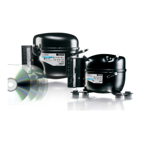
Image shows compressor/application
modules 101N08xx-series in twin
compressor configuration with
communication cable asembly
Tool4Cool® LabEdition software download:
www.secop.com/tool4cool.html
NTC temperature sensor
(alternative: mechanical thermostat)
Product key for BD compressor controller - on request -
Alternative gateways
Secop Bluetooth® gateway with
USB power supply
• Gateway
• USB power supply
• Bluetooth® connection cable
(must be ordered separately)
Secop One Wire/LIN gateway with
connection cables
• Gateway
• One Wire/LIN gateway
communication cable
• USB 2.0 A/B cable
Check that you have the following:
2.1
Checklist
2.
INSTALLATION

5
Operating
Instructions
Legend for 2.1 & 2.2
A. Application module 101N0820
B. Compressor module 101N0800, 12 V DC / compressor module 101N0810, 24 V DC
C. Line cords
D. Single or twin compressor communication cable assembly
1. Mounting screws
2. Battery
3. Fuse
4. Main switch
5. Evaporator fan
6. Condenser fan
7. Mechanical thermostat
8. NTC temperature sensor (electrical thermostat), alternative: mechanical thermostat
9. NTC auxiliary temperature sensor
10. Compressor(s)
11. Secop One Wire/LIN gateway communication interface
12. Modbus-compatible device
13. Secop Bluetooth® gateway communication interface
See Intructions DES.I.100.H_.02 for details.
2.2
Connect Cables

6
Operating
Instructions
2.2.1 Single compressor configuration, 12 V DC or 24 V DC, connect cables as shown:
With Display Module
With One Wire Gateway

7
Operating
Instructions
Wiring diagram
With Bluetooth® Gateway

8
Operating
Instructions
2.2.2 Twin compressor configuration, 12 V DC or 24 V DC, connect cables as shown:
With Display Module
With One Wire Gateway

9
Operating
Instructions
Wiring diagram
With Bluetooth® Gateway

10
Operating
Instructions
2.2.3 Connection between PC, one-wire gateway, and application module
Connect cables as shown:

11
Operating
Instructions
2.3.1 Install Software
2.3
Install and Configure
Software 1. Check that you have the latest update of .NET Framework from www.windowsupdate.com.
2. Insert the Tool4Cool® installation CD.
This view will appear:

12
Operating
Instructions
3. Double-click Tool4Cool® Software Installation. Run the file setup.exe. Then follow the
instructions in the Setup Wizard.
For detailed instructions please refer to Tool4Cool® LabEdition Operating Instructions.
This manual is supplied with the Tool4Cool® software.
12
34
5

13
Operating
Instructions
2.3.2 Install Product Key
4. This dialog box will open:
In the Add Product Key field, type the Product Key shown in Section 2.1: Checklist.
Click the Add Key button. The Product Key is now active.
1. Start Tool4Cool® LabEditon by double clicking on the icon on the desktop:
2. Select Help in the menu bar.
3. Select Product Keys from the drop-down menu:

14
Operating
Instructions
2.3.3 Connect to Network
Through One-Wire Gateway
3. This dialog box will open:
1. Select File in the menu bar.
2. Select Connect Network in the drop-down menu:

15
Operating
Instructions
In the Connect using field, select the COM port to which the gateway is connected.
Fill in Description (optional).
Press OK.
Wait a short time. The LEDs on the gateway will flicker, then a red arrow will appear in front of
the description (COM1).
The controller is now accessible via Tool4Cool®.

16
Operating
Instructions
2.3.4 Connect to Network
Through Bluetooth® Gateway
1. Attach or turn on the Bluetooth® radio adapter (transceiver) for your Windows XP computer.
2. Turn on the Secop Bluetooth® gateway by pressing briefly on the push button.
The LED will blink green.
Please note!:
The gateway runs for 60 seconds before shutting down automatically.
At each step of the pairing process, check that the LED is still blinking.
If one stage of the pairing fails, turn the gateway on again, and try again.
3. Open Bluetooth® Devices in Control Panel/Printers and Other Hardware (Category view) or
Control Panel (Classic view).
Windows XP
Control Panel Category View:
Control Panel Classic View:
In order to communicate, Bluetooth® devices must first be paired. Pairing is performed before
using the device for the first time. Pairing does not need to be repeated for subsequent use.
Please choose the operating system installed on your computer.

17
Operating
Instructions
5. On the Devices tab, click Add.
6. Select the My device is set up and ready to be found check box, and then click Next.
7. Click the Secop Bluetooth® gateway shown in the dialog, and then click Next.

18
Operating
Instructions
8. Click Use the passkey found in the documentation, and then type the passkey: 1234.
9. Note the outgoing COM port, in this example COM 13. Then click Finish to complete pairing.
10. The COM port can also be viewed in the COM ports tab of the Bluetooth® devices dialog
11. Make a note of the Outgoing COM port (in this example, COM 13):

19
Operating
Instructions
1. Attach or turn on the Bluetooth® radio adapter (transceiver) for your Windows 7 computer.
2. Turn the Secop Bluetooth® gateway on by pressing briefly on the push button. The LED will
blink green.
Please note:
The gateway runs for 60 seconds before shutting down automatically.
At each step of the pairing process, check that the LED is still blinking .
If one stage of the pairing fails, turn the gateway on again, and try again.
3. Add a Bluetooth® device from Control Panel/Hardware and Sound.
This shall search and display nearby Bluetooth® devices:
4. Select the Secop device, then click Next.
Windows 7

20
Operating
Instructions
5. Enter the passkey 1234 as shown, then select Next.
6. Select Close to complete the pairing.
Table of contents
Other SECOP Controllers manuals
Popular Controllers manuals by other brands
Planar
Planar DOME Md5/DFP installation guide
Kwikee
Kwikee 2000 installation instructions
PiezoMotor
PiezoMotor Microstep Driver 206 Technical manual
Banner
Banner Sure Cross DX80N9X1SX-P16E Solution guide
Witt
Witt LEAK-MASTER EASY+ instruction manual

FIBER SENSYS
FIBER SENSYS Fiber Defender FD508 user manual
AMALGAMATED INSTRUMENT
AMALGAMATED INSTRUMENT PM4-RT8 Operation and instruction manual
ACC
ACC RC-85 owner's manual

Burkert
Burkert TopControl Basic 8694 REV.2 operating instructions
KELCO
KELCO F30 quick start guide

EUROSTER
EUROSTER 10M Installation and operation manual

Dakota Digital
Dakota Digital PAC-2700 manual

