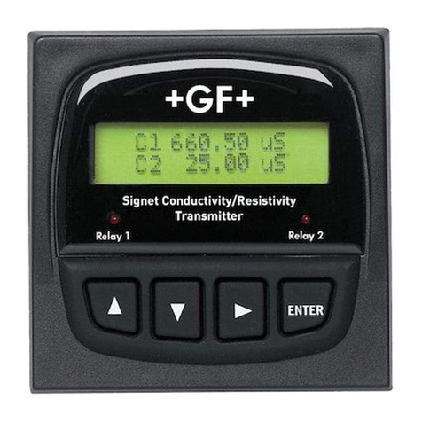
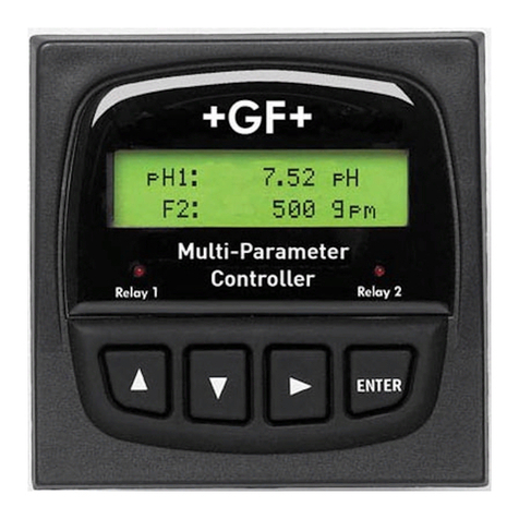
GF Signet 8900 User manual

1
www.gfsignet.com
8900 Multi-Parameter Controller
‡ SIGNET
escription
The 8900 Multi-Parameter Controller takes the
concept of modularity to the extreme. Two
ase units, one with ack-lit LCD and the
other with vacuum fluorescent display can e
configured y the user in the field. Ultimate
flexi ility is achieved via plug-in modules for
either two or four input channels, universal AC
line voltage or 12 to 24 VDC operation, up to
four analog outputs, and up to four relays. The
controller will support up to four additional
relays, for a total of eight, y way of external
System Features
a) 8900 Base Unit: Select ack-lit LCD or
vacuum fluorescent display
) I/O Module: Select 2 or 4 input channels
with or without analog outputs
c) Power Module: Select AC or DC operation
d) Relay Module (optional): Dry-contact or
solid state relays
e) Analog Output Module (optional): Active or
passive 4 to 20mA, or 0 to 5/10 VDC
f) Comm Module (optional): RS232 (pending)
Features
• Modular configurability
• Absolute input versatility
up to four channels
• 1/4 IN enclosure
•S
3L™ digital connectivity
for pH, ORP, conductivity,
level, temperature and
pressure
• Frequency input for
many flow sensor
options
• erived measurements:
ifference, Sum, Ratio,
% Recovery, % Rejection,
% Passage
• Up to four analog
outputs
• Up to eight relays
• RS232 output (pending)
• isplay options
• Plug-in terminals
• Multi-language display
(pending)
Applications
• RO/ I System Control
• Media Filtration
• Pure Water Production
• emineralizers
• Chemical Processing
• Metal & Plastics Finishing
• Fume Scrubbers
• Proportional Chemical
Addition
• Cooling Tower & Boiler
Protection
• Wastewater Treatment
• Aquatic Animal Life
Support Systems
OUT 2 OUT 1
POWER
COMM PORT /
OUT 4 OUT 3
RELAY 2 RELAY 1
RELAY 4 RELAY 3
SENSOR INPUTS
a
d
e
f
c
8900
515
2210 525
2222
2536
2850
2540
7000
2541
2000
2350 2507
2550
2100
2450 2517
2750
7002
2750
Flow
Level
Temp.
Pressure
pH
ORP
Cond.
2450
Compatible Sensors
relay modules. A solute input versatility
allows mixing and matching of up to four
sensors with S3L™ output including pH, ORP,
conductivity/resistivity, pressure, temperature,
and level. Two of the possi le four input
channels may e used for any com ination
of the many +GF+ SIGNET flow sensors with
frequency output. The ta le elow indentifies
sensor models availa le for use with this
controller.
3-8900.099 (A - 2/03)

2www.gfsignet.com
imensions
Installation
DD1
Optional
Rear Cover
Multi-Parameter
C1 23.45 µS/cm
L2 -16.58 ft
Relay 1 Relay 2
ENTER
W
HH2
Units WH
1
H
2
mm
inch
96
3.78
96
3.78
123
4.85
56
2.21
92
3.62
Panel Cutout
92 x 92 mm
(+ 0.8, - 0 mm)
3.6 x 3.6 in.
(+0.031, -0 in.)
Quick-clip
Mounting
Bracket
Gasket on
front side
of panel
Panel Remova le
terminals
OUT 2 OUT 1
POWER
COMM PORT /
OUT 4 OUT 3
RELAY 2 RELAY 1
RELAY 4 RELAY 3
SENSOR INPUTS
C
NO
NC
NO
NC
C
C
N
O
NC
N
O
+
-
+
-
N
LŁ
+
-
BLK
RED
SHLD
BLK
RED
S L
SHLD
BLK
S L
SHLD
+
-
+
-
3
3
AC ONLY
• The front panel provides
NEMA 4X/IP65 protection.
• Standard /4 DIN panel
cutout
• Optional splashproof rear
cover kit with knockout ports
for cable access.
• Several convenient
mounting accessories are
available - see Ordering
Information
Plug-in modules slide into the ase unit
on rails and are then held securely in
place y the rear panel. Changes and
upgrades can e made in the field at
any time.
Panel mounting

3
www.gfsignet.com
Float
Multi-Parameter
C1 23.45 µS/cm
L2 -16.58 ft
Relay 1 Relay 2
ENTER
Float
Multi-Parameter
C1 23.45 µS/cm
L2 -16.58 ft
Relay 1 Relay 2
ENTER
RELAY A RELAY B
+
S
3
L
- +
S
3
L
-
OUTPUT 24VDC
+ -
AC INPUT
‡ SIGNET
Relay Module
DATA
POWER
TEST A
TEST B
Relay A
Relay B
TEST C
TEST D
Relay C
Relay D
INPUT PASS-T RU
L N
RELAY C RELAY D
NC C NO NC C NONC C NO NC C NO
Multi-Parameter
C1 23.45 µS/cm
L2 -16.58 ft
Relay 1 Relay 2
ENTER
Float
FLOW
Wiring Options
Daisy-chain, Multi-drop, or com inations of these with Point-to-point may allow
signifcant savings in total wire and conduit used in installation.
Point-to-Point
(applicable for all sensor types)
Direct wiring of individual
devices to the controller.
Multi- rop:
(S3L™ devices only)
Allows drops from a single
overhead bus. +GF+ SIGNET J-
boxes are very useful in creating
the 3-way junctions that are
necessary in this wiring scheme.
aisy-Chain:
(S3L devices only)
Allows sequential connection
from one device to the next. All
+GF+ SIGNET J-boxes provide
dual conduit ports to simplify this
wiring scheme.
Multi-Parameter
Output1 19.5 mA
Output2 12.3 mA
Relay 1 Relay 2
ENTER
RELAY A RELAY B
+
S
3
L
- +
S
3
L
-
OUTPUT 24VDC
+ -
AC INPUT
Relay Module
DATA
POWER
TEST A
TEST B
Relay A
Relay B
TEST C
TEST D
Relay C
Relay D
INPUT PASS-T RU
L N
RELAY C RELAY D
NC C NO NC C NONC C NO NC C NO
Combination:
The basic wiring options
described above may be
combined to suit specific
installation requirements in
systems containing multiple S3L
devices.

4www.gfsignet.com
Maximum total cable length from S3L™ evices to 8900
Wire Size (AWG)
1 mA 2 mA 4 mA 10 mA 20 mA 40 mA
24 1800 ft 900 ft 450 ft 180 ft 90 ft 40 ft
22 2850 ft 1420 ft 710 ft 280 ft 140 ft 70 ft
20 n/a 2290 ft 1140 ft 450 ft 220 ft 110 ft
18 n/a n/a 1810 ft 720 ft 360 ft 180 ft
16 n/a n/a 2840 ft 1130 ft 560 ft 280 ft
14 n/a n/a n/a 1850 ft 920 ft 460 ft
12 n/a n/a n/a 2940 ft 1470 ft 730 ft
Cable capacitance
must be <30 pf/ft
Cable capacitance must be <50 pf/ft
(practically all cables)
Cable capacitance
must be <15 pf/ft
Total Current Consumption of S3L™ evices
S3L™ evice
Current Consumption per
evice
2210 Level Sensor 10 mA
2222 Level Sensor 10 mA
2350 Temperature Sensor 1 mA
2450 Pressure Sensor 1 mA
2750 p and ORP Sensors 3 mA
2850 Conductivity Sensor 2 mA
8059 External Relay Module * 1 mA
Maximum Current Consumption for S3L™ evices
* The S3L™ communication link between the 8900 and the 8059 is powered by the
8900 and consumes 1 mA maximum. owever, the 8059 External Relay Module
always requires a separate power source for its operation.
Wiring
In order to use this ta le, the total maximum current consumption of all the S3L™ devices
in the system must e known. Refer to the Ca le Length Ta le and add the appropriate
mA values to find the total.
Round up to the nearest column heading in the Ca le Length Ta le a ove or extrapo-
late etween columns to approximate the maximum allowa le ca le length for all S3L
devices in the sytem (regardless of wiring scheme). Notice the influence of wire size
and capacitance on maximum allowa le ca le lengths. Proper ca le selection is
critical, especially when long runs are required in an installation.
• These ta les apply to devices with S3L output only.
• See individual flow sensor data sheets for ca le length limitations.
• See 8900 Instruction Manual for more details.

5
www.gfsignet.com
Rear Terminal View
Specifications
General
Configura ility: Modular (completely
field-commissiona le)
No. of input channels: 2 or 4
Compati le sensors: See Page 1
Input signal types:
•S
3L™: Serial ASCII, TTL level 9600 ps
• Frequency:
0 to 1500 Hz
Accuracy: 0.5% of reading
Measurement types:
Flow, pH, ORP, Conductivity/Resistivity,
Pressure, Temperature, Level,
Derived measurements:
Sum, Difference, Ratio, % Recovery,
% Reject, % Passage
No. of relays supported:
Availa le in pairs: 0, 2, 4, 6 or 8 (Dry-
Contact and/or Solid State)
No. of analog outputs:
Availa le in pairs: 0, 2 or 4 (active and/or
passive 4 to 20mA; and/or 0 to 5/10 VDC)
Enclosure and isplay
Enclosure Rating:
NEMA 4X/IP65 (front face only)
Case material: PBT
Panel Gasket: Silicone Sponge
Window:
Self-healing polyurethane-coated
polycar onate
Keypad:
4- uttons, highly tactile and audi le
Injection-molded silicone ru er seal
Display:
Alphanumeric 2 x 16 ack-lit LCD or
Vacuum Fluorescent (VF) versions
Update rate: 1 second
Accuracy: Sensor dependent
VF Brightness: 4 intensity levels
LCD Contrast: 4 settings
OUT 2 OUT 1
POWER
COMM PORT /
OUT 4 OUT 3
RELAY 2 RELAY 1
RELAY 4 RELAY 3
SENSOR INPUTS
OUT 2 OUT 1
POWER
COMM PORT /
OUT 4 OUT 3
RELAY 2 RELAY 1
RELAY 4 RELAY 3
SENSOR INPUTS
C
N
O
NC
N
O
C
N
O
NC
N
O
+
-
+
-
N
L
+
-
1
2
3
4
5
6
7
8
9
10
11
12
13
14
isplay ranges (see sensor specifications for
actual measurement limits):
• pH: -2.00 to 15.00 pH
• pH Temp.: -40° to 150°C
(-40° to 302°F)
• ORP: -9999 to +9999 mV
• Flow rate:
0.0000 to 999999 units per second,
minute, hour or day
• Totalizer: 0.00 to 99999999 units
• Conductivity:
0.0000to 999990 µS, mS, PPM & PPB
(TDS), kΩ, MΩ
• Cond. Temp.: -99.9° to 250°C
(-148° to 482°F)
• Temperature: -99.9° to 999.9°C
(-148° to 999.9°F)
• Pressure: -99.99 to 9999 psi, kPa, ar
• Level: -99999 to 99999 m, cm, ft, in., %
• Volume: -99999 to 999999 m3, ft3, in3, cm3,
gal, L, kg, l , %
Environmental
Am ient Operating Temperature:
• Back-lit LCD: -10° to 55°C (14° to 131°F)
• VF Display: -10° to 50°C (14° to 122°F)
Storage Temp.: -15° to 80°C (5° to 176°F)
Relative Humidity: 0 to 95%, non-condensing
Maximum Altitude:
2,000m (6,560 ft.)
4,000m (13,123 ft.); use only DC power
supply and, if applica le, solid state relays
to maintain UL safety standard up to this
altitude
Shipping Weights:
• Base unit:
1.0 kg (2.25 l .)
• Power Module:
0.12 kg (0.25 l .)
• I/O Module:
0.12 kg ((0.25 l .)
• Output Module:
0.12 kg (0.25 l .)
• Relay Module:
0.12 kg (0.25 l .)
• RS232 Communication
Module:
0.12 kg (0.25 l .)
3-8900.621C
I/O Module 3-8900.401-X
1
2
3
4
5
6
7
8
9
10
11
12
13
14
+5VDC (Black)
Freq. Input (Red)
GND (Shield)
+5VDC (Black)
Freq. Input 2 (Red)
S L (Red)
GND (White/Shield)
+5VDC (Black)
S L (Red)
GND (White/Shield)
3
3
Analog Output 1
Analog Output 2
(if applicable)
(if applicable)
Frequency
Input
1
Frequency
Input 2
OR
S3L
Input
2
S3L
Input
1
+
-
+
-
I/O Module Terminal
esignation Label
See 8900 Instruction Manual
for wiring detail.

6www.gfsignet.com
Standards
and Approvals
• UL 3101-1
• CSA Standard C22.2
• CE rating for heavy
industry
• Immunity:
EN61326-1
EN61326-2
• Emissions:
EN55011, Class A
and Class B
• Low Votage Directive:
EN61010
• Manufactured under
ISO 9001 and
ISO 14001
Electrical
Power Requirements (AC or DC via Power
Modules)
• Universal AC: 85 to 264 VAC,
50-60 Hz, 24 VA max.
• DC: 9.9 to 26.4 VDC
unregulated, 0.7A max.
Output Power to Sensors:
5VDC up to 40mA total
Terminal type:
Screw-clamp, remova le via plug-in
modules.
Analog Outputs (via I/O Modules and
Output Modules) Any and all analog outputs
are freely assignable to any channel
4 to 20mA Output:
Endpoints are adjusta le and reversi le:
• Minimum default
4.0 mA; user adjusta le from 3.8 to
5.0 mA
• Maximum default
20.00 mA; user adjusta le from
19.0 to 21.0 mA
Test mode:
Produces an adjusta le 4 to 20mA signal
for functional verification of each output
circuit
Isolation:
Up to 48 V AC/DC
Error condition:
22.1 mA (default state when output source
not configured)
Update rate: 100mS
Accuracy:
±32µA over entire operating temperature
range
Resolution: 6µA
Power Supply Rejection: ±1 µA/V
Short circuit and reverse polarity protected
Passive 4 to 20mA
Voltage: 12 to 24VDC ±10%
Max. Impedance: 250Ω @ 12 VDC
500Ω @ 18 VDC
750Ω @ 24 VDC
Active 4 to 20mA
Max. Impedance: 650Ω
0 to 5/10 V C Output:
Output range:
0 to 5 VDC or 0 to 10 VDC, software
selecta le
Endpoints are adjusta le and reversi le:
• Minimum default:
0 VDC; user programma le from 0
to 0.5 VDC
• Maximum default:
5 VDC; user programma le from
4.5 to 5.5 VDC, or 9.5 to 10.5 VDC
Output load: 10kΩ minimum
0 to 5/10 V C Output (continued):
Test mode:
Produces an adjusta le signal for func-
tional verfication of each output circuit
Isolation: Up to 48 V AC/DC
Error condition:
0 VDC (default state when output source
not configured)
Update rate: 100mS
Accuracy:
±20mV over entire operating temperature
range
Resolution: 5mV
Power Supply Rejection: 0.5 mV/V
Relay Modules
Any and all relays are freely assignable to any
channel.
Internal relay modes of operation:
Off, Low, High, Window, Pulse, PWM, USP
External relay modes of operation:
Off, Low, High, Window, USP
Hysterisis: User adjusta le
Time Delay: 0 to 6400 seconds
Solid State Relays
(non-mechanical switches)
Normally open/closed operation:
Software selecta le
Maximum pulse rate:
• 600 pulses/min. (volumetric pulse & PWM
modes)
• 400 pulses/min. (prop. pulse mode)
Maximum voltage rating:
30 VDC or 42 VAC p-p
Current rating:
50mA DC or 50mA AC RMS
On-state impedance: 30Ω or less
Off-state leakage:
400nA or less, AC or DC
Isolation: Up to 48 V AC/DC
Transient protection:
Em edded, up to 48 V over-voltage
ry-contact Relays
(mechanical contacts)
Type: SPDT
Form: C
Maximum pulse rate:
• 600 pulses/min. (volumentric ulse & PWM
modes)
• 400 pulses/min. (prop. pulse mode)
Maximum voltage rating:
30 VDC or 250 VAC
Current rating: 5A
RS232 Communication Module
Connection: Female DB-9
Utilization:
Clone Mode, initially (fully functional
RS232 output is pending)
Specifications (continued)

7
www.gfsignet.com
Ordering Information
Mfr. Part No. Code escription
Base Unit, required; choose one
3-8900 159 000 868 Base unit with ack-lit LCD
3-8900-VF 159 000 869 Base unit with vacuum fluorescent display
I/O Module, required; choose one
3-8900.401-1 159 000 870 Two inputs, no outputs
3-8900.401-2 159 000 871 Two inputs, two passive 4 to 20mA outputs
3-8900.401-3 159 000 872 Two inputs, two active 4 to 20mA outputs
3-8900.401-4 159 000 873 Two inputs, two 0 to 5/10 VDC outputs
3-8900.401-5 159 000 874 Four inputs, no outputs
3-8900.401-6 159 000 875 Four inputs, two passive 4 to 20mA outputs
3-8900.401-7 159 000 876 Four inputs, two active 4 to 20mA outputs
3-8900.401-8 159 000 877 Four inputs, two 0 to 5/10 VDC outputs
Power Module, required; choose one
3-8900.402-1 159 000 878 85 to 264 VAC, 50/60 Hz
3-8900.402-2 159 000 879 12 to 24 VDC, ± 10%
Relay Module, optional; choose zero, one or two
3-8900.403-1 159 000 880 Two dry-contact relays
3-8900.403-2 159 000 881 Two solid-state relays
External Relay Module, optional; choose zero or one
3-8059-2 159 000 770 Two external dry-contact relays
3-8059-2AC 159 000 771 Two external dry-contact relays with power supply
3-8059-4 159 000 772 Four external dry-contact relays
3-8059-4AC 159 000 773 Four external dry-contact relays with power supply
Additional Outputs, optional; choose zero or one
3-8900.405-1 159 000 883 Two passive 4 to 20mA outputs
3-8900.405-2 159 000 884 Two active 4 to 20mA outputs
3-8900.405-3 159 000 885 Two 0 to 5/10 VDC outputs
3-8900.404-1 159 000 882 RS232 communication module
Accessories
Mfr. Part No. Code escription
3-8050-1 159 000 753 Universal Mount Junction Box
3-8050-1CR 159 000 889 Universal Mount Junction Box w/Ranges (for use with 2850)
3-8050-2 159 000 754 Universal Mount Junction Box w/EasyCal (for use with 2750)
3-8050-2CR 159 000 802 Universal Mount Junction Box w/EasyCal (for use with 2850)
3-8050.392 159 000 640 Panel adapter, 1/2 DIN to 1/4 DIN
3-8050.395 159 000 186 Splashproof rear cover
3-8050.396 159 000 617 RC Filter kit (for relay use, 2 pieces)
3-8052-1 159 000 755 3/4 in. NPT Mount Junction Box
3-8052-1CR 159 000 890 3/4 in. NPT Mount Junction Box w/Ranges (for use with 2850)
3-8052-2 159 000 756 3/4 in. NPT Mount Junction Box w/EasyCal (for use with 2750)
3-8052-2CR 159 000 803 3/4 in. NPT Mount Junction Box w/EasyCal (for use with 2850)
3-0000.596-1 159 000 892 1/4 DIN wall mount racket, 6.5 in. (use if no rear cover is installed)
3-0000.596-2 159 000 893 1/4 DIN wall mount racket, 9 in. (use if rear cover is installed)
3-5000.399 198 840 224 Panel adapter, 5 x 5 in. to 1/4 DIN
3-5000.598 198 840 225 Shelf/Pipe mount racket
3-8900.390 159 000 891 DB-9 crossover ca le (for clone mode)
3-9000.392 159 000 368 Liquid tight connector kit, (3 pieces)
3-9000.392-1 159 000 839 Liquid tight connector kit, NPT (1 piece)
3-9000.392-2 159 000 841 Liquid tight connector kit, PG13.5 (1 piece)
7300-7524 159 000 687 24 VDC Power Supply 7.5 W, 300mA
7300-1524 159 000 688 24 VDC Power Supply 15 W, 600mA
7300-3024 159 000 689 24 VDC Power Supply 30 W, 1.3 A
7300-5024 159 000 690 24 VDC Power Supply 50 W, 2.1 A
7300-1024 159 000 691 24 VDC Power Supply 100 W, 4.2 A

8www.gfsignet.com
‡ SIGNET
Signet Scientific Company, 3401 Aerojet Avenue, El Monte, CA 91731-2882 U.S.A. • Tel. (626) 571-2770 • Fax (626) 573-2057
For Worldwide Sales and Service, visit our we site: gfsignet.com • e-mail: [email protected]
Specifications su ject to change without notice. All rights reserved. All corporate names and trademarks stated herein are the property
of their respective companies.
3-8900.099 (A-2/03) © 2003 y Signet Scientific Company printed in U.S.A.
For more information on these products, please contact your local sales company:
AGeorg Fischer Rohrleitungssysteme Gm H, Sandgasse 16, A-3130 Herzogen urg, Tel. 02782/56 43-0, Fax 02782/51 56
AUS George Fischer IPS Pty Ltd., 186-190 Kingsgrove Road, Kingsgrove, NSW 2208, Tel. 02 9554 3977, Fax 02 9502 2561
B/L Georg Fischer N.V./S.A., Digue du Canal 109-111 – Vaartdijk 109-111, B-1070 Bruxelles/Brussel, Tél. 02/556 40 20, Fax 02/524 34 26
BAR George Fischer Ltda Av. dos Nações Unidas, 21689 CEP 04795-100 - S.Paulo - SP Tel.: 155111 247 1311 Fax: 155111 247 6009
CH Georg Fischer Rohrleitungssysteme (Schweiz) AG, Amsler-Laffon-Strasse 1, Postfach, CH-8201 Schaffhausen, Tel. 052/6313026, Fax 052/6312897
Georg Fischer Gm H, Daimlerstraße 6, Postfach 1154, D-73093 Al ershausen, Tel. 07161/302-0, Telex 727867, Fax 07161/30 22 59
K Georg Fischer A/S, Klintehøj Vænge 17, DK-3460 Birkerød, Tel. 42/811975, Fax 42/811622
EGeorg Fischer S.A., Sistemas de tu er´ıas para la industria, Calle Isla de la Palma, 32 – Nave 1, E-28700 San Se astián de los Reyes (Madrid),
Tel. 91/663 80 00, Fax 91/663 81 76
FGeorge Fischer S.A., 105–113, rue Charles Michels, B.P.174, F-93208 Saint-Denis Cedex 1, Tél. 1/49221341, Fax 1/492213 00
GB George Fischer Sales Limited, Paradise Way, Coventry, CV2 2ST, Tel. 01203/53 55 35, Telex 330032, Fax 01203/53 04 50-51
IGiorgio Fischer S.p.A., Via Sondrio 1, I-20063 Cernusco S/N (MI), Agente generale di vendita Tufira S.r.I., Tel. 02/92 18 61, Fax 02/92 14 07 85
JGeorg Fischer Ltd., 2-47, Shikitsuhigashi, 1-chome, Naniwa-ku, Osaka 556, Tel. 6/6482838, Telex 5267785, Fax 6/6482565
NGeorg Fischer A.S, Bygdøy Allé 23, Post oks 3223 Elisen erg, N-0208 Oslo 2, Tel. 22/44 4110, Fax 22/434019
PRC Georg Fischer Piping Systems, Ltd., No. 218 Kang Qiao Dong Road, Pudong Shanghai 201319 Tel. 86 21 58 13 33 33, Fax 86 21 58 13 33 66
RA George Fischer Inc., Lavalle 2614, 1640 Martinez Buenos Aires, Tel. 01/798 74 01, Fax 01/798 40 74
NL Georg Fischer N.V., Lange Veenteweg 19, Post us 35, NL-8160 AA Epe, Tel. 0578678222, Fax 0578621768
S/SF Georg Fischer AB, Box113, S-12523 Älvsjö-Stockholm, Tel. 08/7274700, Fax 08/7492370
SGP George Fischer Pte. Ltd., 15 Kaki Bukit Road 2, KB Warehouse Complex, SGP-417 845 Singapore/Singapore, Tel. 7 47 0611, Fax 7 47 05 77
USA* George Fischer Inc., 2882 Dow Ave., Tustin, CA 92780-7285, Tel. 714/731-8800, Toll Free 800/854-40 90, Fax 714/731-4688,
*Serving North, Central, and South America
Other manuals for 8900
1
Table of contents
Other GF Signet Controllers manuals