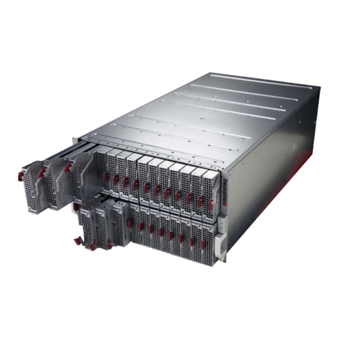
EnerSys alpha SE41-2722 Quick start guide

SE41-2722/2730
Multipurpose Enclosure Series
Technical Guide: 0290002-J0
Effective:07/2020


SE41-2722/2730
Multipurpose Enclosure Series
For technical support, contact Alpha Technologies:
Canada and USA: 1-888-462-7487
International: +1-604-436-5547
Alpha shall not be held liable for any damage or injury involving its enclosures, power
supplies, generators, batteries, or other hardware if used or operated in any manner or
subject to any condition inconsistent with its intended purpose, or if installed or oper-
ated in an unapproved manner, or improperly maintained.
Photographs contained in this manual are for illustrative purposes only. These photo-
graphs may not match your installation.
NOTE:
Operator is cautioned to review the drawings and illustrations contained in this manual
before proceeding. If there are questions regarding the safe operation of this powering
system, contact Alpha Technologies or your nearest Alpha representative.
NOTE:
NOTE:
Copyright
Copyright © 2020 Alpha Technologies Ltd. All rights reserved. Alpha is a registered trademark of Alpha Technologies
Services, Inc.
No part of this documentation shall be reproduced, stored in a retrieval system, translated, transcribed, or transmit-
ted in any form or by any means manual, electric, electronic, electromechanical, chemical, optical, or otherwise
without prior explicit written permission from Alpha Technologies.
This document, the software it describes, and the information and know-how they contain constitute the proprietary,
confidential and valuable trade secret information of Alpha Technologies, and may not be used for any unauthorized
purpose, or disclosed to others without the prior written permission of Alpha Technologies.
The material contained in this document is for information only and is subject to change without notice. While
reasonable efforts have been made in the preparation of this document to assure its accuracy, Alpha Technologies
assumes no liability resulting from errors or omissions in this document, or from the use of the information contained
herein. Alpha Technologies reserves the right to make changes in the product design without reservation and with-
out notification to its users.

0290002-J0 Rev G
2
Table of Contents
1. Safety....................................................................................................................................4
1.1 Safety Symbols.......................................................................................................................... 4
1.2 General Warning and Cautions.................................................................................................. 4
1.3 Electrical Safety......................................................................................................................... 5
1.4 Battery Safety ............................................................................................................................ 5
2. Introduction...........................................................................................................................6
2.1 Product Overview....................................................................................................................... 6
3. Specications........................................................................................................................7
4. Features................................................................................................................................8
4.1 AC and DC Power Options ........................................................................................................ 8
5. Site Evaluation and Pre-Installation......................................................................................9
5.1 Site Selection............................................................................................................................. 9
5.2 Tools Required........................................................................................................................... 9
6. Installation...........................................................................................................................10
6.1 Safety Precautions................................................................................................................... 10
6.2 Plinth Mount Kit for Concrete Pad ........................................................................................... 10
6.3 Wall Mounting the Enclosure ................................................................................................... 12
6.4 Pole Mounting the Enclosure................................................................................................... 13
7. Wiring..................................................................................................................................14
7.1 Grounding the Enclosure......................................................................................................... 14
7.2 AC Input Wiring to the Load Center......................................................................................... 15
8. Maintenance .......................................................................................................................17
8.1 Heat Exchanger Fan Test Procedure....................................................................................... 18
8.2 Heat Exchanger Fan Replacement Procedure........................................................................ 19
8.3 Cooling Fan Test Procedure .................................................................................................... 22
8.4 Cooling Fan Replacement Procedure...................................................................................... 22
9. Warranty Statement and Service Information.....................................................................25
9.1 Technical Support .................................................................................................................... 25

3
0290002-J0 Rev G
9.2 Warranty Statement................................................................................................................. 25
9.3 Product Warranty..................................................................................................................... 25
9.4 Battery Warranty...................................................................................................................... 25
9.5 Warranty Claims....................................................................................................................... 25
9.6 Service Information.................................................................................................................. 25
10. Acronyms and Denitions .................................................................................................26
11. Certication .......................................................................................................................27
List of Figures
Figure 1 — Alpha SE41 Interior View ............................................................................................... 6
Figure 2 — Plinth Template for Mounting Bolts............................................................................... 10
Figure 3 — Preparing Enclosure for Wall Mounting........................................................................ 12
Figure 4 — Bolting the Pole Mount Rail to the Cabinet Brackets ................................................... 13
Figure 5 — Mounting the Bracket/Rail to the Pole.......................................................................... 13
Figure 6 — Enclosure MGB and Chassis Ground.......................................................................... 14
Figure 7 — Main Breaker Load Center Wiring................................................................................ 15
Figure 8 — Main Lug Load Center Wiring ...................................................................................... 15
Figure 9 — Enclosure Alarm Block Wiring...................................................................................... 16

0290002-J0 Rev G
4
1. Safety
SAVE THESE INSTRUCTIONS: This manual contains important safety instructions that must
be followed during the installation, servicing, and maintenance of the product. Keep it in a safe place. Review the
drawings and illustrations contained in this manual before proceeding. If there are any questions regarding the safe
installation or operation of this product, contact Alpha Technologies or the nearest Alpha representative.
1.1 Safety Symbols
To reduce the risk of injury or death, and to ensure the continued safe operation of this product, the following sym-
bols have been placed throughout this manual. Where these symbols appear, use extra care and attention.
The use of ATTENTION indicates specic regulatory/code requirements that may aect the
placement of equipment and /or installation procedures.
WARNING!
WARNING presents safety information to PREVENT INJURY OR DEATH to personnel.
Warnings are indicated by a shock hazard icon, the word WARNING, and a rule beneath
which the information appears.
WARNING!
You must read and understand the following warnings before installing the enclosure
and its component. Failure to do so could result in personal injury or death.
CAUTION!
CAUTION indicates safety information intended to PREVENT DAMAGE to material or equipment.
Cautions are designated with a yellow warning triangle, the word CAUTION, and a rule beneath
which the information appears.
NOTE:
A NOTE provides additional information to help complete a specific task or procedure. Notes
are designated with a checkmark, the word NOTE, and a rule beneath which the information ap-
pears
HOT!
The use of HOT presents safety information to PREVENT BURNS to the technician or
user.
1.2 General Warning and Cautions
• Read and follow all instructions included in this manual.
• Only trained personnel are qualified to install or replace this equipment and its components.
• Use proper lifting techniques whenever handling equipment, parts, or batteries.

5
0290002-J0 Rev G
1.3 Electrical Safety
Before working with any live battery or power system, follow these precautions:
a. Remove all metallic jewelry, such as watches, rings, metal rimmed glasses, or necklaces.
b. Wear safety glasses with side shields at all times during the installation.
c. Use OSHA approved insulated hand tools. Do not rest tools on top of batteries.
WARNING!
Lethal voltages are present within the power system. Always assume that an electrical
connection or conductor is energized. Check the circuit with a voltmeter with respect to the
grounded portion of the enclosure (both AC and DC) before performing any installation or
removal procedure.
WARNING!
Follow battery manufacturer’s safety recommendations when working around battery systems.
Do not smoke or introduce an open flame when batteries (especially vented batteries) are
charging. When charging, batteries vent hydrogen gas, which can explode.
WARNING!
Hazardous voltages and/or energy levels can be present at the input of power systems. The DC
output from rectifiers and batteries, though not dangerous in voltage, has a high short-circuit
current capacity that may cause severe burns and electrical arcing.
• Do not work alone under hazardous conditions.
• A licensed electrician is required to install permanently wired equipment. Input voltages can range up to
240 Vac. Ensure that the utility power is disconnected and locked out before performing any installation or
removal procedure.
• Ensure that no liquids or wet clothes come into contact with internal components.
• Hazardous electrically live parts inside this unit are energized from the batteries even when the AC input
power is disconnected.
• The enclosure which contains the DC or AC power system along with customer installed radios must remain
locked at all times, except when authorized service personnel are present.
• Always assume electrical connections or conductors are live. Turn off all circuit breakers and double-check
with a voltmeter before performing installation or maintenance.
• Place a warning label on the utility panel to warn emergency personnel that a reserve battery source is pres-
ent which will power the loads in a power outage condition or if the AC disconnect breaker is turned off.
• At high ambient temperature conditions, the internal temperature can be hot so use caution when touching
the equipment.
1.4 Battery Safety
• Never transport an enclosure with batteries installed. Batteries must ONLY be installed after the enclosure
has been securely set in place at its permanent installation location. Transporting the unit with batteries in-
stalled may cause a short circuit, fire, explosion, and/or damage to the battery pack, enclosure and installed
equipment.
• Servicing and connection of batteries must be performed by, or under the direct supervision of, personnel
knowledgeable of batteries and the required safety precautions.
• Batteries contain or emit chemicals known to cause cancer and birth defects or other reproductive harm.
Battery post terminals and related accessories contain lead and lead compounds. Wash your hands after
handling batteries.
• Batteries are hazardous to the environment and should be disposed at a recycling facility. Consult the battery
manufacturer for recommended local authorized recyclers.

0290002-J0 Rev G
6
Door mounted fan
Convenience
receptacle
Adjustable 19/23"
equipment rails
(front-to-back)
Insulation
Master Ground
Bar (MGB)
1.2kW rectier shelf
2. Introduction
2.1 Product Overview
The Alpha SE41 is a NEMA 3R multipurpose outdoor enclosure. The SE41 is available with the following options:
• AC, DC, or line power system
• 22" or 30" depth
• Expansion battery enclosure
• Generator inlet and manual transfer switch
• TVSS
• One or two battery trays
• Battery heater mats
• Thermal management options: fan, heat exchanger or air conditioner
• Enclosure heater
Figure 1 — Alpha SE41 Interior View
Battery tray

7
0290002-J0 Rev G
3. Specifications
Table A — Specications
Electrical
AC Input AC load center option: 120/240V, 100A maximum, 60Hz, 1PH, 3W+PE
Generator supply option: 120/240V, 30A maximum, 60Hz, 1PH, 3W+PE
Internal power options: CXRF 48-1.2kW rectier shelf:
CXPS-E3 system:
FXM 650-24:
FXM 650-48:
FXM 1100:
FXM 2000:
120/240V, 57A maximum, 60Hz, 1PH
120/240V, 75A maximum, 60Hz, 1PH
8.7/4.5 @120/230 Vac
10.5 @120 Vac
15.5/8 @120/230 Vac
20/12 @120/230 Vac
Internal cooling options: 2000 BTU air conditioner: 120V, 7A maximum, 60Hz, 1PH
4000 BTU air conditioner: 120V, 13.8A maximum, 60Hz, 1PH
Internal heating options: Enclosure fan heater: 120V, 3.5A maximum, 60Hz, 1PH
Enclosure heater mat: 120V, 1.5A maximum, 60Hz, 1PH
Output DC options: CXRF 48-1.2kW rectier shelf:
CXPS-E3 system:
LPS36 converter shelf:
42-58V (48V nominal), 4.8kW maximum
42-58V, (48V nominal), 14.4kW maximum
±190V, 3.6kW maximum (per shelf)
Convenience receptacle: 120V, 15A, 60Hz, 1PH
UPS: FXM650, FXM1100, FXM2000: 120V, 60Hz, 1PH
Mechanical
Dimensions (H x W x D): SE41-2722 (footprint) 1041mm x 686mm x 559mm (41in x 27in x 22in)
SE41-2730 (footprint) 1041mm x 686mm x 762mm (41in x 27in x 30in)
Weight: Fan Heat
Exchanger 2000BTU Air
Conditioner 4000BTU Air
Conditioner
63.5kg (140lbs) 78kg (172lbs) 87kg (192lbs) 110kg (243lbs)
SE41-2722
SE41-2730 71kg (155lbs) 85kg (187lbs) 94kg (207lbs) 117kg (258lbs)
Mounting: Plinth/Pad/Wall/Pole
Construction / Finish: 5052-H32 aluminum / Powder coat
Insulation: Standard
Equipment rails: 23" adjustable front to back (23" to 19" adapter plates available as option)
Equipment space: 20RU
Cable entrance: Knockouts located on sides, bottom and rear of enclosure
Hinge type: 3-position lift-o hinge
Door prop: Wind-stop with automatic lock
Door latch: 3-point latch with L-handle for padlocking
Installation access: Full front access as well as rear access with a removable gland plate
HVAC
Cooling options: •Thermostat-controlled ltered fan cooling
• 2000 BTU air conditioner
• 4000 BTU air conditioner
• 50W/°C heat exchanger
Heating options: 500W heater integrated with air conditioner
External 400W fan heater
Environmental
Operating temperature: -40 to 46°C (-40 to 115°F)
Storage temperature: -40 to 85°C (-40 to 185°F)
Compliance
NEMA rating: 3R
UPS Products: UL 1778 and CSAC22.2 107.3
DC Products: UL 60950-1 & CSA C22.2 No. 60950-1
Remote Power Feeding: UL 60950-21 & CSA C22.2 No. 60950-21

0290002-J0 Rev G
8
4. Features
4.1 AC and DC Power Options
The following options are available for the SE41-2722 and SE41-2730 enclosure. Contact your representative for
system configuration or part numbers.
Basic Enclosure Options
• SE41-2722; Dimensions: H41" x W27" x D22"
• SE41-2730 Dimensions: H41" x W27" x D30"
Power System Options
• Cordex®HP 48-1.2kW Front Access Rectifier Shelf
• Line Power System; LPS 36
• AC UPS; FXM 650
• AC UPS; FXM 1100
• AC UPS; FXM 2000
Cooling and Heating Options
• Heat Exchanger, 50w / deg C, Thermostat Controlled
• 2000 BTU Air Conditioner
• 4000 BTU Air Conditioner
• Fan Cooled, Thermostat Controlled, MERV 6 Filter
• Heater; 400 Watt AC Powered Heater
AC Input Options
• AC Load Center, 100A 120/240Vac (L-N-L +G) with Main Lug
• AC Load Center, 100A 120/240Vac (L-N-L +G) with 100A 2P Main Circuit Breaker
• Transient Voltage Surge Suppressor: 120/240VAC Split Phase, 40k AIC
• Generator Receptacle: 30A AC Twist Lock, NEMA L14-30, Hubbel HBL2715SW
Battery Trays / Enclosure Options
• One Battery Tray
• Two Battery Tray
• Battery Base with One Battery Tray
Accessories
• Pole Mount Kit
• Wall Mount Kit
• Plinth, 4"
• Concrete Barrier
• Battery Heater Mat

9
0290002-J0 Rev G
5. Site Evaluation and Pre-Installation
5.1 Site Selection
Consider the following before selecting a mounting site:
• The Alpha SE41 enclosure is designed for front and rear access. Only front access is required for maintenance.
• Avoid areas that may be subjected to hot air exhaust from nearby equipment or buildings.
• Find out if your intended area is subjected to architectural controls or environmental restrictions.
• Avoid areas that are prone to flooding
The SE41 outdoor power enclosure has the following mounting options:
• Plinth, mounted on an at-grade concrete slab
• Pole mount
• Wall mount
• Pad mount spacer
• Refer to ordering guide for a list of mounting options and accessories.
5.2 Tools Required
Various insulated tools are essential for the installation. Use this list as a guide:
• Battery lifting apparatus if required
• Electric drill with hammer action, 1/2" capacity
• Various crimping tools and dies to match lugs used in installation
• Load bank of sufficient capacity to load largest rectifier to its current limit
• Digital voltmeter equipped with test leads
• Cable cutters
• Torque wrench: 1/4" drive, 0 - 150 in-lb.
• Torque wrench: 3/8" drive, 0 - 100 ft-lb.
• Insulating canvases as required (2' x 2', 1' x 1', 3' x 3', etc.)
• Various insulated hand tools including:
- Combination wrenches - Ratchet and socket set
- Various screwdrivers - Electricians knife
• Battery safety spill kit required for wet cells:
- Protective clothing - Face shields
- Gloves - Baking soda
- Eye wash equipment
• Cutters and wire strippers (#14 to #22 AWG) [2.5 to 0.34 mm²].

0290002-J0 Rev G
10
6. Installation
Only qualified personnel should install and connect the power components within the Alpha power system. For the
battery installation, refer primarily to the manufacturer’s manual.
6.1 Safety Precautions
Refer to the Safety section near the front of this manual.
6.2 Plinth Mount Kit for Concrete Pad
6.2 .1 Mounting the Plinth to the Concrete Floor
The mounting site must be built in accordance with local building practices and codes to handle the maximum
weight of the enclosure, equipment, and batteries.
Concrete pad installation requiring seismic compliance requires approval by the appropriate engineering discipline,
e.g., civil or structural. Cast-in-place or pre-cast concrete slabs can be used.
Use the template in Figure 2 to place the anchor bolts. Follow the specific recommendations from the fastener
manufacturer to ensure that the securing device achieves its full structural capacity.
2
18
2 23
22
27
4.5 18
3
16
4X 2"
TRADE SIZE
KNOCKOUT
4X
0.625
MOUNTING HOLES
6X 2"
TRADE SIZE
KNOCKOUT
23
27
2
2
2630
3
24
14.5
4.5 18
5.5 16
4X
0.625
MOUNTING HOLES
Figure 2 — Plinth Template for Mounting Bolts
22" Template 30" Template
NOTE:
If using a rubber isolation mat, place the mat onto the pad and orient the mat so the mounting
holes line up. If the rubber mat is ribbed the ribs should sit against the concrete.
1. Place the plinth in position over the anchor holes.
1. Install the anchoring hardware for each anchor FINGER TIGHT.
2. Check that the plinth is level front-to-back and side-to-side.
3. Add shims as needed under one or two of the corners of the plinth, placing the shims as close as possible to the bolts.
4. Once the plinth is level, tighten all bolts to the appropriate torque.
Recommended torque values
1/4" 8.8 ft-lbs
3/8" 32.5 ft-lbs
1/2" 73 ft-lbs

11
0290002-J0 Rev G
6.2.2 Unpacking the Enclosure
CAUTION!
Do not hoist/lift the enclosure with batteries installed.
1. Remove the protective covering from the system. The doors are designed to be locked with a padlock and are
secured with tie-wraps for shipping. Cut the tie-wraps and open the doors.
1. Inspect the packing slip to verify that you have received all the equipment that you ordered.
• All documentation is packed inside the equipment compartment.
• Inspect all moving parts, hardware, connectors, and other equipment.
2. Report any damage to the shipper and Alpha Technologies.
6.2.3 Mounting the Enclosure to the Plinth
1. Unbolt the enclosure from the shipping pallet.
2. Lift the enclosure onto the plinth.
3. Secure the enclosure to the plinth with the four 1/2" x 1-1/4" bolts included with the plinth.
6.2.4 Replacing the Lift Eyebolts
NOTE:
Depending on the internal system configuration, you may need to remove the rear panel to gain
access to the enclosure base rear mounting holes.
Remove the ten security screws and sealing washers of rear panel using a driver and the sup-
plied T-25 security bit.
When reinstalling the rear panel, ensure the panel edge with the gasket that runs the full width
of the panel is located at the top of the rear enclosure opening.
NOTE:
Theft of the eyebolts and solar shield is a common occurrence in some areas. It is recommend-
ed to replace them with stainless steel hex bolts.
1. Remove all four lift eyebolts.
2. Replace with the four 3/8-16 x 1" flange bolts provided with the enclosure.
3. Torque the bolts to a maximum of 32.5 ft-lbs.
Edge with gasket spanning full
width of rear panel

0290002-J0 Rev G
12
6.3 Wall Mounting the Enclosure
The wall mounting brackets facilitate easy mounting to walls. The SE41 enclosure can be mounted to metal or
concrete surfaces. The maximum total weight of the enclosure and equipment must be less than 833lbs.
1. Align the bottom holes in each bracket to the thread holes in the back of the enclosure (Figure 3).
2. Attach the brackets to the enclosure using the hardware in the mounting kit.
NOTE:
Ensure the wall construction can support the bracket and the weight.
Figure 3 — Preparing Enclosure for Wall Mounting
3. Mount horizontally on a vertical surface using fastening hardware that is appropriate for the chosen surface: four
3/8" screws in each bracket.
Recommended torque values
1/4" 8.8 ft-lbs
3/8" 32.5 ft-lbs
1/2" 73 ft-lbs
Use the bottom
pair of holes in
each bracket.

13
0290002-J0 Rev G
6.4 Pole Mounting the Enclosure
Pole mount kits are available in bolt or strap versions. Refer to the order-
ing guide for more information.
6.4.1 Attaching the Brackets to the Rail
1. Bolt the pole mount rail to the cabinet brackets as follows:
a. Orient the top cabinet bracket as shown in Figure 4.
b. Align the holes in the top bracket with the holes in the pole mount rail.
c. Bolt the bracket to the rail with the mounting hardware included with
the bracket. Torque to 32.5 ft-lbs.
2. Repeat for the bottom bracket reversing the orientation of the bracket.
6.4.2 Mounting the SE41 to the Pole - Strapping Method
Note: the bracket can support up to 1500lbs when strapped to the pole.
1. Mount the bracket/rail combination to the pole.
2. Use a total of six bands, two bands at each of the three slot locations on the bracket.
Straps must be stainless or galvanized – see below for specifications.
6.4.4 Mounting the SE41 to the Pole -
Bolt Through Method
Note: the bracket can support up to 1000lbs when
bolted to the pole.
1. Mark drilling locations of the upper and lower
mounting rail bolt-through holes on the utility pole.
2. Drill two 1" holes completely through the pole at
the marked locations.
3. Secure the bracket/rail combination to the pole
with 3/4" threaded rod, washers, and nuts (not
supplied). All hardware must be stainless.
Recommended strapping for
the SE41 pole mount:
• Maximum of two bands at
each of the three slots
• Strap size 3/4" x 0.023",
1,500lbs rating each Strapping location
Bolt-through location
Bolt-through location
Figure 4 — Bolting the Pole Mount Rail to
the Cabinet Brackets
Figure 5 — Mounting the Bracket/Rail to the Pole
6.4.3 Mounting the Cabinet to the Pole
1. Use the lift eyes to raise the cabinet to the pole.
2. Attach the upper and lower bracket to the cabinet with the mounting hardware. Torque to 32.5 ft-lbs.

0290002-J0 Rev G
14
7. Wiring
Only qualified personnel should install and connect the power components. For the battery installation, refer primar-
ily to the manufacturer’s manual.
7.1 Grounding the Enclosure
WARNING!
An enclosure that is not properly grounded presents an electrical hazard.
A proper grounding system that meets or exceeds the specifications of the equipment must be designed and in-
stalled prior to or in conjunction with the construction of the mounting method. The ground system must be bonded
to the enclosure to ensure a “common” or “single-point” ground. Refer to local building codes.
1. Locate the enclosure master ground bar at the front of the enclosure.
NOTE: Chassis ground is connected to the enclosure frame and is terminated at the master ground bar within the
enclosure.
1. Remove a suitable knockout for the external site ground wire connection. The knockouts are located on the
sides, bottom and rear of the enclosure.
2. Route the wire into the enclosure using the appropriate conduit and fittings.
3. Connect the site ground wire to an open position of the enclosure MGB. The master ground bar accepts lugs
with either 1/4" holes on 5/8" centers or 3/8" holes on 1" centers.
Figure 6 — Enclosure MGB and Chassis Ground

15
0290002-J0 Rev G
Figure 7 — Main Breaker Load Center Wiring
Figure 8 — Main Lug Load Center Wiring
7.2 AC Input Wiring to the Load Center
The enclosure AC load center is available with either a main circuit breaker or main lugs. The recommended wire
size is #2 AWG TYP.
Wire Color Connection Terminal
BLACK - Line 1 L1
RED - Line 2 L2
WHITE - Neutral N
GREEN - Ground Protective Earth
L2 L1
N
Protective
Earth
N
Protective
Earth
L1 L2
NOTE:
Service Rating Main Breaker: The main breaker is not provided as a service rated disconnect.
Please check with local codes to see if the unit may be used if a service rating is required.

0290002-J0 Rev G
16
7. 2 .1 Generator Connection (Option)
If equipped, the generator inlet receptacle is located below the AC load center and is wired to the generator circuit
breaker at the factory.
To connect a generator:
1. Connect the generator cable harness to the generator inlet receptacle.
2. Start the generator and allow to stabilize. Refer to the generator manufacturer's instructions.
3. Turn the main breaker on the AC load center to the OFF position.
4. Slide the interlock bracket to release the generator circuit breaker.
5. Turn the generator AC circuit breaker to the ON position.
CAUTION!
When using the generator inlet receptacle, the system loading must be limited to not exceed the
generator supply 30A rated circuit breaker.
Figure 9 — Enclosure Alarm Block Wiring
7.2.2 Power Enclosure Alarm Wiring Block
The alarm wiring block, located on the left side wall in the enclosure, uses Phoenix style blocks. Connect to the local
alarm-sending unit using wire gauges from #28 to #16 AWG (0.08 to 1.31 mm2). Wires do not need to be stripped
when the connections are made.
Refer to drawing 0290002-000-05 at the rear of this manual for the alarm schedule that corresponds to the enclo-
sure HVAC and power systems installed.

17
0290002-J0 Rev G
8. Maintenance
Routine checks and adjustments are recommended to ensure optimum system performance. Qualified service per-
sonnel should conduct.
The following table lists a few maintenance procedures for this system. These procedures should be performed at
least once a year.
Use extreme care when working inside the unit while the system is energized. Do not
make contact with live components or parts.
Circuit cards, including RAM chips, can be damaged by static electricity. Always wear a
grounded wrist strap when handling or installing circuit cards.
Ensure redundant modules or batteries are used to eliminate the threat of service inter-
ruptions while performing maintenance on the system’s alarms and control settings.
WARNING!
Table B — Sample maintenance log
Procedure Date Completed
Clean ventilation openings and rinse out the enclosure lters.
Inspect all system connections. Re-torque if necessary.
Verify alarm/control settings.
Verify alarm relay operation.
Verify HVAC operation
Check for rmware/software updates for the controller and power modules
Table C — Replacement Parts
Parts Part Number Description
Cooling system fan 7400144-001 Fan Assembly, w/Tach & Conn, Te45v2
Cooling system fan thermostat 171-002-10 Thermostat, Small, Bi-Metal, 0 to 60.C, NO
Cooling system GMT fuse
(1.2kW system option) 460-084-10 Fu, Alm Ind (Sprng),5A 125Vac 60VDC
Cooling fan door lter 6480111-001 Filter, Door, Fan Cooled, SE41-2722/2730
AC surge protection device 162-023-10 Surge Suppressor,120/240VAC, 3W, Spt Ph, 50/60Hz
AC surge protection device
circuit breaker 470-294-10 Circuit Breaker, 2 Pole, 15A 120Vac, Plug-on
Battery temperature
compensation probe 747-028-20-071 Temperature Sensor, 1/4" Lug, 6ft Cable Assembly
SE41-2722 battery heater mat 189-304-10 Battery Heater Mat,120Vac 160W,Te25/xh
SE41-2730 battery heater mat 1890056-001 Battery Heater Mat, Silicone, 120Vac, 180W, 20.5x21
Field replacement door 0380588-xxx
(refer to ordering
guide for
options) Assembly, Door, SE41-2722/2730
Air conditioner 171-020-19 2000BTU Air conditioner
Air conditioner 171-024-19 4000BTU Air conditioner

0290002-J0 Rev G
18
8.1 Heat Exchanger Fan Test Procedure
There are six heat exchanger fans. Three inner loop fans are located on the inside of the door and three outer loop
fans on the outside of the door. Perform the following procedure to test the fans.
1. Pull out the plunger of the heat exchanger power door switch.
2. If the fans do not turn on, carefully apply heat to the heat exchanger thermostat using a heat gun. The fans
should turn on above 30°C (86°F). If the fans still do not turn on, check the status of the cooling system breaker
or fuse.
3. Operation of the inner loop fans can be verified through visual inspection.
4. Unplug one of the outer loop fan connectors and listen for a noticeable drop in the sound level of the outside
fans. Plug the fan connector back in.
5. Repeat Step 4 for the two other outer loop fans.
Heat exchanger door switch
Heat exchanger thermostat
Outer loop fan
connectors
This manual suits for next models
1
Table of contents
Other EnerSys Enclosure manuals


