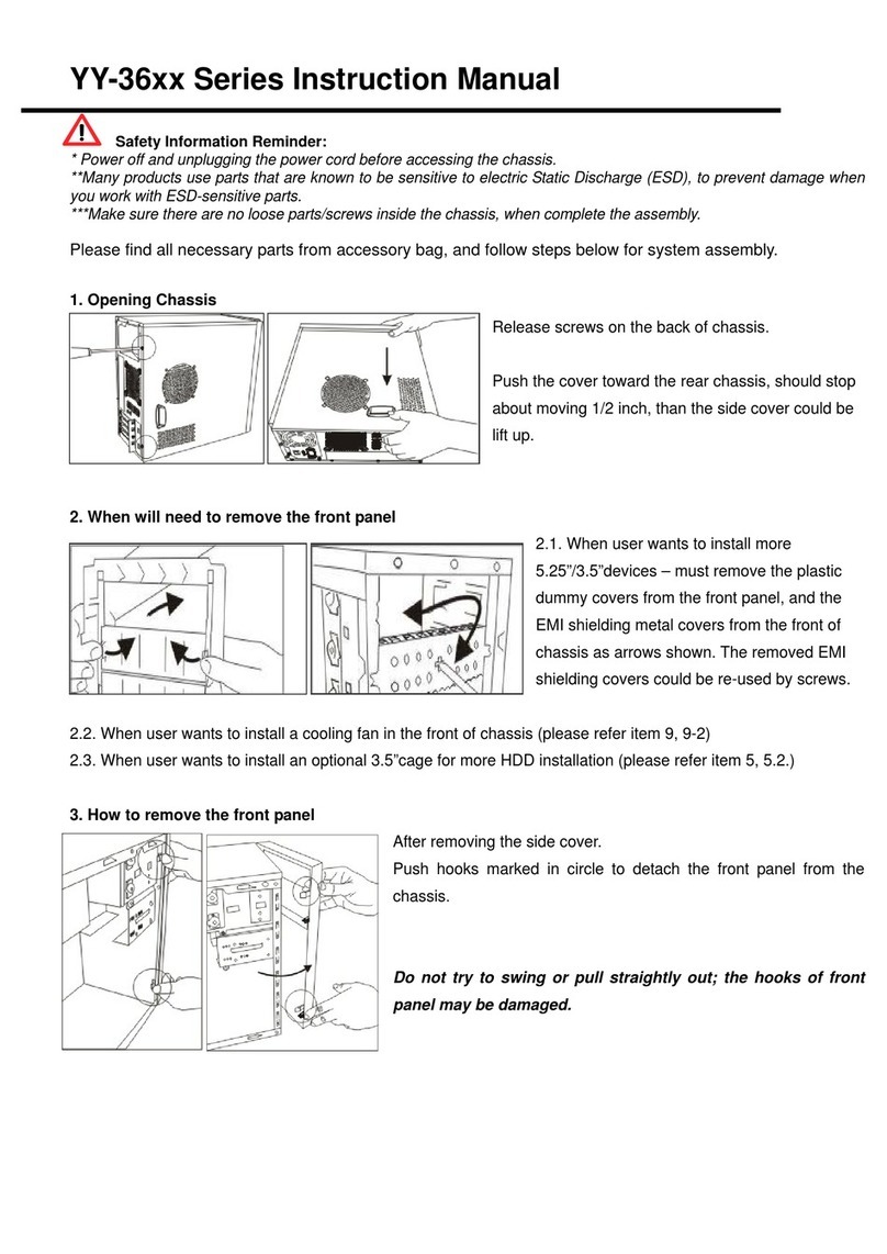
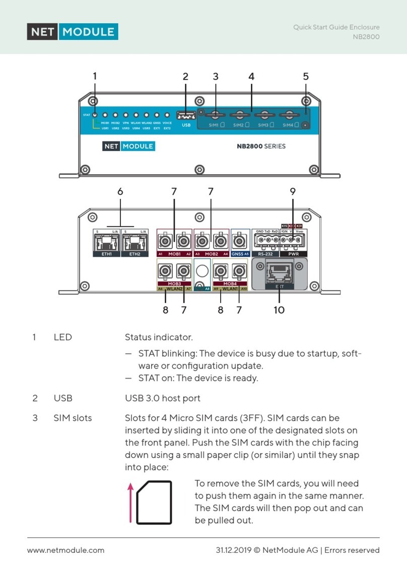
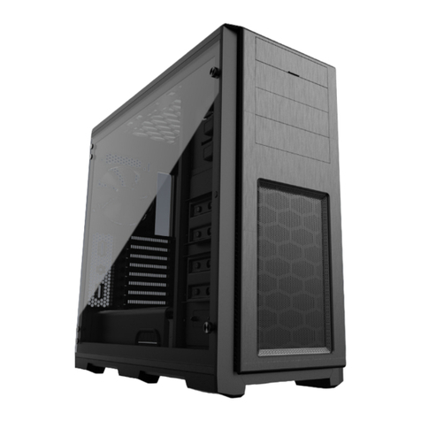
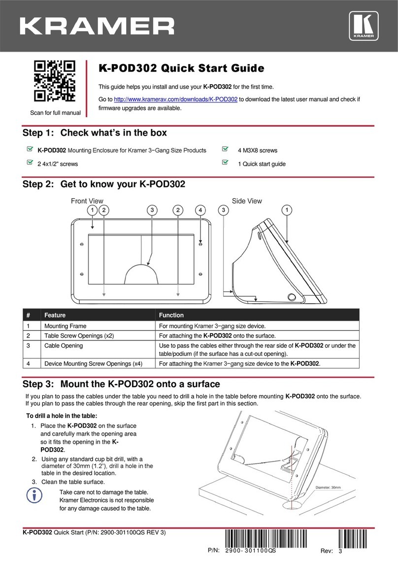
EnerSys Alpha SE48-1616 User manual

SE48-1616, SE48-2216
Outdoor Traffic Enclosure
Technical Guide: 9400030-J0
Effective: 07/2020


SE48-1616, SE48-2216
Outdoor Trac Enclosure
For technical support, contact Alpha Technologies:
Canada and USA: 1-888-462-7487
International: +1-604-436-5547
Copyright
Copyright © 2020 Alpha Technologies Ltd. All rights reserved. Alpha is a registered trademark of Alpha Technologies.
No part of this documentation shall be reproduced, stored in a retrieval system, translated, transcribed, or transmit-
ted in any form or by any means manual, electric, electronic, electromechanical, chemical, optical, or otherwise
without prior explicit written permission from Alpha Technologies.
This document, the software it describes, and the information and know-how they contain constitute the proprietary,
confidential and valuable trade secret information of Alpha Technologies, and may not be used for any unauthorized
purpose, or disclosed to others without the prior written permission of Alpha Technologies.
The material contained in this document is for information only and is subject to change without notice. While
reasonable efforts have been made in the preparation of this document to assure its accuracy, Alpha Technologies
assumes no liability resulting from errors or omissions in this document, or from the use of the information contained
herein. Alpha Technologies reserves the right to make changes in the product design without reservation and with-
out notification to its users.
Alpha shall not be held liable for any damage or injury involving its enclosures, power
supplies, generators, batteries, or other hardware if used or operated in any manner or
subject to any condition inconsistent with its intended purpose, or if installed or oper-
ated in an unapproved manner, or improperly maintained.
Photographs contained in this manual are for illustrative purposes only. These photo-
graphs may not match your installation.
NOTE:
Operator is cautioned to review the drawings and illustrations contained in this manual
before proceeding. If there are questions regarding the safe operation of this powering
system, contact Alpha Technologies or your nearest Alpha representative.
NOTE:
NOTE:


9400030-J0 Rev A
2
Table of Contents
1. Safety������������������������������������������������������������������������������������������������������������������������������������4
1.1 Safety Symbols �������������������������������������������������������������������������������������������������������������������������� 4
1.2 General Warning and Cautions�������������������������������������������������������������������������������������������������� 4
1.3 Electrical Safety ������������������������������������������������������������������������������������������������������������������������� 5
1.4 Battery Safety ���������������������������������������������������������������������������������������������������������������������������� 5
2. Introduction ���������������������������������������������������������������������������������������������������������������������������6
2.1 Product Overview����������������������������������������������������������������������������������������������������������������������� 6
3. Specications������������������������������������������������������������������������������������������������������������������������8
4. Features��������������������������������������������������������������������������������������������������������������������������������9
4.1 AC and DC Power Options �������������������������������������������������������������������������������������������������������� 9
4.2 Ordering Guide �������������������������������������������������������������������������������������������������������������������������� 9
4.3 Related Documents ������������������������������������������������������������������������������������������������������������������� 9
5. Site Evaluation and Pre-Installation������������������������������������������������������������������������������������10
5.1 Site Selection ��������������������������������������������������������������������������������������������������������������������������� 10
5.2 Tools Required ������������������������������������������������������������������������������������������������������������������������� 10
6. Inspection����������������������������������������������������������������������������������������������������������������������������11
6.1 Packing Materials����������������������������������������������������������������������������������������������������������������������11
6.2 Check for Damage ��������������������������������������������������������������������������������������������������������������������11
6.3 General Receipt of Shipment����������������������������������������������������������������������������������������������������11
7. Installation���������������������������������������������������������������������������������������������������������������������������12
7.1 Safety Precautions������������������������������������������������������������������������������������������������������������������� 12
7.2 Mounting the SE48 ������������������������������������������������������������������������������������������������������������������ 12
8. Wiring����������������������������������������������������������������������������������������������������������������������������������16
8.1 Grounding the Enclosure ��������������������������������������������������������������������������������������������������������� 16
8.2 Wiring the SE48 Components�������������������������������������������������������������������������������������������������� 16
9. Operation ����������������������������������������������������������������������������������������������������������������������������17
10. Maintenance ���������������������������������������������������������������������������������������������������������������������18
11. Warranty Statement and Service Information �������������������������������������������������������������������19

39400030-J0 Rev A
11.1 Technical Support������������������������������������������������������������������������������������������������������������������� 19
11.2 Warranty Statement ��������������������������������������������������������������������������������������������������������������� 19
11.3 Product Warranty ������������������������������������������������������������������������������������������������������������������� 19
11.4 Battery Warranty �������������������������������������������������������������������������������������������������������������������� 19
11.5 Warranty Claims��������������������������������������������������������������������������������������������������������������������� 19
11.6 Service Information ���������������������������������������������������������������������������������������������������������������� 19
12. Acronyms and Denitions �������������������������������������������������������������������������������������������������20
13. Certication�����������������������������������������������������������������������������������������������������������������������21

9400030-J0 Rev A
4
1. Safety
SAVE THESE INSTRUCTIONS: This manual contains important safety instructions that must
be followed during the installation, servicing, and maintenance of the product. Keep it in a safe place. Review the
drawings and illustrations contained in this manual before proceeding. If there are any questions regarding the safe
installation or operation of this product, contact Alpha Technologies or the nearest Alpha representative.
1.1 Safety Symbols
To reduce the risk of injury or death, and to ensure the continued safe operation of this product, the following sym-
bols have been placed throughout this manual. Where these symbols appear, use extra care and attention.
The use of ATTENTION indicates specic regulatory/code requirements that may aect the
placement of equipment and /or installation procedures.
WARNING!
WARNING presents safety information to PREVENT INJURY OR DEATH to personnel.
Warnings are indicated by a shock hazard icon, the word WARNING, and a rule beneath
which the information appears.
WARNING!
You must read and understand the following warnings before installing the enclosure
and its component. Failure to do so could result in personal injury or death.
CAUTION!
CAUTION indicates safety information intended to PREVENT DAMAGE to material or equipment.
Cautions are designated with a yellow warning triangle, the word CAUTION, and a rule beneath
which the information appears.
NOTE:
A NOTE provides additional information to help complete a specific task or procedure. Notes
are designated with a checkmark, the word NOTE, and a rule beneath which the information ap-
pears
HOT!
The use of HOT presents safety information to PREVENT BURNS to the technician or
user.
1.2 General Warning and Cautions
• Read and follow all instructions included in this manual.
• Only trained personnel are qualified to install or replace this equipment and its components.
• Use proper lifting techniques whenever handling equipment, parts, or batteries.

59400030-J0 Rev A
1.3 Electrical Safety
Before working with any live battery or power system, follow these precautions:
a. Remove all metallic jewelry, such as watches, rings, metal rimmed glasses, or necklaces.
b. Wear safety glasses with side shields at all times during the installation.
c. Use OSHA approved insulated hand tools. Do not rest tools on top of batteries.
WARNING!
Lethal voltages are present within the power system. Always assume that an electrical
connection or conductor is energized. Check the circuit with a voltmeter with respect to the
grounded portion of the enclosure (both AC and DC) before performing any installation or
removal procedure.
WARNING!
Follow battery manufacturer’s safety recommendations when working around battery systems.
Do not smoke or introduce an open flame when batteries (especially vented batteries) are
charging. When charging, batteries vent hydrogen gas, which can explode.
WARNING!
Hazardous voltages and/or energy levels can be present at the input of power systems. The DC
output from rectifiers and batteries, though not dangerous in voltage, has a high short-circuit
current capacity that may cause severe burns and electrical arcing.
• Do not work alone under hazardous conditions.
• A licensed electrician is required to install permanently wired equipment. Input voltages can range up to
240 Vac. Ensure that the utility power is disconnected and locked out before performing any installation or
removal procedure.
• Ensure that no liquids or wet clothes come into contact with internal components.
• Hazardous electrically live parts inside this unit are energized from the batteries even when the AC input
power is disconnected.
• The enclosure which contains the DC or AC power system along with customer installed radios must remain
locked at all times, except when authorized service personnel are present.
• Always assume electrical connections or conductors are live. Turn off all circuit breakers and double-check
with a voltmeter before performing installation or maintenance.
• Place a warning label on the utility panel to warn emergency personnel that a reserve battery source is pres-
ent which will power the loads in a power outage condition or if the AC disconnect breaker is turned off.
• At high ambient temperature conditions, the internal temperature can be hot so use caution when touching
the equipment.
1.4 Battery Safety
• Never transport an enclosure with batteries installed. Batteries must ONLY be installed after the enclosure
has been securely set in place at its permanent installation location. Transporting the unit with batteries in-
stalled may cause a short circuit, fire, explosion, and/or damage to the battery pack, enclosure and installed
equipment.
• Servicing and connection of batteries must be performed by, or under the direct supervision of, personnel
knowledgeable of batteries and the required safety precautions.
• Batteries contain or emit chemicals known to cause cancer and birth defects or other reproductive harm.
Battery post terminals and related accessories contain lead and lead compounds. Wash your hands after
handling batteries.
• Batteries are hazardous to the environment and should be disposed at a recycling facility. Consult the battery
manufacturer for recommended local authorized recyclers.

9400030-J0 Rev A
6
2. Introduction
2.1 Product Overview
The SE48-1616 and SE48-2216 (hereafter referred to as SE48) is a 6 cubic foot NEMA 3R rated enclosure designed
to protect in outdoor environments.
Door handle
(Stainless steel)
Louvered
Vents
Generator plug
compartment
door
Generator plug
Document
holder
3-point door
latch
Upper
battery
shelf
19" equipment
rack
Lower
battery
shelf Door prop
two-positions
Air filter installed
at door louvers
Figure 1 — Alpha SE48 Front and Side View
Figure 2 — Alpha SE48 Interior View

79400030-J0 Rev A
Figure 3 — Slide-out Battery Shelf Detail
Press to
close shelf
Lift to
open shelf

9400030-J0 Rev A
8
3. Specifications
Table A — Specications - SE48
Electrical
DC Fan: 48Vdc, 100CFM or better. Thermostat controlled.
Internal Fluorescent Lamp:120Vac, 9W (optional)
On Battery Lamp: 48Vdc LED (optional)
Generator Plug: NEMA L5-30P (optional)
Manual Transfer Switch: 250V, 40A (optional)
Mechanical
Enclosure type: Outdoor NEMA 3R
Dimensions (H x W x D): SE48-1616: (footprint) 1220mm x 419mm x 419mm (48in x 16.5in x 16.5in)
SE48-2216: (footprint) 1220mm x 559mm x 419mm (48in x 22in x 16.5in)
Weight (empty): SE48-1616: 34kg (75lbs)
SE48-2216: 38kg (84lbs)
Mounting: Side/Base/Pedestal/Pole
Construction: 1/8" thick 5052-H32 aluminum
Finish: Bare aluminum nish (optional: gray)
Equipment rack:
Horizontal 19" rack mount rails, EIA spacing, 8 RU wide (SE48-1616), 11 RU (SE48-2216)
Battery shelves: Two battery shelves:
• Fixed weld-on upper battery shelf
• Removable lower battery shelf for accessing service wire and mounting holes
• Battery Slide Out Tray (option on SE48-2216)
Ventilation: • Louvered vents at door and vent slots at top front
• Air inlet lter install at door louvers, xed in all three dimensions
• Air lter size: 9.75" (W) x 8.0" (H) x 0.875" (thick)
• Air lter type: re-usable and washable
• Bug screen inside vent slots at top
Door: • Latch: 3-point latch with #2 Corbin slam latch integrated with the handle
• Handle: stainless steel, trac light industry standard
• Prop: 1/4" bare aluminum rod, two positions. Holes located in tab mounted at
the front of bottom pan providing 90° and 150° door holding positions
• Hinge: stainless steel piano hinge, reverse swaged, 1.5" (W), 0.075" (thick),
0.188" Dia. pin, 0.500" knuckles
• Document holder on inside door
HVAC
Cooling: Thermostat-controlled ltered 48VDC fan, 100CFM or better; thermostat turns fan
on at 49°C (120°F) and turns fan o at 32°C (90°F).
Environmental
Operating temperature: -40 to 46°C (-40 to 115°F)
Storage temperature: -40 to 85°C (-40 to 185°F)
Compliance
NEMA rating: 3R
CSA: C22.2 No. 94.1-07 Enclosures for Electrical Equipment, Non-Environmental
Considerations
C22.2 No. 94.2-07 Enclosures for Electrical Equipment, Environmental
Considerations
UL UL 50 – Enclosures for Electrical Equipment, Non-Environmental Considerations
UL 50 E – Enclosures for Electrical Equipment, Environmental Considerations

99400030-J0 Rev A
4. Features
4.1 AC and DC Power Options
The following power options are available with the SE48:
• FXM 650
• FXM 1100/2000
4.2 Ordering Guide
Refer to ordering guide for a complete list of part numbers for the different mounting options and accessories.
4.3 Related Documents
FXM UPS Operator’s Manual (Doc# 017-230-B0)
Universal Automatic Transfer Switch/Universal Generator Transfer Switch Installation Manual (Doc# 020-165-B0)
Local electrical codes (e.g. National Electrical Code, or NFPA 70 in the United States, Canadian Electrical Code or
CSA C22.1 in Canada)

9400030-J0 Rev A
10
5. Site Evaluation and Pre-Installation
5.1 Site Selection
Consider the following before selecting a mounting site:
• Avoid areas that may be subjected to hot air exhaust from nearby equipment or buildings.
• Find out if your intended area is subjected to architectural controls or environmental restrictions.
• Avoid areas that are prone to flooding
The SE48 outdoor power enclosure has been designed for the following mounting options:
• Side mount to an existing enclosure
• Stand alone on a concrete pad
• Stand alone on pedestal kit
• Pole mount to either a wooden or steel/concrete pole
• Refer to ordering guide for a complete list of part numbers for the different mounting option accessories.
5.2 Tools Required
Various insulated tools are essential for the installation. Use this list as a guide:
• Electric drill with hammer action, 1/2" capacity
• Various crimping tools and dies to match lugs used in installation
• Load bank of sufficient capacity
• Digital voltmeter equipped with test leads
• Cable cutters
• Torque wrench: 1/4" drive, 0 - 150 in-lb.
• Torque wrench: 3/8" drive, 0 - 100 ft-lb.
• Various insulated hand tools including:
- Combination wrenches - Ratchet and socket set
- Various screwdrivers - Electricians knife
• Battery safety spill kit required for wet cells only:
- Protective clothing - Face shields
- Gloves - Baking soda
- Eye wash equipment
• Cutters and wire strippers (#14 to #22 AWG) [2.5 to 0.34 mm²].

119400030-J0 Rev A
6. Inspection
6.1 Packing Materials
Alpha is committed to providing products and services that meet our customers’ needs and expectations in a sus-
tainable manner, while complying with all relevant regulatory requirements. As such Alpha strives to follow our quality
and environmental objectives from product supply and development through to the packaging for our products.
Rectifiers and batteries are shipped on individual pallets and are packaged according to the manufacturer’s guide-
lines.
Almost all of Alpha’s packaging material is from sustainable resources and/or is recyclable. See the following table
for the material and its environmental codes.
Cardboard Polyethylene
Terephthalate
Low Density
Polyethylene
Polystyrene Steel Aluminum Wood
Packing boxes
Caps
Flexible film
Packaging
Bubble wrap
Shrink wrap
Plastic bags
Foam Strapping on
pallets
Strapping on
pallets
Pallets
Lumber
6.1.1 Returns for Service
Save the original shipping container. If the product needs to be returned for service, it should be packaged in its
original shipping container. If the original container is unavailable, make sure that the product is packed with at least
three inches of shock-absorbing material to prevent shipping damage.
Alpha Technologies is not responsible for damage caused by improper packaging of returned products.
6.2 Check for Damage
Before unpacking the product, note any damage to the shipping container. Unpack the product and inspect the
exterior for damage. If any damage is observed, contact the carrier immediately.
Continue the inspection for any internal damage. In the unlikely event of internal damage, inform the carrier and con-
tact Alpha Technologies for advice on the impact of any damage.
6.3 General Receipt of Shipment
The inventory included with your shipment depends on the options you have ordered. The options are clearly
marked on the shipping container labels and bill of materials.
Call Alpha Technologies if you have any questions before you proceed: 1 888 462-7487.

9400030-J0 Rev A
12
7. Installation
Only qualified personnel should install and connect the power components within the Alpha power system.
7.1 Safety Precautions
Refer to the Safety section near the front of this manual.
7.2 Mounting the SE48
The SE48 can be mounted in one of the four following ways:
1. Side Mount to an existing enclosure such as a traffic light cabinet. Mounting holes must be drilled on site and
mounted with six sets of 1/4"-20 18-8 stainless steel hex head bolts and nuts assembly (supplied).
2. Stand-alone using 4 x 1" knock outs for base mount to concrete pad with 3/4" screw anchors (not supplied).
See Figure 4 for mounting pad hole patterns.
3. Stand-alone using 4 x 1/2" knock outs for mounting to optional pedestal kit with 3/8" screws (supplied in pedes-
tal kit). See Figure 4 for mounting pad hole patterns.
4. Pole mount to either a wooden or steel/concrete pole, using the optional pole mount kit. Holes must be drilled
on site and the mounting kit attached with the supplied hardware.
Figure 4 — Mounting Pad Hole Patterns
7. 2 .1 Mounting the Enclosure to a Pole
If you are mounting the enclosure to a wood, steel/concrete pole, requires two optional pole mount strap kits. Install
these to the rear panel of the enclosure according to the following instructions.
Installing the pole mount strap kit
Pole mount strap kit includes:
• Two pole mount straps
• Eight sets of 1/4-20 x 3/4" S/S carriage bolts
• 1/4" S/S flat washers and 1/4" S/S locknuts
• One 3/8-16 x 1" cap screw
8 RACK UNITS
2 RACK UNITS 5.00" DEEP
WITH GEN PORT ONLY
31.26
25.98
32.21
3
3
4
5
6
7
8
D
C
B
A
C
B
MOUNTING PAD HOLE PATTERN
- 1" DIA KNOCK-OUT
MOUNTING PAD HOLE PATTERN
- 0.50" DIA KNOCK-OUT
SHELF WITH
RACK MOUNT RAIL
A A
1.75
10.00
15.94
6.00
16.00
6.75
3.56
10.00
O 1.00 KO 4PL
O .50 KO 4PL
6.75
14.063
.000
2.98
14.25
25.51
44.27
18.31 REF
O 3.00 EKO
WIRE ENTRANCE
NOTE:
To get access to the mounting pad holes, remove the lower battery shelf by undoing four screws
on the shelf.

139400030-J0 Rev A
To install the strap kit:
1. Drill through the eight indent marks using a 9/32" drill bit.
Note: These are not knockouts. Do not attempt to punch them out.
2. Secure the two pole mount straps to the enclosure with the supplied carriage bolts, nuts and flat
washers.
Drill holes
through indent
marks.
1/4-20 x 3/4" S/S
Carriage Bolt 4PL
1/4" S/S Locknut 4PL Pole Mount Strap
1/4" S/S Flat Washer 4PL

9400030-J0 Rev A
14
3. Install the 3/8-16 x 1" cap screw loosely into the bottom pole mount strap. Do not tighten until after the enclosure
has been seated onto the pole/wall mounting brackets.
Mounting the Enclosure to a Wooden Pole
Tools required:
• Auger or drill for boring 3/4" diameter holes in the wooden pole
• Assorted sockets or wrenches
Materials required:
• Two wood pole mount brackets (provided in the kit)
• Two 5/8" diameter machine bolts (UNC threaded), SAE (Grade 5 or better), length to suit pole
• Two 5/8" diameter zinc-plated flat washers
• Two 5/8" diameter hex nuts (UNC threaded)
To mount enclosure to wooden pole:
1. Install the two pole mount straps on the rear panel of the enclosure. Refer to the instructions given on page 13.
2. Mark drilling locations for the upper and lower mounting brackets on the utility pole. Use a plumb line to check
for plumbness. Centers should be 37.00" apart.
3. Drill two 3/4" diameter holes completely through the pole at the marked locations.
4. Secure each bracket to the pole with a 5/8" machine bolt, washer and nut (to be supplied by the installer). Do
not fully tighten the bolts at this time.
5. Lower the enclosure onto the upper and lower mounting brackets.
6. Tighten the machine bolts to secure the enclosure to the pole.
WARNING!
It is recommended to position the enclosure on the opposite side of the pole from oncoming traffic
to reduce the danger of falling equipment in the event that a pole is struck by an automobile.
37.00 in
Wood Pole / Wall Mount
Brackets
5/8" Hardware
(not supplied)

159400030-J0 Rev A
7. Tighten the cap screw at the lower pole mount strap to secure the enclosure to the pole mount bracket.
Mounting the Enclosure to a Steel or Concrete Pole
Tools required:
• Assorted sockets or wrenches
Materials required:
• Two steel/concrete pole mount brackets (provided in the kit)
• Two steel bands (to be supplied by the installer, rated to support the loaded enclosure and sized for the pole
diameter)
To mount enclosure to steel or concrete pole:
1. Install the two pole mount straps on the rear panel of the
enclosure. Refer to the instructions given on page 13.
2. Mark the locations for the upper and lower mounting brackets on
the utility pole. Use a plumb line to check for plumbness. Centers
should be 37.00" apart.
3. Attach the mounting brackets to the pole at the marked locations
using the steel bands. Do not fully tighten the steel bands at this
time.
4. Lower the enclosure onto the upper and lower mounting
brackets.
5. Tighten the machine bolts to secure the enclosure to the pole.
6. Tighten the cap screw at the lower pole mount strap to secure
the enclosure to the pole mount bracket.
Secure enclosure with
3/8-16 bolt provided
Lower enclosure
onto brackets
WARNING!
It is recommended to position the enclosure on the opposite side of the pole from oncoming traffic
to reduce the danger of falling equipment in the event that a pole is struck by an automobile.
37.00 in
Steel Pole Mount
Brackets Steel bands
(not supplied)

9400030-J0 Rev A
16
8. Wiring
Only qualified personnel should install and connect the power components within the Alpha power system. For the
battery installation, refer primarily to the manufacturer’s manual.
The SE48 with Generator Plug compartment option, when ordered with UATS/UGTS Accessory Shelf, should have
the generator transfer switch pre-wired. Refer to the wiring of the UATS/UGTS Manual Transfer Plate in the Installa-
tion chapter of the UATS/UGTS Installation Manual if necessary. See Related Documents on page 9.
The SE48, regardless of which Generator Plug option is chosen, is ready for wiring once the UPS and/or the UATS/
UGTS Accessory Shelf is installed. Refer to the UPS and the UATS/UGTS manuals for wiring details. See Related
Documents on page 9.
8.1 Grounding the Enclosure
WARNING!
An enclosure that is not properly grounded presents an electrical hazard.
A proper grounding system that meets or exceeds the specifications of the equipment must be designed and in-
stalled prior to or in conjunction with the construction of the mounting pad. The ground system must be bonded to
the enclosure to ensure a “common” or “single-point” ground. Refer to local building codes.
1. Locate the enclosure master ground bar at the left front of the enclosure.
NOTE: Chassis ground is connected to the enclosure frame and is terminated at the master ground bar within the
enclosure.
1. Remove a suitable knockout for the external site ground wire connection. The knockouts are located on the
sides, bottom and rear of the enclosure.
2. Route the wire into the enclosure using the appropriate conduit and fittings.
3. Connect the site ground wire to an open position of the enclosure SE48. The master ground bar accepts lugs
with either 1/4" holes on 5/8" centers or 3/8" holes on 1" centers.
If you have the factory installed UATS/UGTS Accessory Shelf, you can also install additional accessories. Although
you can customize the placement of accessories in the UATS/UGTS Accessory Shelf, Alpha recommends the
preferred factory-installed configurations described in the UATS/UGTS Installation Manual.
8.2 Wiring the SE48 Components
8.2 .1 Thermostat controlled 48 VDC Fan
1. Connect the black (common) wire of the DC fan to the center (common) terminal of the connector.
2. Connect the red (positive) wire to the left terminal.
3. Plug the connector into dry contact C6 on the Alpha FXM UPS.
NOTE:
If you have a 24Vdc FXM system which require a 24 Vdc fan, please contact Technical Support.

179400030-J0 Rev A
9.2 .1 On Battery Lamp (48 VDC) (optional on some models)
This optional lamp turns on when the UPS is operating in the battery backup mode (inverter mode). Connect the
lamp wiring to dry contact C8 on the Alpha FXM UPS as shown below.
9.2.2 Door Ajar Switch (optional on some models)
The switch closes when the door is opened. It is used to trigger one of the user programmable inputs of the Alpha
FXM UPS (typically C7 is used) and program the input as an Intrusion Alarm. See the Alpha FXM UPS Operator’s
Manual for details
9.2.3 Internal Lamp with Light Switch (120VAC) (optional on some models)
Connect to the terminal block marked “Lamp” in the Receptacle plate of the UATS/UGTS Accessory Shelf. See
UATS/UGTS manual for details.
CAUTION!
The dry contact C8 can only be used for Alpha specified accessories
9. Operation
Operation of the SE48 is determined by the final installed configuration in the end system for the intended applica-
tion. Please refer to the applicable equipment product manuals listed in Related Documents on page 9.
This manual suits for next models
1
Table of contents
Other EnerSys Enclosure manuals


