7
7.1 –Información de maniobras y clase / Information about cycles and class
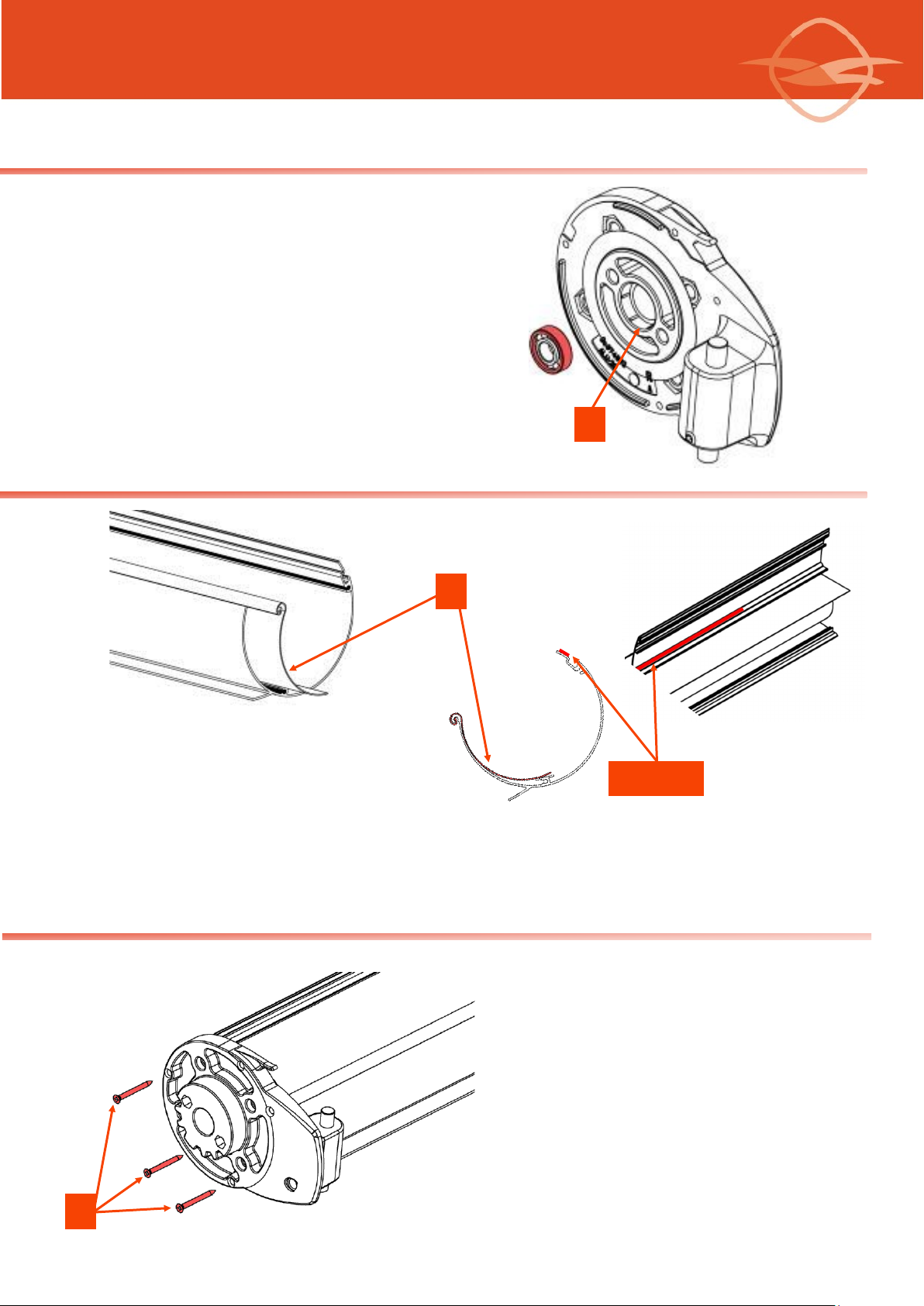
Los brazos llevan una banda protectora de colores para su idencación:
VERDE: Visto desde fuera, lado derecho
ROJA: Visto desde fuera, lado izquierdo
NUNCA EXTRAER LAS BANDAS DE SEGURIDAD PARA LA TENSIÓN HASTA HABER SUJETADO EL BRAZO AL PERFIL DE CARGA.
NEVER EXTRACT THE SAFETY TENSION BANDS UNTIL THE ARM HAS BEEN FIXED TO THE FRONT PROFILE.
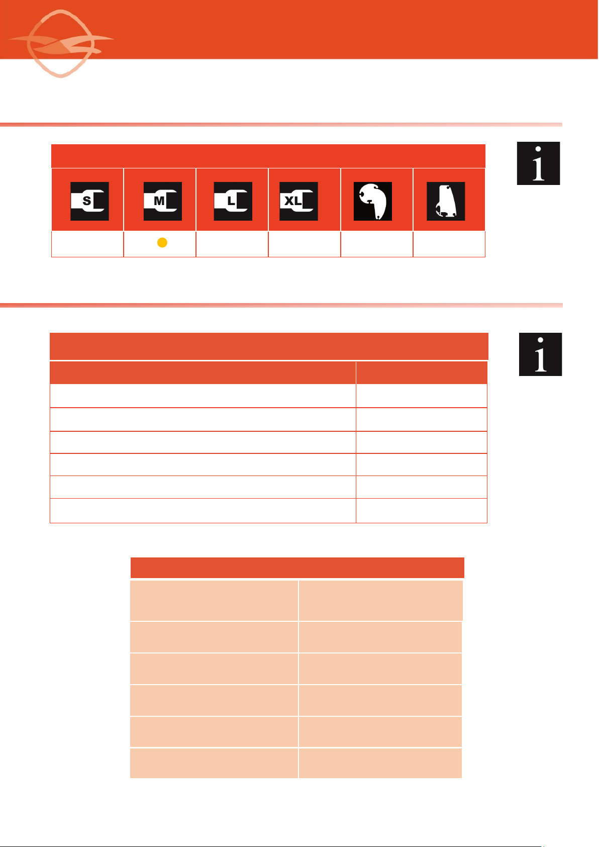
6.1 –Clasificación según norma Europea / Classification according to European standards : EN 13.561:2015
Salida brazo / Arm projecon (m) Línea / Width Clase / Class
4,00 6,00 C.1
The arms have a protecve band for correct idencaon:
GREEN: Right hand side viewed from outside
RED: Le hand side viewed from outside
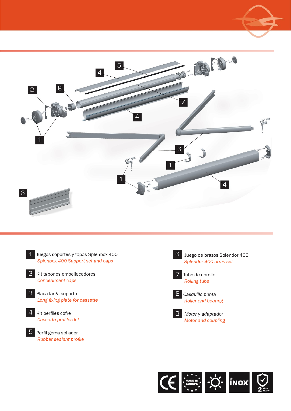
SPLENBOX 400
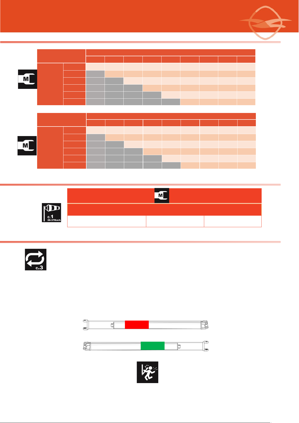
5.1- Tablas de selección motor / Selection motor table
Tubo enrolle Ø70 /
Ø70 Rolling tube
Linea / Width (m)
2,00 2,50 3,00 3,50 4,00 4,50 5,00 5,50 6,00
Salida /
Projecon
(m)
1,50 30 30 30 30 30 30 30 30 30
2,00 30 30 30 30 30 30 30 30
2,50 35 35 35 35 35 35 35
3,00 35 35 40 40 40 40
3,50 40 40 40 40 50
4,00 50 50 50 50
Tubo enrolle Ø80 /
Ø80 Rolling tube
Linea / Width (m)
2,00 2,50 3,00 3,50 4,00 4,50 5,00 5,50 6,00
Salida /
Projecon
(m)
1,50 30 30 30 30 30 30 30 30 30
2,00 30 35 35 35 35 35 35 35
2,50 40 40 40 40 40 40 40
3,00 50 50 50 50 50 50
3,50 50 50 50 50 50
4,00 50 50 50 50