Hobo S-WCG-M003 User manual

Ultrasonic Wind Speed and Direction Smart Sensor
(S-WCG-M003) Manual
22408-B
The Ultrasonic Wind Speed and Direction smart sensor is designed to work with HOBO®
stations and is powered by its own built-in solar panel. The smart sensor has a plug-in modular
connector that allows it to be added easily to a HOBO station. All sensor parameters are stored
inside the smart sensor, which automatically communicates configuration information to the
logger without the need for any programming or extensive setup. Note: This sensor has been
modified to work with Onset station loggers only.
Specifications
Wind Speed/Gust Wind Direction
Measurement Range 0 to 41.16 m/s (0 to 92.07 mph) 0 to 359 degrees
Accuracy ±0.8 m/s (1.79 mph) or ±4% of
reading, whichever is greater
0.2 to 3 m/s (0.44–6.7 mph):
±4 degrees
>3 m/s (6.7 mph): ±2 degrees
Resolution 0.4 m/s (0.89 mph) 1 degrees (0 to 359 degrees)
Measurement Definition Wind speed readings are taken
every three seconds for the
duration of the logging interval
Wind speed: Average speed for
the entire logging interval
Gust speed: The highest three-
second wind recorded during
the logging interval
See Measurement Operation.
Unit vector averaging used;
vector components for each
wind measurement are
calculated every three seconds
for duration of logging interval
(see Measurement Operation)
Operating Temperature Range
Without Icing
-15°C to 55°C (5°F to 131°F)
Environmental Rating Weatherproof
Housing Polyacetal
Dimensions Sensor length: 380 mm (14.96 inches)
Sensor head diameter: 60 mm (2.36 inches)
Sensor rod diameter: 16 mm (0.63 inches)
W
eight 200 g (7 oz)
Power Supply Photovoltaic panel, LIFEP04 3.2 V -600 mAh battery
Bits per Sample 8 for each channel, 24 total
Number of Data Channels* 3
Measurement Averaging
Option
Automatic averaging (see Measurement Operation)
Cable Length Available 3 m (9.8 ft)
Length of Smart Sensor
Network Cable*
0.5 m (1.6 ft)
The CE Marking identifies this product as complying with all relevant
directives in the European Union (EU).
* A single HOBO station can accommodate 15 data channels and up to 100 m (328 ft) of smart sensor cable (the digital
communications portion of the sensor cables).
Ultrasonic Wind Speed &
Direction Smart Sensor
S-WCG-M003
Items included:
•North alignment tool
•U-bolts with hex nuts,
brackets, spacers, and lock
nuts for mounting on a
mast or cross arm
Items required:
•Phillips-head screw driver
•10 mm wrench (if
mounting on a mast or
cross arm)
•Screws and drill (if
mounting on a vertical
surface)
Accessories:
•Grounding kit (M-GKA)

Ultrasonic Wind Speed and Direction Smart Sensor (S-WCG-M003) Manual
1-800-LOGGERS 2 www.onsetcomp.com
Connecting the Sensor Battery
The smart sensor includes a factory-installed battery that has
been disconnected for shipping. When connected, this
rechargeable battery is charged by the solar panel on the top of
the sensor head. Follow these instructions for connecting the
battery.
Important: It is recommended that you only connect the
battery when you are ready to deploy the sensor because it will
require regular, direct sunlight to remain charged. Once the
battery is connected, it will lose its charge after 10 days if it
does not receive any sunlight.
To connect the sensor battery:
1. Connect the two battery cables.
2. Insert the connected battery cables into the sensor rod
tube.
3. Once the cables are fully inserted, push and twist the cap
into place at the end of the sensor rod.
The cap should be fully seated in the sensor rod without
any gaps as shown below. If there is a gap, remove the cap
and push the battery cables further in the sensor rod to
make more room for the cap.
4. Slide the sensor rod up so that the bottom is flush with the
bottom of the sensor base. Loosely tighten the four screws
to keep the sensor rod in place.
Once these steps are complete, mount the sensor using the
guidelines in the next section.
Mounting
Mounting Guidelines
Use the following guidelines to determine the best location for
installing the sensor.
•The sensor can be damaged with improper handling. Store
the sensor in its shipping box until you are ready to install it.
•Mount the sensor in the sunlight within 10 days of
connecting the battery to prevent it from losing all charge.
•Choose a location free of turbulence and magnetic fields
resulting from electricity, engines, radio transmitters,
radars, etc.
•For the most accurate readings, the sensor should be
mounted 3 m (9.8 ft) or more above the ground and 10 m
(32.8 ft) away from nearby objects.
•When mounting the sensor on a roof, the sensor must be
mounted at a height equal to the building’s length or five
times the building’s height. Install the sensor in the middle
of the roof when possible. You may do this by mounting
the sensor on an Onset tripod or mast, or a metal pipe. It is
not recommended to install the sensor on a slanted roof
Battery cables unconnected
Battery cables
connected
Battery cables
being inserted
into sensor rod
Push this cap into
sensor rod end
Cap fully seated
in sensor rod
Sensor rod flush
with bottom of
sensor base

Ultrasonic Wind Speed and Direction Smart Sensor (S-WCG-M003) Manual
1-800-LOGGERS 3 www.onsetcomp.com
because it can generate upwards turbulence that will
affect the sensor measurements.
•You may mount the sensor on a wooden post.
•Mount the sensor in a location that receives direct sunlight
for several hours a day to ensure the built-in solar panel is
charged regularly. Make sure the sensor is positioned in
the sun and not under the forest canopy or obstructions.
•The sensor must be aligned to true north when mounted
to ensure accurate wind direction readings. Use the
alignment tool as described North Alignment.
•If the sensor is mounted on the same mast as a rain gauge,
mount the wind sensor away from the rain gauge on a half
cross arm (M-CAB) so that the wind sensor does not
interfere with rainfall measurements. If there is no rain
gauge on the same mast, mount the wind sensor directly
to the top of the mast.
•The tripod or mounting mast must be properly grounded.
For field installations, you can use Onset’s Grounding Kit
(M-GKA).
•If the station is deployed in an area subject to frequent
thunderstorms, installing a lightning rod nearby can
reduce the risk of damage.
•To minimize measurement errors due to ambient RF, keep
the sensor cable as far as possible from other cables
carrying high frequency or high-current signals.
•After the sensor is mounted on a mast, secure the smart
sensor adapter to the mast with the cable ties as shown.
Multiple smart sensor adapters can be stacked as shown
in the example below on the right.
Alternatively, mount the smart sensor adapter to a flat
surface using two screws (no larger than a #6) and two
washers as shown in the example below.
•Secure the sensor cable with cable clips or weather
resistant cable ties to protect it from damage in the wind.
Place clips or cable ties approximately every 1 to 1.6 m (3
to 5 ft). Do not use metal staples to secure the cable as
they can cut the cable.
•Secure the mast that the sensor is mounted on so that it
does not vibrate. If you are using an Onset mast or tripod,
secure it with guy wires.
Mounting on a Mast
Follow these instructions for mounting the sensor on a tripod
or mast. The mounting U-bolts included can be used for
mounting the sensor on a mast or tripod with an outside
diameter ranging from 35–48 mm (1.38–1.89 inches).
1. Connect the battery if you haven’t already done so (see
Connecting the Sensor Battery).
2. Place the mounting U-bolt around the mast and slide the
bracket over the threaded U-bolt ends as shown in this
example. Make sure the flat part of the bracket is facing
out.
3. Repeat step 2 with the other U-bolt and bracket.
4. Insert the ends of the U-bolts through the four holes in the
square sensor base at the bottom of the sensor rod. Loosely
install the hex nuts on the four bolt ends with a 10 mm
wrench.
Smart sensor
adapter secured
with cable ties
One of four hex nuts
installed
Mounting base at
the bottom of the
sensor
One Smart Sensor
Adapter Mounted Mounting
U-bolts
around
mast
Two Smart Sensor
Adapters Stacked
and Mounted
Mounting
bracket
Mounting
bracket
Mounting
bracket, flat
side facing out

Ultrasonic Wind Speed and Direction Smart Sensor (S-WCG-M003) Manual
1-800-LOGGERS 4 www.onsetcomp.com
5. Raise the sensor to the desired height on the mast.
6. Use the wrench to tighten the hex nuts until the sensor is
firmly fastened on the mast. Do not overtighten the hex
nuts.
7. Follow the steps in North Alignment to make sure the
sensor is pointed to true north.
Mounting on a Tripod Cross Arm
Follow these instructions for mounting the sensor on a cross
arm.
1. Attach the cross arm to the mast before installing the
sensor.
2. Connect the battery if you haven’t already done so (see
Connecting the Sensor Battery).
3. Use a 10 mm wrench to install two hex nuts at the base of
the threaded end of the U-bolts as shown. Tighten the hex
nuts all the way down to the end of the threads. Repeat
with the other U-bolt.
4. Insert the threaded bolt end through the hole in the bracket
so that the bracket rests on top of the hex nut with the flat
end facing out. Place a spacer on top of the bracket as
shown below. Repeat for the other threaded bolt end and
for both ends of the other U-bolt.
5. Insert both bolt assemblies through the bottom of the
mounting base and secure with finger-tightened lock nuts.
6. Slide the assembly above over the end of the cross arm as
shown below. Make sure the hole in the cross arm is
centered on the sensor mounting base as shown.
7. Make sure the cross arm is flush against the top spacer. The
spacer and threaded bolts should be flush against the top of
the bracket holes. Tighten the locknuts with a wrench. Do
not overtighten them.
Inserted cross arm
Hole in
cross arm
must be
positioned
as shown
U-bolt assemblies inserted
through holes on mounting
base on sensor rod
Area where cross arm will
be inserted in next step
Spacers flush
against top of
holes
Finger-
tighten
these
lock
nuts
Hex nuts installed at bottom
of threaded end of bolts
Bracket on top of hex nut,
flat side facing out
Spacer on bracket
Cross arm
flush against
top spacer
Spacer and
threaded bolts
at top of
bracket holes

Ultrasonic Wind Speed and Direction Smart Sensor (S-WCG-M003) Manual
1-800-LOGGERS 5 www.onsetcomp.com
8. Follow the steps in North Alignment to make sure the
sensor is pointed to true north.
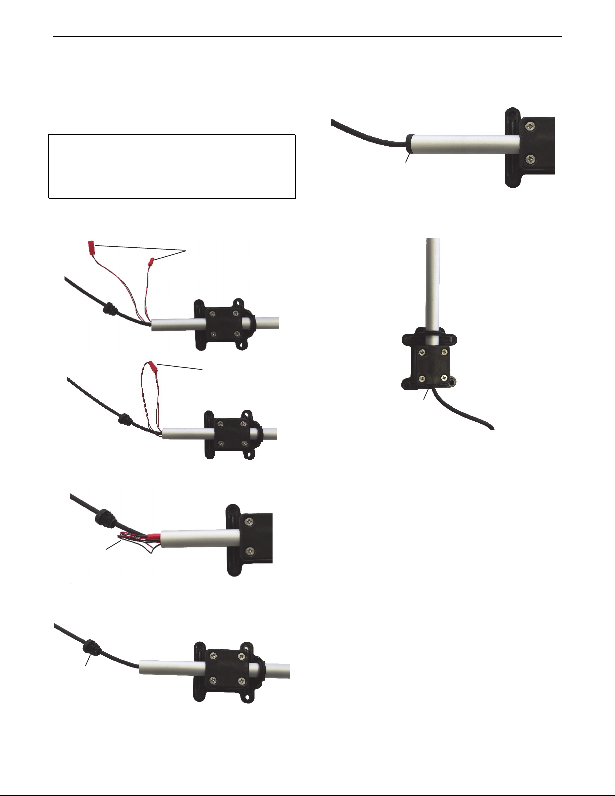
Mounting on a Vertical Surface
Follow these instructions for mounting the sensor on a wooden
post or vertical surface with user-supplied screws.
1. Connect the battery if you haven’t already done so (see
Connecting the Sensor Battery).
2. Hold the sensor rod base against the surface where you will
be mounting the sensor and use a pencil to mark the
location of the four screw holes on the base.
3. Use a drill with a 5 mm (3/16 inch) drill bit to make pilot
holes in these locations.
4. Drive four lag screws with a maximum diameter of 6 mm
(0.24 inches) through the holes in the sensor base and into
the mounting surface.
5. Follow the steps in North Alignment to make sure the
sensor is pointed to true north.
North Alignment
The sensor must be oriented to true north to obtain meaningful
wind direction data.
Tools required:
•Alignment tool (included)
•GPS or compass
•Flag, cone, or other temporary marker
•Phillips-head screwdriver
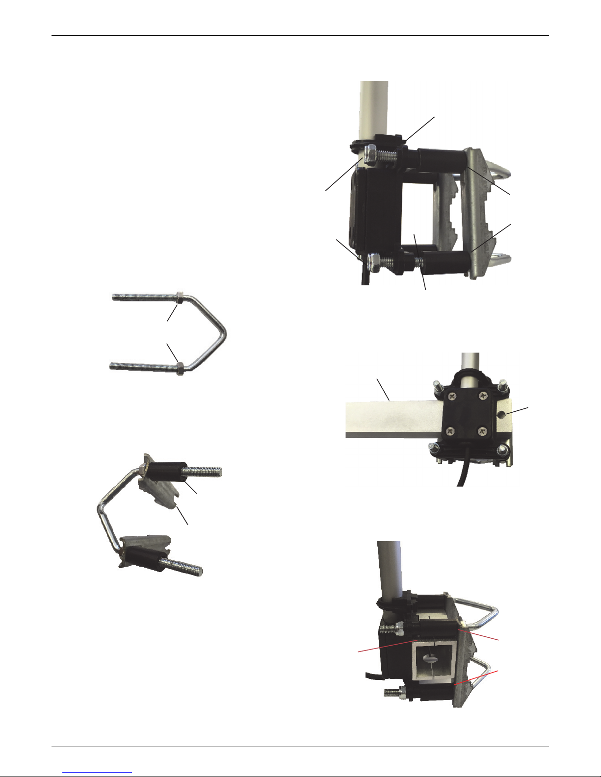
1. Use a Phillips-head screwdriver to slightly loosen the four
screws on the sensor rod mounting base so that the sensor
rod can be adjusted. (If the rod already moves freely, you
do not need to loosen the screws any further.)
2. Clip the alignment tool on the sensor tube and slide it so
that it snaps into the dedicated slots. Do not tamper with
the slots. The tool must gently find its place.
3. Using your GPS or a magnetic compass, go to a point that is
directly north of the station and at least 100 m (328 ft)
away from the station. To determine this point, move until
the station is directly south of you.
•Compass instructions:
a. Get the declination angle for your location to align the
sensor to true north. Worldwide declination information
is available at https://www.ngdc.noaa.gov/geomag-
web/#declination.
b. Go about 100 m (328 ft) to the north of the station with
a marker (e.g. flag or orange cone) and compass.
c. Using the compass, move to where the station is due
south of you and determine true north by doing the
following:
•If there is a west declination, move due west from
your position until the station is east by the
declination angle from magnetic south.
•If there is an east declination, move due east from
your position until the station is west by the
declination angle from magnetic south.
d. Place your marker where you are standing (this is true
north).
•GPS instructions: Establish a waypoint with the handheld
GPS receiver. You may want to use averaging to minimize
the waypoint position error if your GPS receiver is so
equipped. (For best results, the estimated position error
of the waypoint should be less than 10 feet if the
distance to the sensor is 100 meters, and less than 20
feet for a distance of 200 meters.) Mark the waypoint
with a flag, orange cone, or other suitable marker. Walk
back to the sensor and determine the bearing to the
waypoint you just created with the GPS receiver. Again
you may need to determine the average value of the
bearing to keep the errors to a minimum.
Loosen the four
screws on the
mounting base
(shown on
cross arm in
this example)
Alignment tool
clipped in place

Ultrasonic Wind Speed and Direction Smart Sensor (S-WCG-M003) Manual
1-800-LOGGERS 6 www.onsetcomp.com
4. Use the alignment tool to align the sensor so it is pointing
north.
5. Once the sensor is aligned to north, tighten the screws and
remove the alignment tool.
Maintenance
The sensor does not normally require any maintenance other
than an occasional cleaning. Use a clean soft cloth with mild
soap and fresh water. Do not use alcohol-based cleaning
products.
Connecting the Sensor to a Station
To connect the sensor to a station, stop the station from
logging and insert the smart sensor’s modular jack into an
available smart sensor port on the station. See the station
manual for details on operating stations with smart sensors.
Measurement Operation
Wind direction measurements are averaged over the logging
interval or a 3-second timeframe (whichever is greater). If you
set up the sensor to log faster than every 3 seconds, the same
sensor reading will be recorded until a new 3-second average is
calculated. For example, if the sensor is logging at a 1-second
interval, the sensor will report the same wind direction (its
calculated average) for three samples before calculating and
reporting a new value for another three samples. Measurement
averaging for this sensor is independent of the logger’s
measurement averaging. Therefore the automatic
measurement averaging for this sensor is not affected by any
sampling intervals entered for averaging on other sensors.
Direction Averaging
Unit vector averaging is used to determine wind direction
because traditional averaging would produce inaccurate
results. For example, three measurements of 350, 11, and 12
degrees—which are all winds from the north—averaged
together would result in 126 degrees, which incorrectly
indicates a southeasterly wind. Instead, the vector components
(North/South and East/West) for each wind measurement are
calculated every three seconds for the duration of the logging
interval. At the conclusion of the logging interval, the
North/South and East/West components are averaged and
then re-combined to calculate the average wind direction for
the logging interval.
Verifying Sensor Accuracy
It is recommended that you check the accuracy of the sensor
annually. The sensor cannot be calibrated. If the smart sensor is
not providing accurate data, then it is damaged.
Replacing the Battery
The sensor uses a LIFEPO4 3.2 V – 600 battery (HRB-WCG) to
charge the built-in solar panel on the top of the sensor. If
HOBOware® or HOBOlink® is consistently reporting wind speed
and gust speed readings of zero and wind direction at 178.3
degrees in error, then the battery likely needs to be replaced.
To replace the battery:
1. Remove the sensor from the mounting location.
2. Remove the cap from the bottom of the sensor rod and
disconnect the battery cables.
3. Mark the underside of the sensor head where the north
alignment marking is located for easier reattachment later.
4. Using a Phillips-head screwdriver, unscrew the three
sensors (two of which are shown in the previous photo) to
detach the sensor head from the tube.
5. Slide the sensor rod away from the sensor top and gently
pull the battery and its cables completely out of the sensor
tube.
Mark the
sensor head
where the
north marking
is located
Disconnect the battery
cables
Cap removed
from sensor
rod
Remove the battery
and the battery cables
from the sensor rod

Ultrasonic Wind Speed and Direction Smart Sensor (S-WCG-M003) Manual
1-800-LOGGERS (564-4377) • 508-759-9500
www.onsetcomp.com/support/contact
© 2018 Onset Computer Corporation. All rights reserved. Onset, HOBO, HOBOware, and HOBOlink are
trademarks or registered trademarks of Onset Computer Corporation. Some material reprinted with
permission from LCJ Capteurs. All other trademarks are the property of their respective companies.
22408-B
6. Feed the cables for the new battery into the sensor rod
until they come out at the other end. Use needle-nose
plyers if necessary to gently pull the cables through the
bottom end.
7. Place the new battery inside the top of the sensor rod as
shown.
8. Gently push the wires inside the sensor rod so that you can
easily reattach the sensor head.
9. Make sure the mark from step 3 is aligned with the north
marking and reattach the sensor head. Tighten the three
screws.
10. Connect the battery and insert the battery cables into the
bottom end of the sensor rod. Reinsert the cap at the end
of the rod. See Connecting the Sensor Battery for details.
11. Redeploy the sensor.
WARNING: Do not cut open, incinerate, heat above 85°C
(185°F), or recharge the battery. The battery may explode if the
logger is exposed to extreme heat or conditions that could
damage or destroy the battery case. Do not dispose of the
logger or battery in fire. Do not expose the contents of the
battery to water. Dispose of the battery according to local
regulations for lithium batteries.
Pull these cables and connectors out
through the end of the sensor rod
Place battery
inside the case
Cables inserted into sensor rod,
ready to reattach sensor head
Table of contents
Other Hobo Accessories manuals

Hobo
Hobo RX User manual

Hobo
Hobo RXW-WCF Series User manual

Hobo
Hobo RXW series User manual

Hobo
Hobo S-LIA-M003 User manual

Hobo
Hobo S-LIA-M003 User manual

Hobo
Hobo S-LWA-M003 User manual

Hobo
Hobo RX3000 Series User manual

Hobo
Hobo S-LIA-M003 User manual

Hobo
Hobo WELL-CAP-02 User manual

Hobo
Hobo RXW-GP3 Series User manual

Hobo
Hobo RXW-UC Series User manual

Hobo
Hobo RXW-SPER Series User manual

Hobo
Hobo S-RGx-M002 User manual

Hobo
Hobo HOBOnet RXW-THC-B Series User manual

Hobo
Hobo Davis S-RGE-M002 User manual

Hobo
Hobo RXW-THC Series User manual

Hobo
Hobo RXW 10HS User manual

Hobo
Hobo RXW-THC-B Series User manual

Hobo
Hobo RXW TEROS-12 User manual