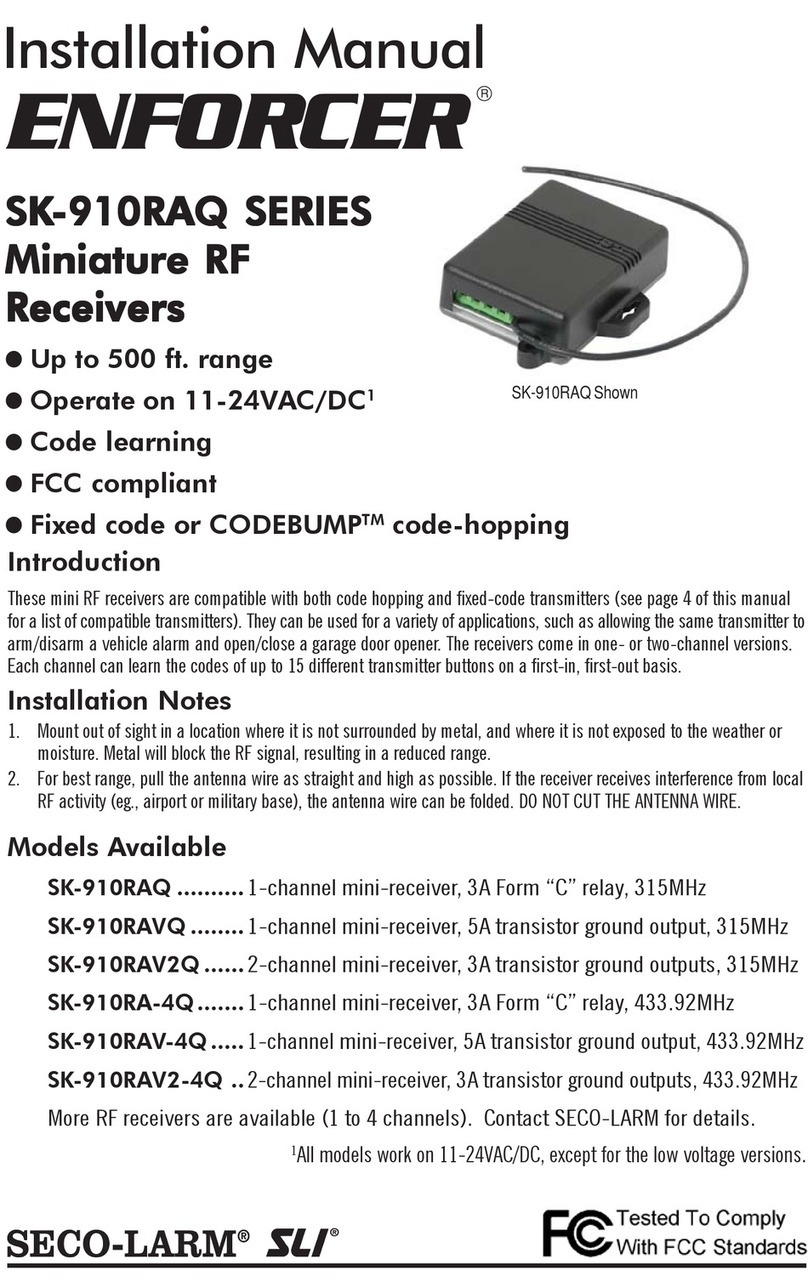
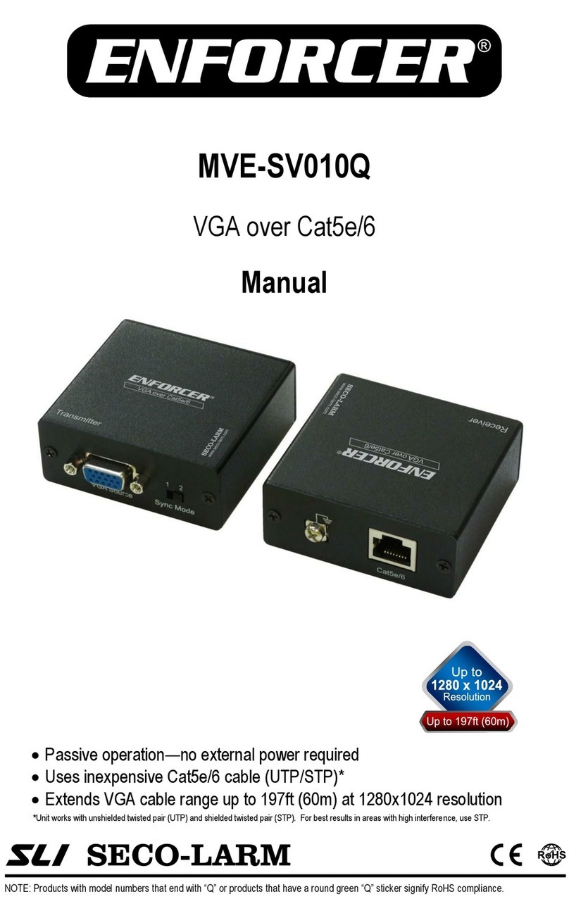
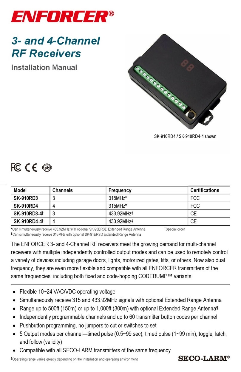
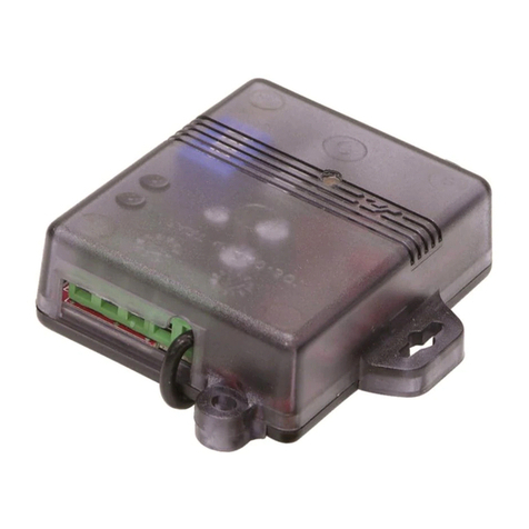
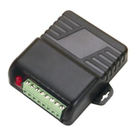
ENFORCER SK-910RQ User manual

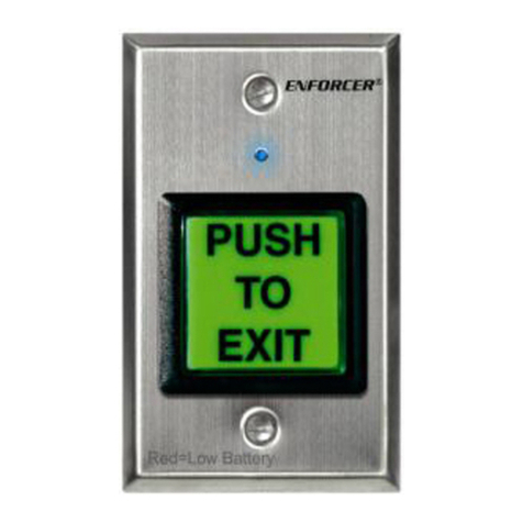
ENFORCER Wireless Request-to-Exit Plates
4 SECO-LARM U.S.A., Inc.
HOW TO CODE THE TRANSMITTER
1. Remove the small screw from the back of the case. Open the case and remove the PCB
(printed circuit board). Locate the row of 1 DIP switches (see Fig. 1)
2. Select a code. Each transmitter code consists of five digits (from 1~9, not ). For this
illustration, we will use 25679 as an example.
3. Each digit of the 5-digit code will be set with two DIP switches and each DIP switch has 3
positions (-, o, and +). The DIP switches are numbered 1~1 from left to right. (see Fig.1).
4. Therefore, the first digit of the transmitter code is set with DIP switches 1 and 2, the second
digit is set with DIP switches 3 and 4, and so on.
5. To program the transmitter code, adjust the position of the DIP switches using the DIP switch
sequences shown in the Coding Guide Chart (Table 1, below). So, to program the first digit to be
'2,' set DIP switches 1 and 2 to the positions shown under the digit '2' in the Coding Guide Chart
(i.e. DIP switch 1 to '+' and DIP switch 2 to '-'). Repeat with DIP switches 3 and 4 for the second
digit, etc.
Table 1: Coding Guide Chart
Digit
1
2
3
4
5
6
7
8
9
DIP
Switch
Position
6. For example, to program the code 25679, the DIP switches should be adjusted as shown below.
7. Replace the PCB into the case and reattach the back of the case.
Notice: The changes or modifications not expressly approved by the party responsible for compliance could void
the user’s authority to operate the equipment.
IMPORTANT NOTE: To comply with the FCC RF exposure compliance requirements, no change to the antenna or
the device is permitted. Any change to the antenna or the device could result in the device exceeding the RF
exposure requirements and void user’s authority to operate the device.
THIS DEVICE COMPLIES WITH PART 15 OF THE FCC RULES. OPERATION IS SUBJECT TO THE FOLLOWING TWO CONDITIONS:
(1) THIS DEVICE MAY NOT CAUSE HARMFUL INTERFERENCE AND (2) THIS DEVICE MUST ACCEPT ANY INTERFERENCE
RECEIVED, INCLUDING INTERFERENCE THAT MAY CAUSE UNDESIRED OPERATION.
PITSW1
SK-919TT1S-BUQ_
FCC manual_150609.doc
1
2
3
4
5
6
7
8
9 1
+
O
-
+
O
-
+
O
-
+
O
-
+
O
-
+
O
-
+
O
-
+
O
-
+
O
-
+
O
-
1st
2nd
3rd
4th
5th
–
-
digits
︷
︷
︷
︷
︷
1
2
3
4
5
6
7
8
9 1
+
O
-
Factory preset code
-
55555
1st
2nd
3rd
4th
5th
–
-
digits
in code
︷
︷
︷
︷
︷
Fig
ure
1
NOTE: Products with a model number that ends with “Q” or have a round green “Q” sticker represent RoHs compliant products.
ENFORCER
®
MANUAL
SK-910RQ / SK-919TT1S-BUQ
System:
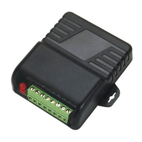
These RF receivers are compatible with both code hopping and fixed-code transmitters. They can be used for
a variety of applications, such as allowing the same transmitter to arm/disarm a vehicle alarm and open/close
a garage door opener. The receivers come in one- or two-channel versions. Each channel can learn the codes
of up to 15 different transmitter buttons on a first-in, first-out basis.
The ENFORCER Weatherproof Transmitter Box receives trigger input from sensors and other devices, and
sends a wireless signal to the SK-91 RQ or other receiving device.
Feat res:
• Weatherproof Transmitter Box:
-
Weatherproof IP65.
-
Dual power: Battery or external 12VDC.
-
Over 68 billion possible codes.
-
Onboard power saving features.
-
Compact size.
•RF Receiver:
-
Powered by 11VDC ~ 24VDC or 11VAC ~
24VAC
-
Range up to 25 feet. 315MHz
-
Memory Capacity: 15 transmitter button codes per
channel
-
Relay Contact Rating: Form ‘C’ type; 1 A @
24VDC or 12 VAC per channel
Installation:
1. Mount the receiver out of sight in a location where it is not surrounded by metal, and where it is not
exposed to the weather or moisture. Metal will block the RF signal, resulting in a reduced range.
2. For best range, pull the antenna wire of the receiver as long and straight as possible. If the receiver
receives interference from local RF activity (e.g.., airport or military base), the antenna wire can be folded.
DO NOT CUT THE ANTENNA WIRE.
3. For installation of the Weatherproof Transmitter Box please see page 4.
NOTE: Do not ho se the transmitter in a metal box, this will greatly red ce the range.
4. Test the operation of the Weatherproof Transmitter Box in the location where it will be installed.
NOTE: The Weatherproof Transmitter Box first needs to be programmed into the receiver before
testing. See learning proced re.
5. Check and make sure the battery or external power source is securely connected.
SECO-LARM
®

ENFORCER Wireless Request-to-Exit Plates
2 SECO-LARM U.S.A., Inc.
Learning a New B tton Code into Receiver (channel 1)
1. Press receiver mode switch #1 for three seconds. The green LED will start to flash quickly.
2. While the green LED is flashing quickly, press Weatherproof Transmitter Box test switch. The green LED
will flash once and then turn off to show that that button was learned.
NOTE — The green LED will flash a maximum of 15 seconds. If no transmitter button is pressed during this
time, the receiver will exit the code-learning mode, and the green LED will turn off.
Learning a New B tton Code into Receiver (channel 2)
The procedure is the same as for channel 1, except mode switch #2 initiates the code-learning process, and
the red LED shows status.
Note Regarding Code Learning
1. The receiver will only learn the code of a particular button once. Once a button’s code is learned, if you try
to code-learn that button again, whether it is for the same channel or not, the receiver will exit code
learning mode.
2. Each channel can learn the codes of a maximum of 15 transmitter codes. If you attempt to learn a
sixteenth button, the earliest code learned will be deleted.
3. To clear all codes — Press the appropriate mode switch (#1 or #2) for three seconds. When the LED
starts flashing, press that switch again for three seconds. The LED flashes twice to indicate that all codes
associated with that channel are now deleted.
Receiver Programming Relay O tp t Modes
The relay output(s) can be programmed for one of four different modes, depending on the
application:
• 4-second momentary — Press the transmitter button once. The relay turns on for 4 seconds,
and then turns off. (This is the DEFAULT mode)
• 1-second momentary — Press the transmitter button once. The relay turns on for 1 second,
and then turns off.
• Toggle — Press the transmitter button once, and the relay turns on. Press a compatible
transmitter button again, and the relay turns off.
• Validity — The relay turns on for as long as the transmitter button is pressed.
To program outputs, open case and
find the 2 jumpers marked LP1 and
LP2. Cut these jumpers, if needed, as
follows:
O tp t type LP1 LP2
4-second momentary Uncut Uncut
1-second momentary Uncut Cut
Toggle Cut Uncut
Validity Cut Cut
NOTE — On the 2-channel models,
the output mode of both relays is the
same. In other words, you cannot
have 4-second momentary output
for channel 1 and latch output for
channel 2.
ENFORCER Wireless Request-to-Exit Plates
SECO-LARM U.S.A., Inc 3
Mode Switch Operation (one per channel)
• Learn mode — Press and hold the switch for three seconds.
• Clear memory — Press three seconds, then when the LED starts flashing, press again for
three seconds to delete all previously learned codes.
• Memory Display — Press and release the mode switch to show number of codes stored. LED
will flash a number of times to correspond to the number of codes stored.
LED Indication (one per channel)
• Steady on — Senses signal from a transmitter button whose code was already learned.
• Fast flash — In the code-learning mode.
• One flash — A transmitter button code was learned.
• Two flashes — All previously learned transmitter button codes were deleted.
Typical Applications:
Specifications
Rx:
Operating Frequency: 315MHz
Memory Capacity: 15 transmitter button codes per channel
Operating Voltage: 11VDC ~ 24VDC or 11VAC ~ 24VAC
Operating Current: 8 mA @ 12VDC (standby), 3 mA @ 12VDC (activated)
7 mA @ 6VDC (activated), (SK-91 RL / SK-91 RL-4 only)
Relay Contact Rating: Form ‘C’ type; 1 A @ 24VDC or 12 VAC per channel
Connectors: Screw Terminals, +, –, with N.O., N.C., and COM per channel
Dimensions: 3.25” x 2.7” x 1.1” (83 x 68 x 27.5 mm)
Tx:
Operating Frequency: 315MHz
Operating Voltage: 12VDC
Dimensions: 1”x2.56”x1.9” (24x65x49 mm)
This manual suits for next models
1
Table of contents
Other ENFORCER Receiver manuals

ENFORCER
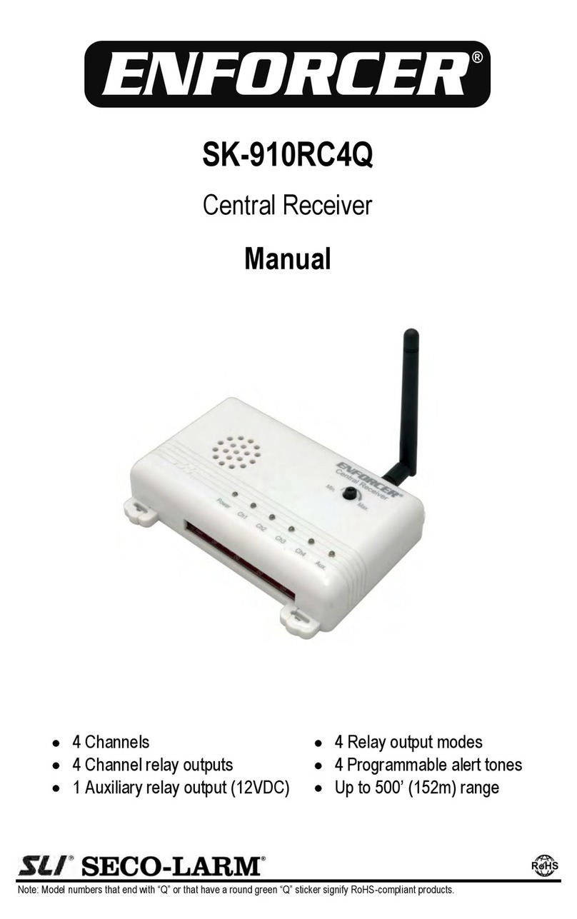
ENFORCER ENFORCER SK-910RC4Q User manual

ENFORCER
ENFORCER MVE-SV010Q User manual

ENFORCER
ENFORCER SK-910RD4 User manual

ENFORCER
ENFORCER SK-939TP2AQ User manual

ENFORCER
ENFORCER SK-910RA SERIES Operating and maintenance instructions

ENFORCER
ENFORCER SD-8202GT-PEQ User manual

ENFORCER
ENFORCER SK-910RAQ User manual

ENFORCER
ENFORCER SK-910RBQ User manual

ENFORCER
ENFORCER SK-910RB2Q User manual