Engcon DC2 QSC User manual

User manual
DC2 QSC
Article 9000405 | Version 1.4
Original Instructions

Preface
Preface
Dear Customer,
Thank you for choosing a product from engcon.
engcon is the market leader in tiltrotators and tools for excavators. We represent
innovation, knowledge and experience, and we develop our products with a focus on the
customer's needs. Please visit our website for contact information and details about the
rest of our product range.
www.engcon.com
2

Table of Contents
Table of Contents
1. Introduction
1.1. General............................................................................................................ 5
1.2. Scrapping and recycling.................................................................................. 5
1.3. Technical support and spare parts.................................................................. 5
1.4. Product approval............................................................................................. 6
1.4.1. Declaration of Incorporation.....................................................................6
2. Safety
2.1. General............................................................................................................ 7
2.2. Safety features according to 13849-1............................................................. 8
3. Design and function
3.1. DC2..................................................................................................................9
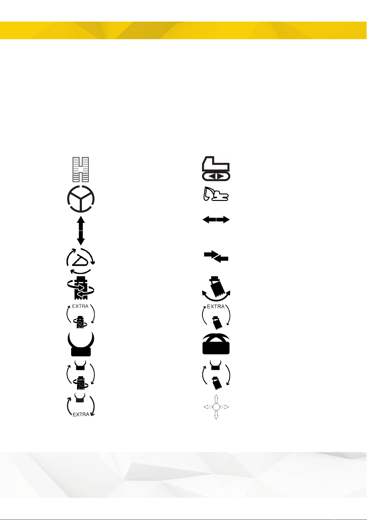
3.2. Symbols........................................................................................................... 9
3.3. Control panel - QPM....................................................................................... 13
3.3.1. Symbols on the Control Panel QPM........................................................13
3.3.2. Functions QPM - buttons.........................................................................13
3.4. Q-Safe electronics module QLM..................................................................... 15
3.4.1. QLM overview.......................................................................................... 15
4. Installation
4.1. System overview............................................................................................. 16
4.1.1. Tiltrotator control...................................................................................... 16
4.1.2. Track control............................................................................................ 17
4.1.3. Wheel control........................................................................................... 18
5. Operation
5.1. Cabin module menu system............................................................................20
5.1.1. Identification............................................................................................. 20
5.1.2. Logging in to the menu............................................................................20
5.1.3. Menu system............................................................................................21
5.1.4. User..........................................................................................................21
5.1.5. Grip.......................................................................................................... 22
5.1.6. System..................................................................................................... 23
5.1.7. Tool...........................................................................................................24
5.2. Tiltrotator quick hitch (QH).............................................................................. 25
5.2.1. Connecting the tool, hydraulic lock..........................................................25
5.2.2. Disconnecting the tool, hydraulic lock..................................................... 31
5.3. Option – slew/lift limitation...............................................................................35
5.4. Wheel control...................................................................................................37
5.5. Track control....................................................................................................37
5.6. Switching users............................................................................................... 37
6. Starting the system
6.1. Download the latest version of MicroConf.......................................................39
6.2. Connect the system to a computer................................................................. 40
3

Table of Contents
6.3. Using your engcon DC2 Android application.................................................. 41
7. Maintenance
7.1. Electrical compound........................................................................................ 63
8. Troubleshooting
8.1. Alarm list QSC-panel (QPM)........................................................................... 65
8.2. Q-Safe electronics module QLM..................................................................... 71
8.2.1. Indications................................................................................................ 71
8.2.2. Alarm........................................................................................................72
8.3. Description of electronics module QCM..........................................................73
9. Decals
9.1. Grip MIG2........................................................................................................75
9.1.1. 841868..................................................................................................... 75
9.1.2. 841869..................................................................................................... 76
9.1.3. 1047518................................................................................................... 76
9.1.4. 9000229................................................................................................... 77
9.1.5. 9000230................................................................................................... 79
9.1.6. 9000258................................................................................................... 81
9.1.7. 9000259................................................................................................... 82
9.1.8. 9000268................................................................................................... 83
9.2. Track control....................................................................................................84
9.2.1. 841163..................................................................................................... 84
9.3. Wheel control...................................................................................................85
9.3.1. 841164..................................................................................................... 85
9.3.2. 9000574................................................................................................... 85
9.3.3. 8000265................................................................................................... 86
9.4. Activation double acting function and tiltrotator control................................... 86
9.4.1. 841155..................................................................................................... 86
10. Glossary
10.1. Designations.................................................................................................. 88
10.2. Abbreviations................................................................................................. 88
11. Installation checklist
4

1 Introduction
1. Introduction
1.1. General
This user manual contain important information about your product's functions and
characteristics, and how to use it in the best way. Before you begin using the product, it is
important that you read and understand the content of these instructions, especially the
sections that address safety.
In addition to these instructions, you must study and understand the applicable safety
information for the relevant base machine as well as any other equipment involved.
The user manual is supplied with supplementary documentation providing more detailed
descriptions of the installation, fitting, operation and maintenance of control systems and
custom modifications for your specific product.
Information, images, illustrations and specifications used in the instructions are based
on product information that was available at the time of going to press. Images and
illustrations used in the instructions are typical examples and not intended to be exact
depictions of various part of the product. We reserve the right to make changes without
prior notice.
Always store the user manual together with any other supplementary information in a safe
manner and such that it is always available.
1.2. Scrapping and recycling
engcon makes constant efforts to reduce its environmental impact. engcon's products
comprise at least 99 per cent recyclable material. All assembly and service work must
take place in compliance with legislation and ordinances governing the environment,
health and occupational safety. This refers to all work with residual materials including
handling, storage and processing. To prevent contamination of soil and water, spillages
must be avoided. Should a spillage occur, it must be dealt with.
Hazardous waste may only be disposed of by those authorised to do so. All waste
produced must be disposed of in compliance with applicable legislation and ordinances:
- Metal and plastics to be recycled.
- Hydraulic hoses are normally used for energy recovery (sort as hazardous waste).
- Oils and greases are normally used for energy recovery (sort as hazardous waste).
- Electronic components to be recycled for materials (sort as hazardous waste).
- Packaging to be sorted at source and recycled for materials.
- Paper to be sorted at source and recycled for materials.
If in doubt, contact the environmental manager at engcon.
1.3. Technical support and spare parts
Contact information for support and spare parts can be found at www.engcon.com.
5

1 Introduction
1.4. Product approval
1.4.1. Declaration of Incorporation
The declaration refers to the engcon DC2 control system.
Upon reasoned request by a national authority, engcon will undertake to provide relevant information about the
machine.
The control system may not be put into operation before the machine it will be built into is in conformance with
Directive 2006/42/EG.
engcon hereby declares that the control system conforms to the below-mentioned basic safety requirements
as described in appendix 1, items1 and 3, in Directive 2006/42/EG, and that the relevant documentation as
described in appendix 7, section B has been compiled.
We hereby declare that the control system conforms with 2014/30/EC and 2006/42/EC.
Harmonised standards
Designation
SS-EN ISO 13849-1:2008
Safety of machinery – Safety-related parts of control systems –
Part 1: General principles for design
SS-EN ISO 12100:2010
Safety of machinery – General principles for design – Risk
assessment and risk reduction
SS-EN 474-1:2006+A3:2018
Earth-moving machinery – Safety – Part 1: General
requirements
SS-EN 474-5:2006+A4:2013
Earth-moving machinery – Safety – Part 5: Requirements for
hydraulic excavators
SS-EN 60204-1:2006
Safety of machinery – Electrical equipment of machines – Part
1: General requirements
SS-ISO 15998:2008
Earth-moving machinery – Machine-control systems (MCS)
using electronic components – Performance criteria and tests
for functional safety
SS-EN 13309:2010
Construction machinery – Electromagnetic compatibility of
machines with internal power supply
Stig Engström, CEO
Qualified person authorised to compile the technical documentation:
Fredrik Eklind, Product Owner - engcon Control Systems
6

2 Safety
2. Safety
REMARKS
The stated safety information is independent of the base
machine and is directly concerned with the engcon DC2.
REMARKS
Other safety instructions can be found in the tiltrotator user
manual.
2.1. General
It is important that you read and understand all warnings prior to installation work on this
product or before you use it and any accessories supplied. The warning texts highlight
potential risks and describe how to avoid them. The following warning levels are used in
this user manual:
DANGER
Indicates that an accident will occur if the regulation is
not followed. Risk of personal injury or death.
WARNING
Indicates that an accident may occur if the regulation
is not followed. Risk of personal injury or death.
CAUTION
Indicates that an accident may occur if the regulation
is not followed. Risk of personal injury.
IMPORTANT
Indicates that an accident may occur if the regulation is
not followed. Risk of damage to property, process or the
surroundings.
REMARKS
Specifies additional information that may make performance or
understanding of specific operations easier.
7

2 Safety
2.2. Safety features according to 13849-1
QSC is a safety system that complies with SS EN ISO 13849-1:2008. This means there
are risks in the system that are managed with the aid of software.
RISK 1
Risk that one of the system's quick hitch locks opens at the wrong time. This could lead to
tool disconnection and cause damage.
The risk is managed by “Safety function 1” (SF1) – blocking power to the quick hitch lock’s
solenoids. SF1: SS-EN ISO 13849-1:2008 Category 2 PL d
The following applies in all operating modes:
1
The quick hitch lock’s solenoids for the machine lock must not be powered
unless the operator simultaneously depresses both of the machine lock’s
activation buttons.
2
The quick hitch lock’s solenoids for the tiltrotator lock must not be powered
unless the operator simultaneously depresses both of the tiltrotator lock’s
activation buttons.
RISK 2
Risk that the system activates the quick hitch lock’s solenoid without tool release until
much later.
The risk is managed by “Safety function 2” (SF2) – monitoring by means of warning signal
in the panel module. SF2: SS-EN ISO 13849-1:2008 Category 2 PL c
The safety system must check that the following points are complied with:
1
The warning signal must sound when one of the quick hitch lock’s solenoids 1 or
2 is powered.
2
The warning signal must be activated for at least 1 second at system start-up as
a function test.
If any of these points is not satisfied, the power to quick hitch lock solenoid 1 and quick
hitch lock solenoid 2 must be blocked until the system is restarted.
RISK 3
Risk that the system unintentionally activates pressure in the machine's extra hydraulics.
This risk is managed by “Safety function 3” (SF3) – prevention of unintentional activation
of pressure SF3: SS-EN ISO 13849-1:2008 Category 2 PL d
The following applies in all operating modes:
1
When neither of the quick hitch lock’s buttons for opening or closing the
machine lock is depressed, pressure may not be activated.
8

3 Design and function
3. Design and function
3.1. DC2
DC2 is a proportional control system with remote support. DC2 meets the requirements
placed on all components such as hydraulics, electronics and software. Used together
with engcon tiltrotators and Q-Safe, DC2 creates a safer work environment and also
enables track control, wheel control and boom slew. The engcon DC2 smartphone app
allows remote support to supplement the PC and USB cable connection.
3.2. Symbols
Track control
Track control
Wheel control
Base machine
Drive forward/reverse
Rotation/slew right/left
Tool change in the tool
programme
Feeder Swap
Rotation
Tilt
Shift between rotation
and Extra 2
Shift between tilt and
Extra 2
Open grab
Close grab
Shift between rotation
and grab
Shift between tilt
function and grab
Shift between Extra
and grab
Joystick function
9

3 Design and function
Grab
Grab rotation
Open grab
Close grab
Clockwise grab
rotation
Anticlockwise grab
rotation
Grab bucket
Grab bucket rotation
Grab bucket open
Grab bucket close
Grab bucket clockwise
rotation
Grab bucket
anticlockwise rotation
Bucket in
Bucket out
Stick in
Stick out
Float position
Float position
Scissors open
Scissors close
Leveling blade up
Leveling blade down
10

3 Design and function
Leveling blade up/
down
Support leg up/down
Support leg up
Support leg down
Swing axle locked
Swing axle off
Boom
Boom slew
Boom slew left
Boom slew right
Side-shift
Cruise control
Auto idle
Auto idle
Auto idle
Automatic gas
Quick hitch lock(s)
Quick hitch lock valve
Quick hitch lock(s)
(Front loader)
Quick hitch lock(s)
(Excavator arm)
12V
12 Volt
F
Forward gear
24V
24 Volt
N
Neutral gear
11

3 Design and function
15A
15 Amps
R
Reverse gear
EC
15A
EC Tiltrotator
FNR
Driving direction
AUTO
Autotilt
AUX
External circuit
Open
Locked
Menu
Communication radio
Rotating brush
Hammer
Horn
Parking brake
Crawler gear
Constant flow
Low gear
High gear
Power boost
Power boost
Windscreen wipers
Main beam/dipped
beam
USER 2
User 2
USER 3
User 3
EXTRA
1
Extra function 1
EXTRA
2
Extra function 2
EXTRA
A
Extra function
Direction A
EXTRA
B
Extra function
Direction B
12

3 Design and function
EXTRA
2A
Extra function
Direction A
EXTRA
2B
Extra function
Direction B
SHEAR
User function
3.3. Control panel - QPM
3.3.1. Symbols on the Control Panel QPM
Opening the quick hitch
Closing the quick hitch
Swing/height restriction
Ground contact
Alarm indicator
Quick hitch for machine
Quick hitch for tiltrotator
3.3.2. Functions QPM - buttons
Symbol
Button press
Steady light indicates that
Initiates lock opening sequence
Lock opening sequence can be initiated
Ground contact is required
Or 1
Overrides ground contact
Or 2
Shows ground contact sensor status
The sensor detects pressure
Opens the lock
The lock can be opened
Closes the lock
The lock can be closed
13

3 Design and function
Symbol
Button press
Steady light indicates that
Confirms machine blocking
Machine blocking is active
Or 1
Cancels machine blocking temporarily
-
14

3 Design and function
3.4. Q-Safe electronics module QLM
QLM is used in combination with a Q-Safe quick hitch/machine hitch and alerts by
means of audible and visual signals if both bucket axles are not locked or in their proper
positions. This means QLM will alert when connecting and disconnecting tools or if a tool
is not properly connected.
REMARKS
For quick hitches other than Q-Safe, follow the manufacturer's
instructions for checking that tools are correctly connected.
3.4.1. QLM overview
!
!
EC
!
5
1 3 4 2
6
7
Position
Description
1
Power supply
2
Alarm indication
3
Sensor, machine hitch hook
4
Sensor, machine hitch ejector
5
Sensor, quick hitch hook
6
Sensor, quick hitch ejector
7
Warning lamp
15

4 Installation
4. Installation
4.1. System overview
4.1.1. Tiltrotator control
16

4 Installation
4.1.2. Track control
17

4 Installation
4.1.3. Wheel control
18

5 Operation
5. Operation
WARNING
If you have any doubts concerning the safety aspects
of your knowledge, the equipment or work, contact
a dealer or engcon Nordic AB. Incorrect installation
affect safety.
WARNING
Beware of moving parts. A lack of awareness may lead
to crush injuries. Risk of personal injury.
WARNING
Never attempt to increase the maximum capacity
of the equipment by modifications not approved by
the supplier. Risk of personal injury and damage to
property.
WARNING
Do not attempt to install, use or maintain your
tiltrotator/rotator and its supplied equipment before
reading and understanding all information about the
tiltrotator/rotator, its supplementary equipment and
the base machine. Pay particular attention to the
safety information.
IMPORTANT
Maintenance and repair of the electrical system may only be
carried out by professionally qualified persons.
19

5 Operation
5.1. Cabin module menu system
5.1.1. Identification
A: Part number
B: Serial number
AB
C
C: Manufacturing date
5.1.2. Logging in to the menu
CM
3
2
1
(SELECT) EXIT
4
SW7
Position
Description
1
Depress and hold down button SW7on the left and right joysticks for 5 seconds.*
2
Thumb roller in right grip.
3
Thumb roller in left grip.
4
Optional switch connected to the system.
*Applies to the standard configuration
20
This manual suits for next models
1
Table of contents
Other Engcon Industrial Equipment manuals
Popular Industrial Equipment manuals by other brands

Renova
Renova PWX Series Assembly and maintenance manual

SCHUNK
SCHUNK DPG-plus Series Assembly and operating manual

Universal
Universal 1943 Installation and maintenance instructions

Mitek
Mitek RoofTracker II Service bulletin

Inficon
Inficon Transpector CPM operating manual

Siemens
Siemens SIRIUS 3RA2933-2AA2 operating instructions