Engel HFI2230-S200 User manual

STO Safe Torque OFF
Document History
Operating Manual Rev. 1.3 www.engelantriebe.de page 2
Document History
Document
Date
(dd.mm.yyyy)
Rev
Changes
BA_STO_Entwurf_de_xxxxxx_de
xx.xx.xxxx
1.0
Erstellung Entwurf
BA_STO_Rev1.1_200518_de
18.05.2020
1.1
Installationsbeispiele 1-/2-kanalig OSSD, versch. Hinweise
ergänzt, div. Korrekturen, AC Anteil Versorgung
BA_STO_Rev1.2_200527_de
27.05.2020
1.2
Rework after Review
BA_STO_Rev1.3_210507_en
07.05.2021
1.3
First English edition
Copyright
The information and specifications in this document have been compiled with great care and to the best of our knowledge.
However, specifications differing between the document and the product cannot be eliminated with absolute certainty.
ENGEL assumes no liability whatsoever for errors or consequential damages resulting from these deviations. No liability is
assumed for damages which arise from the use of the device with the use of applications or defective circuits, either.
ENGEL reserves the right to change, supplement or improve the document or the product without prior notice. This docu-
ment may not, without the express authorization of the copyright holder, be reproduced in any way or be transmitted in
another natural or machine language or on data carrier, whether this would take place electronically, mechanically, visually
or in any other manner.

STO Safe Torque OFF
Table of Contents
Operating Manual Rev. 1.3 www.engelantriebe.de page 3
Table of Contents
DOCUMENT HISTORY.........................................................................................................................................2
TABLE OF CONTENTS..........................................................................................................................................3
1 INTRODUCTION ..............................................................................................................................................4
2 SYMBOLS USED IN THIS DOCUMENT .............................................................................................................4
3 LIST OF AVAILABLE INTEGRATED DRIVES WITH STO FUNCTION ................................................................4
4 ABBREVIATIONS USED IN THIS DOCUMENT .................................................................................................5
5 SAFETY INFORMATION ...................................................................................................................................5
5.1 General safety information ...........................................................................................................................5
5.2 Intended use ..............................................................................................................................................5
5.3 Non-intended use........................................................................................................................................6
5.4 Achievable safety level.................................................................................................................................6
5.5 Requirements for safe operation ...................................................................................................................6
5.6 Qualified personnel......................................................................................................................................7
6 FUNCTIONAL DESCRIPTION ...........................................................................................................................8
6.1 Inputs of the STO channels ..........................................................................................................................8
6.2 STO status signal ...................................................................................................................................... 10
6.2.1 Functionality of the status signal and the status output ...................................................................... 10
6.2.2 Diagnostic test................................................................................................................................ 11
6.2.3 Switch-off time of the safety function ............................................................................................... 12
6.2.4 Firmware ....................................................................................................................................... 13
6.3 Error messages ......................................................................................................................................... 14
7 TECHNICAL DATA ......................................................................................................................................... 15
7.1 System data.............................................................................................................................................. 15
7.2 Safety parameters ..................................................................................................................................... 16
7.3 Certification .............................................................................................................................................. 16
7.4 Maintenance ............................................................................................................................................. 16
8 PIN ASSIGNMENT / INSTALLATION / COMMISSIONING........................................................................... 17
8.1 X3 –STO signal plug ................................................................................................................................. 17
8.2 STO connection cable ................................................................................................................................ 17
8.3 Installation diagrams ................................................................................................................................. 18
8.3.1 Examples for dual-channel STO connection ....................................................................................... 18
8.3.2 Examples for single-channel STO connection..................................................................................... 19
8.4 Commissioning information ........................................................................................................................ 20
BA_STO_Rev1.3_210507_en
Technical changes reserved
STO –Safe Torque OFF
Introduction
Operating Manual Rev. 1.3 www.engelantriebe.de page 4
1Introduction
This document is intended solely for the description and intended use of the Safe Torque Off (STO) safety function in
accordance with EN 61800-5-2, which is available via an optional "STO module" in the integrated drives of the HFI series.
The separately available operating manual for the HFI series of integrated drives further describes their complete features
and functionalities.
2Symbols used in this document
Symbol
Signal Word
Meaning
Attention!
This symbol highlights safety and warning notices.
Non-observance can result in personal injury and/or damage to property.
Note!
This symbol highlights notes to be observed.
3List of available integrated drives with STO function
The Safe Torque Off (STO) safety function is certified and available for the integrated drives of the HFI series from ENGEL
Elektroantriebe GmbH. The STO models are equipped with an additional hardware module for this purpose and bear the
„S‟ in their type designation.
The following basic devices, optionally expandable with fieldbus interfaces, gearboxes and parking brakes, are available
with the STO safety function:
Basic Device
Part Number*1)
Description
HFI2230-S200
8822312
xxx
Basic Device HFI2230, 24V Version
HFI2230-S400
8822314
xxx
Basic Device HFI2230, 48V Version
HFI2260-S200
8822612
xxx
Basic Device HFI2260, 24V Version
HFI2260-S400
8822614
xxx
Basic Device HFI2260, 48V Version
HFI2630-S200
8826312
xxx
Basic Device HFI2630, 24V Version
HFI2630-S400
8826314
xxx
Basic Device HFI2630, 48V Version
HFI2660-S200
8826612
xxx
Basic Device HFI2660, 24V Version
HFI2660-S400
8826614
xxx
Basic Device HFI2660, 48V Version
HFI3260-S200
8832612
xxx
Basic Device HFI3260, 24V Version
HFI3260-S400
8832614
xxx
Basic Device HFI3260, 48V Version
HFI3290-S400
8832914
xxx
Basic Device HFI3290, 48V Version
HFI3760-S400
8837614
xxx
Basic Device HFI3760, 48V Version
HFI3790-S400
8837914
xxx
Basic Device HFI3790, 48V Version
*1)
"xxx"
is a placeholder for the expansion options that a basic device is equipped with.
STO –Safe Torque OFF
Abbreviations used in this document
Operating Manual Rev. 1.3 www.engelantriebe.de page 5
4Abbreviations used in this document
Abbreviation
Meaning
DCavg
Average Diagnostic Coverage
HFT
Hardware Fault Tolerance
MTTFd
Mean Time To Dangerous Failure
OSSD
Output Signal Switching Device
PELV
Protected Extra Low Voltage
PFD
Probability of dangerous Failure on Demand
PFH
Probability of dangerous Failure per Hour
PL
Performance Level
SELV
Safety Extra Low Voltage
SFF
Safe Failure Fraction
SIL (SC)
Safety Integrity Level (Systematic Capability)
STO
Safe Torque Off
5Safety information
5.1 General safety information
Always observe the safety information in the operating manual of the drive used.
5.2 Intended use
The drives of the HFI series with integrated STO module may only be used under the following conditions:
-The drive is in technically perfect condition.
-The drive is in its original condition without any unauthorised modifications.
-The limit values listed in the
Technical Data
chapters of the operating manual and in this STO document
(see chapter 7 Technical data) are complied with.
-Use in the industrial sector.
Attention!
Potential danger of the safety function becoming ineffective:
•Observe the ambient and installation conditions! (see chapter 7.1 System data)
•Never bypass the safety function!
•Do not open the housing!
•Never carry out unauthorised repairs on the device!
Attention!
In the event of damage resulting from unauthorised modification or non-intended use,
the warranty and liability claim against the manufacturer shall expire.
STO –Safe Torque OFF
Safety information
Operating Manual Rev. 1.3 www.engelantriebe.de page 6
5.3 Non-intended use
The non-intended use of the HFI integrated drives includes, among other things:
-Use outdoors.
-Use in non-industrial areas (residential areas).
-Use in applications where switching off can lead to dangerous movements or conditions.
5.4 Achievable safety level
The drives of the HFI series with integrated STO function meet the requirements of the test specifications:
-Category 3 / PL e according to EN ISO 13849-1/-2
-SIL 3 according to EN61508, IEC 61800-5-2, EN62061
Note!
The achievable safety level depends on the other components used to implement a safety
function.
5.5 Requirements for safe operation
The requirements for safe operation are:
-The correct integration of the safety function of the device into the overall system. The system/machine manufacturer
must always carry out a system/machine-specific risk assessment in accordance with DIN EN 60204-1.
-Compliance with the specifications in this STO document and in the operating manual of the entire drive.
-Consideration of the legal regulations for the place of destination.
-For emergency stop applications, protection against automatic restart must be provided according to the required
safety category.
Note!
Depending on the application, measures may be required to prevent the drive from restarting
immediately upon deactivation of the STO safety function.
Note!
Depending on the application of the drive and irrespective of its STO safety function, measures
in accordance with DIN EN 60204-1 may become necessary to prevent unexpected start-up.
Attention!
Suspended loads or externally acting load forces must be secured by means of additional
measures!

STO –Safe Torque OFF
Safety information
Operating Manual Rev. 1.3 www.engelantriebe.de page 7
5.6 Qualified personnel
The device may only be commissioned and operated by personnel who are trained in:
-the installation and operation of electrical control systems
-the applicable regulations for the operation of safety-related installations
-the applicable regulations for accident prevention and occupational safety
-the available documentation on the drives with STO functionality
Note!
The design of a system according to safety aspects requires expert knowledge. A safe system
can only be achieved after expert, normative assessment.
The mere use of safety components without further assessment is not sufficient!
STO –Safe Torque OFF
Functional description
Operating Manual Rev. 1.3 www.engelantriebe.de page 8
6Functional description
The Safe Torque Off (STO) function is ensured by a redundant pulse inhibit. When the STO safety function is engaged,
the pulse inhibit disconnects the torque-determining pulse patterns (PWM) generated by the drive's microcontroller from
the power stage. Without suitable pulse patterns, the power stage is unable to develop a continuous torque in the motor
system, the motor is de-energised and torque-free.
6.1 Inputs of the STO channels
The safe pulse inhibit of the STO module has a dual-channel redundant design. Each channel has a digital input to control
its safety sub-function of the pulse inhibit.
When both STO channels are voltage-free (0 V), e.g. both inputs are open, the pulse inhibit is safely activated.
When both STO channels are supplied with voltage (24 V), the pulse inhibit is deactivated and the drive can be operated.
Activation of the STO function ➔Channel STO1 = 0 V AND Channel STO2 = 0 V
Normal operation of the drive ➔Channel STO1 = 24 V AND Channel STO2 = 24 V
Both STO channels must always be operated simultaneously and consistently, i.e. equivalently.
The STO inputs allow a direct connection to …
-safe switching contacts such as electromechanical safety relays,
-safe semiconductor outputs such as electronic safety relays,
-passive safety sensors such as position switches with forcibly guided contacts
(see Figure 6-1: STO function with emergency stop device),
-active safety sensors such as light grids with OSSD signals
(see Figure 6-2: STO function with OSSD signals).
Test pulses from OSSD switching devices type C with a pulse duration of ≤ 1.0 ms and a period duration ≥ 500 ms do not
affect the safety function. This means that the test pulses are safely blanked and that the STO function will not be activated.
Note!
No cross-circuit detection of STO channels 1 and 2 is performed, neither by the STO module
nor by the drive.
According to DIN EN 61800-5-2, a cyclical test must be carried out every 3 months at the
latest to ensure the specified PFH value (see chapter 6.2.2 Diagnostic test).
Attention!
Note the following systematic behaviour of the drive:
In the event of a fault, a possible movement of the motor shaft of 60° (mech.)
cannot be ruled out, even if the STO safety function is activated!
When the safety function is activated and a defect occurs at the internal power stage on at
least two of the three motor phases, i.e. a total of two defects, motor phases can be energised.
In this case, a torque and a limited movement of the motor shaft may occur despite the
activated safety function, whereby the maximum angle of rotation of the motor shaft is limited
to 180° of the electrical period of the motor. For the 6-pole motor systems of the HFI series,
this corresponds to a mechanical angle of rotation of 60°.
STO –Safe Torque OFF
Functional description
Operating Manual Rev. 1.3 www.engelantriebe.de page 9
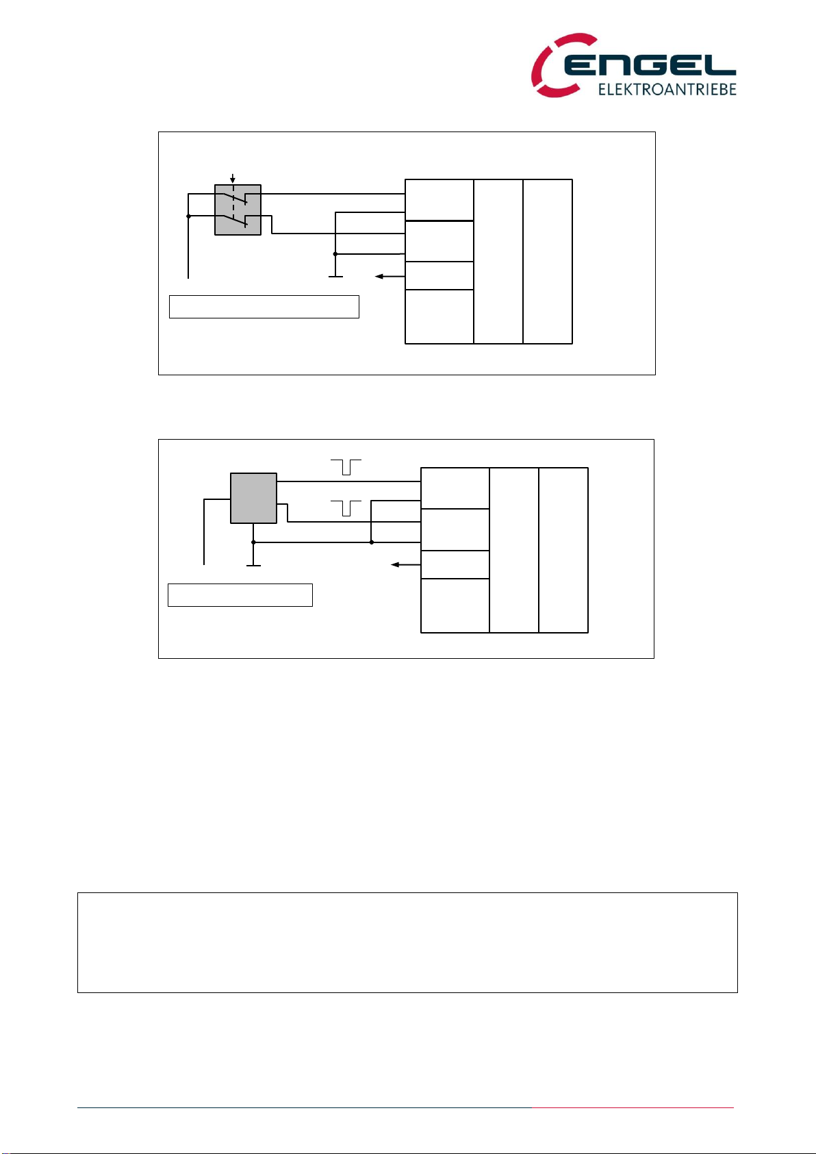
Figure 6-1: STO function with emergency stop device
Figure 6-2: STO function with OSSD signals
The integrated drive can be supplied by either a PELV or SELV power source.
The safety circuit, i.e. the STO channels, can as well be supplied by either a PELV or SELV power source.
For drives with a supply voltage of 24 V, it is permissible to supply the STO channels from the 24 V power supply of the
integrated drive.
Each STO input and the status output are galvanically isolated from each other and from the control electronics of the
integrated drive.
Note!
An incorrect wiring of the STO inputs can result in a lower safety level. By connecting input
„a‟to „c‟, for example, the external dual-channel structure of the system is lost.
STO Input 1
STO Input 2
STO Status
Controller
Pulse
Inhibit
Power
Stage
and
Motor
a
b
c
d
S
Emergency Stop
Device
GND
24 VDC
SELV/PELV Power Supply
HFI-Sx00
STO Input 1
STO Input 2
STO Status
Controller
Pulse
Inhibit
Power
Stage
and
Motor
a
b
c
d
S
OSSD
Switching Device
GND
24 VDC
SELV/PELV Power Supply
Output 1
Output 2
HFI-Sx00
Test Pulses

STO –Safe Torque OFF
Functional description
Operating Manual Rev. 1.3 www.engelantriebe.de page 10
6.2 STO status signal
6.2.1 Functionality of the status signal and the status output
The status of the STO safety function is signalled via a potential-free semiconductor output. Only when the safety function
is activated the semiconductor output is closed, i.e. conductive.
The status output can be used to signal the status of the safety function to a higher-level control unit.
The status output has reverse polarity protection and is protected against overload and short circuit by a resettable fuse.
Channel1
VSTO1
Channel2
VSTO2
Status Output
Note
0 …5 V
(OFF)
0 …5 V
(OFF)
closed / conductive
Both STO channels voltage-free, unsupplied:
STO active = safe state
24 V
(ON)
0 …5 V
(OFF)
open / non-conductive
Invalid state:
STO channels inconsistently driven
0 …5 V
(OFF)
24 V
(ON)
open / non-conductive
Invalid state:
STO channels inconsistently driven
24 V
(ON)
24 V
(ON)
open / non-conductive
Both STO channels supplied with voltage:
Safety function deactivated,
normal operation of the drive available
Figure 6-3: Circuit diagram of the status output
STO –Safe Torque OFF
Functional description
Operating Manual Rev. 1.3 www.engelantriebe.de page 11
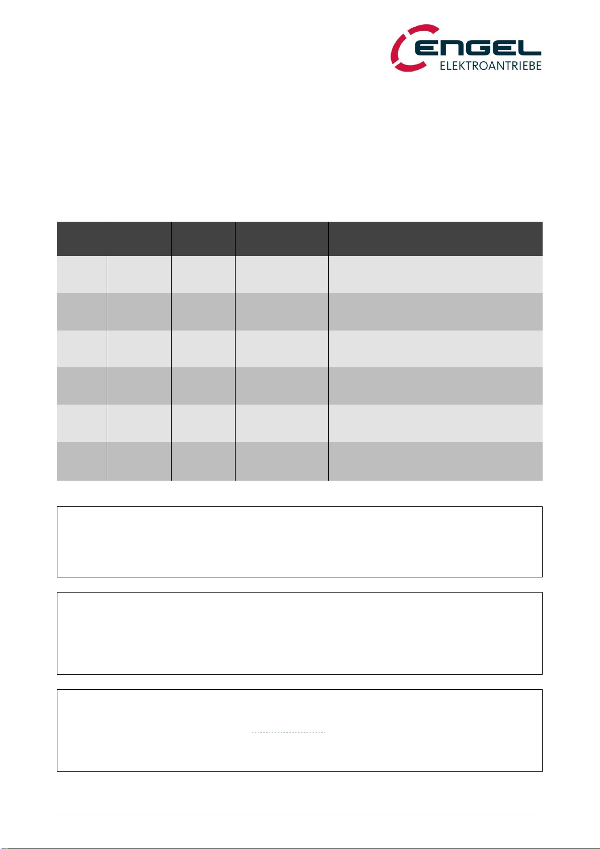
6.2.2 Diagnostic test
According to DIN EN 61800-5-2, a cyclical test of the proper function of the status output must be carried out at least
every 3 months to ensure the specified PFH value.
For this purpose, the two STO channels are stimulated in a test sequence with different input states (test steps 1 –6).
In each test step, the state of the status output is compared to its target state specified in the table below. The correct
function of the status output is only fulfilled, when the status output reacts according to the target states in all 6 test steps
in succession.
The test sequence can be carried out manually or automatically by means of a control unit.
Test
Step
Channel1
VSTO1
Channel2
VSTO2
Status Output
Target State
Note
1
0 …5 V
(OFF)
0 …5 V
(OFF)
closed
conductive
Both STO channels voltage-free, unsupplied:
STO active = safe state
2
24 V
(ON)
0 …5 V
(OFF)
open
non-conductive
Invalid state:
STO channels inconsistently driven
3
0 …5 V
(OFF)
0 …5 V
(OFF)
closed
conductive
Both STO channels voltage-free, unsupplied:
STO active = safe state
4
0 …5 V
(OFF)
24 V
(ON)
open
non-conductive
Invalid state:
STO channels inconsistently driven
5
0 …5 V
(OFF)
0 …5 V
(OFF)
closed
conductive
Both STO channels voltage-free, unsupplied:
STO active = safe state
6
24 V
(ON)
24 V
(ON)
open
non-conductive
Both STO channels supplied with voltage:
Safety function deactivated,
normal operation of the drive available
Note!
The status signal / status output is for diagnostic purposes only and has no safety rele-
vance. It must not be used in the safety circuit!
Note!
Measuring and contact points should be provided (in the control cabinet, for example) to make
a manual diagnostic test possible and practicable.
A software aided diagnostic test is permissible.
Note!
The values listed under Safety parameters are valid on condition that the specifications of this
diagnostic test are observed. Therefore, the diagnostic test must be carried out for dual-chan-
nel systems as well as for single-channel systems.
STO –Safe Torque OFF
Functional description
Operating Manual Rev. 1.3 www.engelantriebe.de page 12
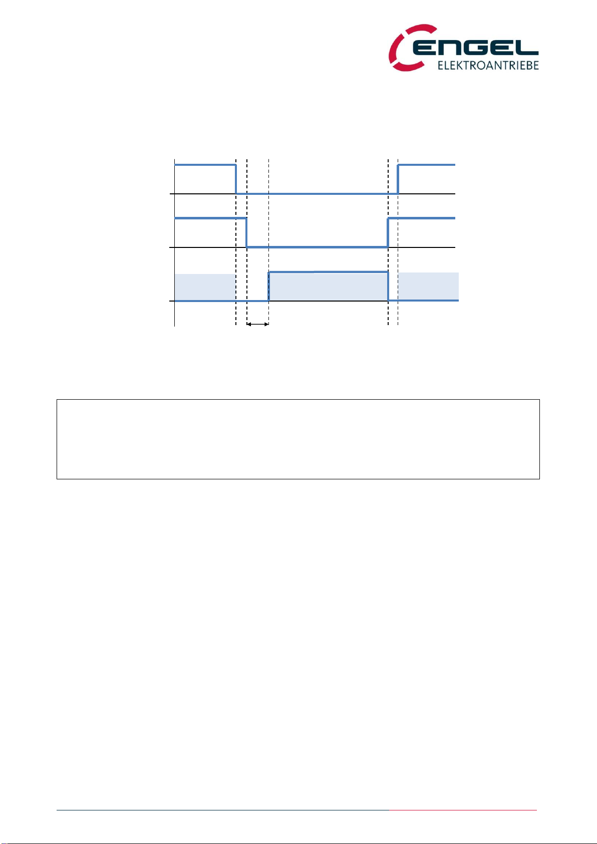
6.2.3 Switch-off time of the safety function
After both STO channels are de-energised (0 V …VSTO1/2 …5.0 V), the safety function (disconnection of the PWM pulse
patterns) is guaranteed after a switch-off time of 20 ms max.
Figure 6-4: STO function switch-off time
Note!
There is no discrepancy time monitoring between the signals STO1 and STO2! This means
that there is no defined time interval within which both STO input signals must have reached
the same switching state.
STO1
0 V
24 V
STO2
0 V
24 V
Status
non-
conductive
conductive
STO active
Normal
operation
Normal
operation
Switch-off time
STO –Safe Torque OFF
Functional description
Operating Manual Rev. 1.3 www.engelantriebe.de page 13
6.2.4 Firmware
The STO functionality is supported from firmware version V4.00 of the HFI series of integrated drives. The pulse inhibit of
the STO is hardware-based, i.e. the firmware of the integrated drives has no influence on the STO safety function. The
firmware is not safety-relevant.
The pulse inhibit is available at all times and works independently of other settings and operating modes of the integrated
drives.
The firmware monitors the internal signal voltages of the STO channels as well as the temperature of the STO module. In
the event of impermissible operating conditions, error messages are triggered that switch off the drive via its standard
functionality.
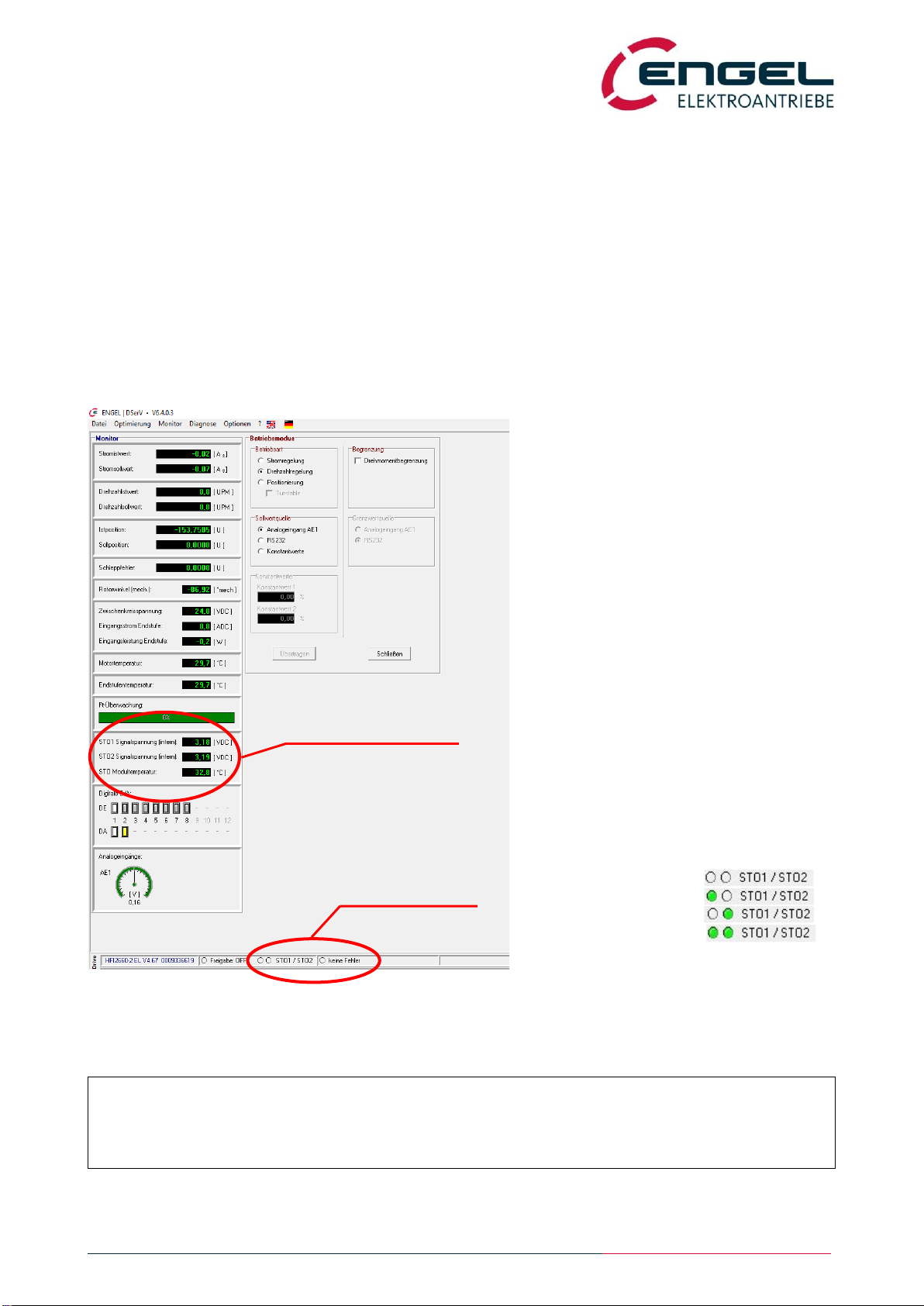
From version V6.403, the parameterisation software DSerV supports the STO functionality.
Figure 6-5: DSerV with STO visualisation
Note!
The parameterisation software DSerV is described in the operating manual of the HFI series.
STO status indication
and error indication
Internal signal voltages
and module temperature
STO STO
input signals status indication
STO1= 24 V / STO2= 24 V
STO1= 0 V / STO2= 24 V
STO1= 24 V / STO2= 0 V
STO1= 0 V / STO2= 0 V
STO –Safe Torque OFF
Functional description
Operating Manual Rev. 1.3 www.engelantriebe.de page 14
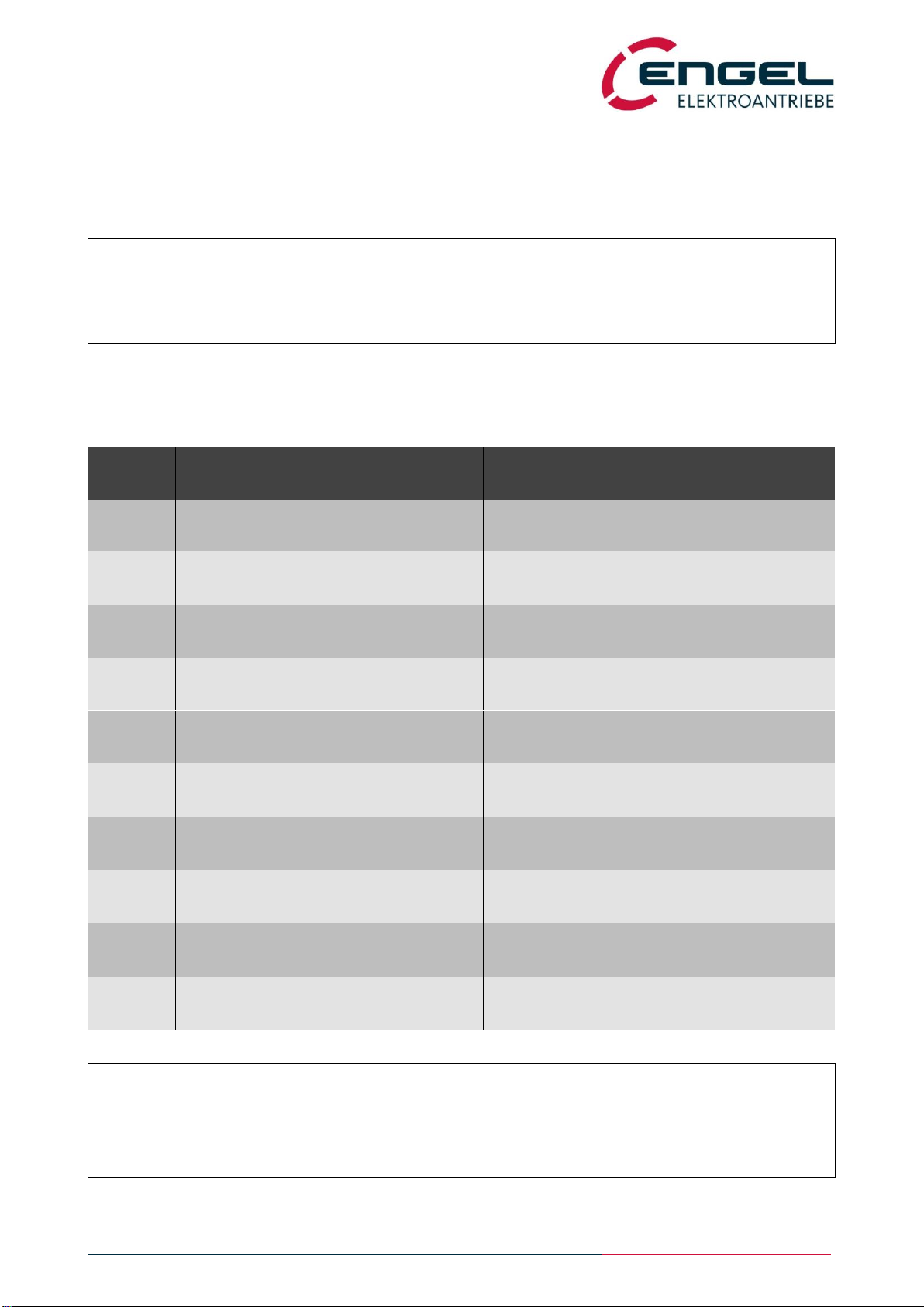
6.3 Error messages
The firmware of the integrated drive monitors various variables and conditions and triggers error messages (including STO
error messages) as soon as defined limit values or tolerance ranges are exceeded. In this case, the drive is deactivated,
but solely via its normal, non-safe function.
Some of the STO error messages are only triggered when the controller enable of the integrated drive is active, i.e. without
controller enable only the temperature monitoring of the STO module is active and no other STO error messages are
triggered. The following table lists the error messages resulting from the non-safety-relevant monitoring of the STO
module.
Error Code
(Fieldbus)
Error Code
(DSerV)
Error Description
Cause / Measure for error rectification
F080h
13.00000
Generic STO error
Internal error / No action
F081h
13.00002
Signal voltage STO1 ≤min
STO channel 1 voltage too low /
Operate STO channel with the specified voltage
F082h
13.00003
Signal voltage STO1 ≥max
Internal error / No action
F083h
13.00257
Temperature of STO > 115 °C
Overheat / Check operating conditions
F084h
13.00512
Signal voltage STO2 ≤min
STO channel 2 voltage too low /
Operate STO channel with the specified voltage
F085h
13.00514
Signal voltage STO1 ≤min
and
Signal voltage STO2 ≤min
STO channel 1+2 voltages too low /
Operate STO channels with the specified voltage
F086h
13.00515
Signal voltage STO1 ≥max
and
Signal voltage STO2 ≤min
Internal error / No action
F087h
13.00768
Signal voltage STO2 ≥max
Internal error / No action
F088h
13.00770
Signal voltage STO1 ≤min
and
Signal voltage STO2 ≥max
Internal error / No action
F089h
13.00771
Signal voltage STO1 ≥max
and
Signal voltage STO2 ≥max
Internal error / No action
Note!
For a safe deactivation of the drive, it is always required that the STO function is activated!
This also applies if the drive has already been deactivated due to an error message.
Note!
If internal errors occur, the unit must be replaced!
Repairs and interventions by the user are not permitted!

STO –Safe Torque OFF
Technical data
Operating Manual Rev. 1.3 www.engelantriebe.de page 15
7Technical data
7.1 System data
Designation
Unit
Value
Additional information
min
typ
max
Permissible input voltage
STO channel 1/2 (VSTO1/VSTO2)
VDC
0
28.8
SELV/PELV
Overvoltage protection up to 60 V
Input voltage for deactivation
of STO channel 1/2
VDC
20.4
28.8
24 V -15 % / +20 % (≤ 5 % AC)
VSTO1 / VSTO2
Input voltage for activation of
STO channel 1/2
VDC
0
5.0
Current consumption
STO channel 1/2
mA
12
at VSTO1/2 = 24 V
Status output reverse voltage
VDC
24
30
Load current max. 50 mA
Voltage drop at 50 mA:
U ≤2 V
STO switch-off time
ms
20
Time between activation of the
STO function and the safe deacti-
vation of the power stage
Ambient temperature
°C
0
40
No condensation permissible
Storage temperature
°C
-25
75
No condensation permissible
Permissible altitude
m
2000
[m above sea level]
Max. cable length
m
20
Permissible max. cable length
of the STO inputs (M12 con-
nector)
OSSD pulse duration
ms
1.0
OSSD period duration
ms
500
Working life
years
20
due to design
Electromagnetic compatibility
Emission*1)
DIN EN 61800-3: 2019-04
According to category C2
Immunity
DIN EN 61800-3: 2019-04
DIN EN 61800-5-2: 2017-11 *2)
According to category C3
/ second environment
Insulation strength
Overvoltage Category III Surge Voltage 800 V
between each STO channel,
status output and control unit
*1) Conducted emissions towards the AC mains must be suppressed in the power supply unit of the device.
*2) Concerning the functional safety.
STO –Safe Torque OFF
Technical data
Operating Manual Rev. 1.3 www.engelantriebe.de page 16
7.2 Safety parameters
Designation
Unit
Standard
Additional information
62061
61508
13849
HFT
1
1
Hardware fault tolerance
PFH
1/h
4.73 ∙ 10-11
9.12 ∙ 10-11
Probability of dangerous failure
per hour
PFD
1.04 ∙ 10-7
7.89 ∙ 10-6
Probability of dangerous failure
on demand
SFF
%
99.92
99.92
Safe failure fraction
(Percentage of failures that do
not affect the safety function)
SIL (SC)
3
3
Safety integrity level
DCavg
%
0.00
Average diagnostic coverage
MTTFd
years
25974
Mean time to dangerous failure
PL
e
Performance level
Cat
3
Category
7.3 Certification
Designation
Type examination
The functional safety technology of the product has been tested and certified as a
safety component to Annex IV of the European Machinery Directive 2006/42/EG.
Safety function „Safe Torque Off‟ (STO) according to DIN EN 61800-5-2 2017
Safety of machinery.
Certificate-issuing authority
TÜV Rheinland Industrie Service GmbH, Köln
7.4 Maintenance
The integrated drives from ENGEL Elektroantriebe GmbH do not require any special maintenance measures. A defective
drive must be completely replaced. Repairs are not permitted.
STO –Safe Torque OFF
Pin assignment / Installation / Commissioning
Operating Manual Rev. 1.3 www.engelantriebe.de page 17
8Pin assignment / Installation / Commissioning
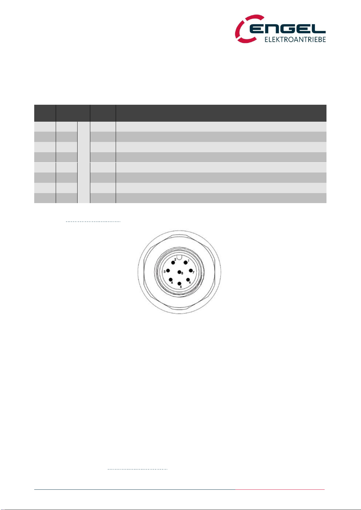
8.1 X3 –STO signal plug
Connector on the device: 8-pin M12 circular connector (male, A-coded)
Mating plug: 8-pin M12 circular connector (female, A-coded)
Pin-
No.
Wire 1
Name
Description
1
WH
8 x 0.25 mm2
Status+
Potential-free status output (positive potential, collector)
2
BN
Status-
Potential-free status output (negative potential, emitter)
3
GN
STO1-
STO channel 1 supply, reference potential, 0 V
4
YE
STO1+
STO channel 1 supply, positive potential, 24 V
5
GY
n.c.
6
PK
STO2+
STO channel 2 supply, positive potential, 24 V
7
BU
STO2-
STO channel 2 supply, reference potential, 0 V
8
RD
n.c.
1Wire colours and cross-sections apply to assembled STO connection cables from ENGEL Elektroantriebe GmbH
(see chapter 8.2 STO connection cable).
8.2 STO connection cable
Recommendations for the properties of the STO connection cable:
● recommended wire cross-section: 0.25 mm²
● overall shield
● suitable for drag chains, operating temperature min. +80 °C
● cable length max. 20 m
ENGEL original accessories:
Item-No.: 9900000650 SK_STO_M12_NC_5 signal cable STO | M12 | NC length 5 m
Item-No.: 9900000651 SK_STO_M12_NC_15 signal cable STO | M12 | NC length 15 m
Cable assembly with M12 connection plug, open on one end,
8 x 0.25 mm², overall shield, PUR, -30 °C … +90 °C, suitable for drag chains.
(For wire colours, see chapter 8.1 X3 –STO signal plug.)
Figure 8-1: Pin layout of the STO signal plug
View on the mating side of the receptacle on the drive

STO –Safe Torque OFF
Pin assignment / Installation / Commissioning
Operating Manual Rev. 1.3 www.engelantriebe.de page 18
8.3 Installation diagrams
8.3.1 Examples for dual-channel STO connection
Figure 8-2: Dual-channel STO connection with emergency stop device
Figure 8-3: Dual-channel STO connection with OSSD switching device
The installation diagrams in the figures above show the dual-channel connection assignment of the STO function.
STO –Safe Torque OFF
Pin assignment / Installation / Commissioning
Operating Manual Rev. 1.3 www.engelantriebe.de page 19
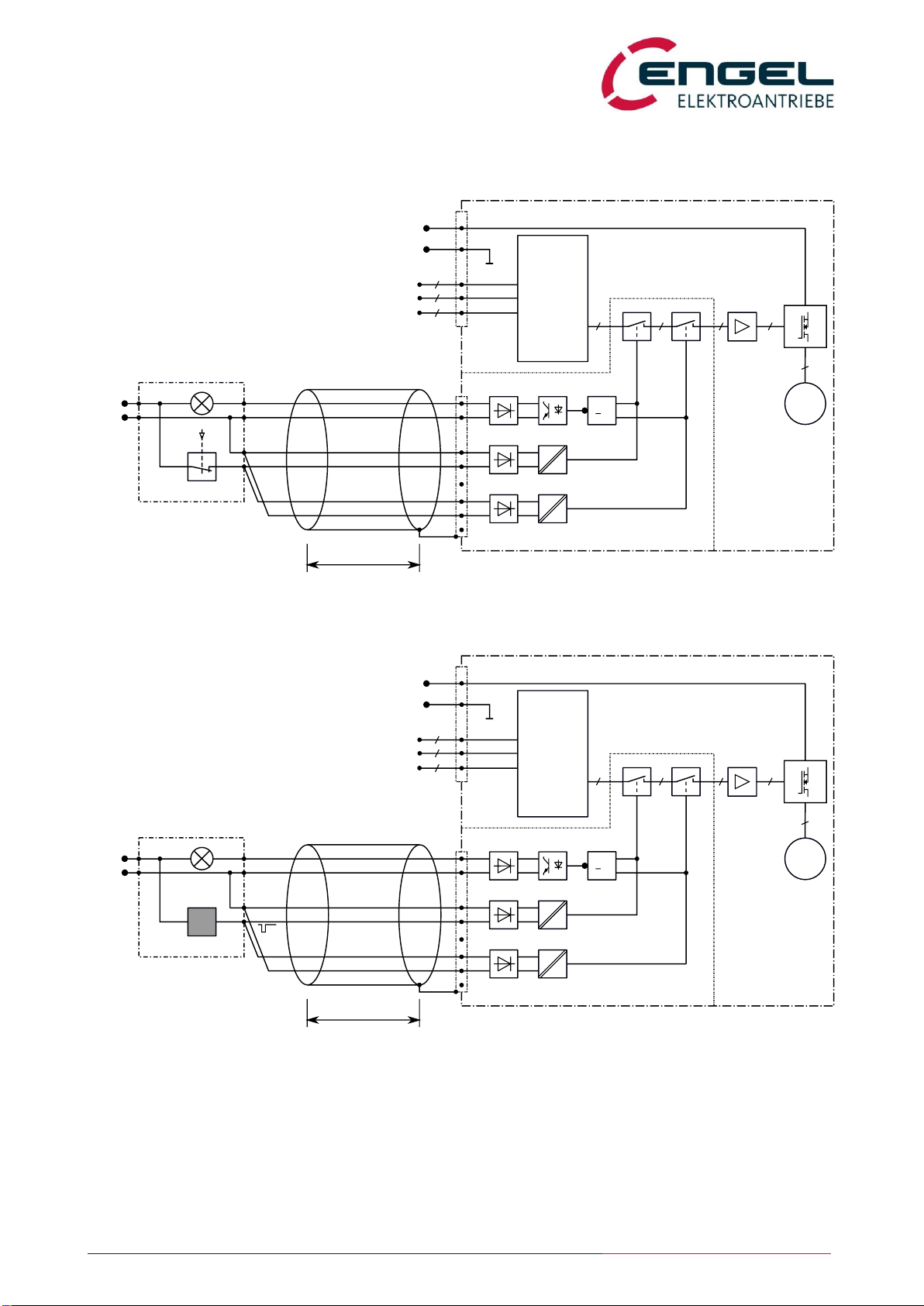
8.3.2 Examples for single-channel STO connection
Figure 8-4: Single-channel STO connection with emergency stop device
Figure 8-5: Single-channel STO connection with OSSD switching device
The installation diagrams in the figures above show the single-channel connection assignment of the STO function.

STO –Safe Torque OFF
Pin assignment / Installation / Commissioning
Operating Manual Rev. 1.3 www.engelantriebe.de page 20
8.4 Commissioning information
In addition to the commissioning instructions described in the operating manual of the HFI series, the following steps have
to be executed:
Step 1: Wire the connections of the STO module properly according to the installation diagram.
Step 2: Check the wiring.
Step 3: Validate the functionality of the drive and the safety function.
Step 4: Perform a diagnostic test according to chapter 6.2.2 Diagnostic test.
This manual suits for next models
12
Table of contents
Other Engel Servo Drive manuals


