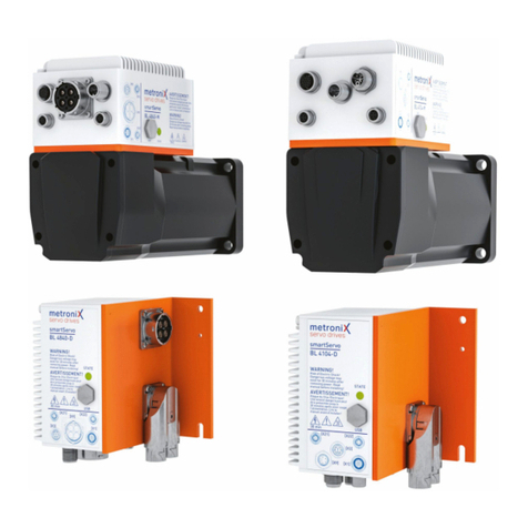
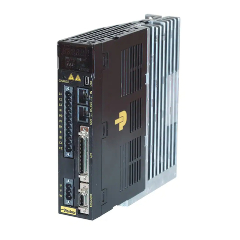
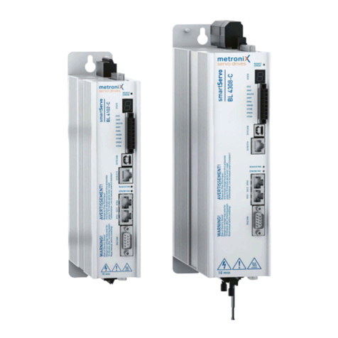
Metronix smartServo BL 4000-C Series User manual

Important!
Read thoroughly before use!
Retain for future reference!
Product manual
smartServo BL 4000-C

Original product manual
Copyrights
© 2019 Metronix Meßgeräte und Elektronik GmbH. All rights reserved.
The information and data in this document have been composed to the best of our
knowledge. However, deviations between the document and the product cannot be
excluded entirely. For the devices and the corresponding software in the version handed
out to the customer, Metronix guarantees the contractual use in accordance with the user
documentation. In the case of serious deviations from the user documentation, Metronix
has the right and the obligation to repair, unless it would involve an unreasonable effort. A
possible liability does not include deficiencies caused by deviations from the operating
conditions intended for the device and described in the user documentation.
Metronix does not guarantee that the products meet the buyer’s demands and purposes
or that they work together with other products selected by the buyer. Metronix does not
assume any liability for damage resulting from the combined use of its products with other
products or resulting from improper handling of machines or systems.
Metronix reserves the right to modify, amend or improve the document or the product
without prior notification.
This document may, neither entirely nor in part, be reproduced, translated into any other
natural or machine-readable language nor transferred to electronic, mechanical, optical or
any other kind of data media, without the express authorisation of the author.
Trademarks
Any product names in this document may be registered trademarks. The sole purpose of
any trademarks in this document is the identification of the corresponding products.
EtherCAT® is a registered trademark and patented technology, licensed by Beckhoff
Automation GmbH, Germany.
MetronixServoCommander®is a registered trademark of Metronix Meßgeräte und
Elektronik GmbH.
Product manual BL 4000-C Page 2 of 298

Contact
Metronix Meßgeräte und Elektronik GmbH
Kocherstraße 3
38120 Braunschweig
Germany
Telefon: +49 (0)531 8668 0
Telefax: +49 (0)531 8668 555
E-mail: vertrieb@metronix.de
https://www.metronix.de
Revision Information
Manual title Product manual "BL 4000-C"
File name P-HB_BL 4000-C_1p0_EN.pdf
Version 1.0
Year 2019
Product manual BL 4000-C Page 3 of 298

Table of Contents
Table of Contents
1 About this Product manual 13
1.1 Explanations and notation 13
1.1.1 Structure of the warning notes 13
1.1.2 Notation in this product manual 14
1.2 Additional documents 14
1.3 Order numbers 14
1.4 Applicable standards 15
2 For your own safety 16
2.1 General information 16
2.2 Intended use 17
2.3 Target group 17
2.4 General safety instructions 18
2.5 Personal protective equipment 19
2.6 Safety notes for installation and maintenance 19
2.7 Protection against contact with electrical parts 21
2.8 Protection against electric shock by way of protective extra-low voltage (PELV) 22
2.9 Protection against dangerous movements 22
2.10 Protection against contact with hot parts 23
2.11 Protection during the handling and installation of the devices 23
3 Product description 24
3.1 Type designation 24
3.2 Device view 25
3.3 Features 27
4 Quick-start guide 30
4.1 Using the parameterisation program 32
4.1.1 The user interface 32
4.1.2 Setting up the communication 33
4.1.2.1 Communication via USB 33
Product manual BL 4000-C Page 4 of 298

Table of Contents
4.1.2.2 Communication via Ethernet 34
4.1.2.3 Changing the communication interface 36
4.1.2.4 Communication errors 36
4.1.2.5 Numeric input fields for changing parameters online 37
4.2 Operating mode and error indication 38
4.3 Operability check 39
4.4 Software-guided commissioning 40
4.4.1 General configuration 41
4.4.2 Configuration of the display unit 45
4.4.2.1 Rotatory operation 45
4.4.2.2 Translatory operation 45
4.4.2.3 Other setting options 45
4.4.3 Adjusting the input limits 46
4.4.4 Configuration of the motor data 47
4.4.5 Safety parameters 49
4.4.6 Motor temperature monitoring 52
4.4.7 Commutation encoder 53
4.4.8 Angle encoder settings 54
4.4.9 Angle encoder identification (automatic determination) 55
4.4.10 Automatic identification of the current controller 56
4.4.11 Configuring the polarity of the limit switches 56
4.4.12 Configuration of the speed controller (auto-tuning with FAST) 57
4.4.13 Configuration of the position controller 59
4.4.14 Permanent storage of the parameters 61
5 Enabling the servo drive and selecting the set values 62
5.1 Configuring the enable logic 62
5.2 Operating modes 65
5.2.1 Torque-controlled mode (torque control) 65
5.2.2 Speed-controlled mode (speed control) 66
5.2.3 Position-controlled mode and positioning mode (positioning process) 67
5.2.4 Using the servo drive in jog mode 68
Product manual BL 4000-C Page 5 of 298

Table of Contents
5.3 Selecting the setpoints 69
5.3.1 Specifying the setpoints (speed and torque values) 70
5.3.2 Settings concerning the analogue input AIN 71
5.3.3 Offset calibration and "Safe zero" 72
6 Applications 73
6.1 Homing process 73
6.1.1 Methods -17 and -18: Stop 74
6.1.2 Methods -1 and -2: stop with index pulse evaluation 74
6.1.3 Methods 17 and 18: positive and negative limit switch 75
6.1.4 Methods 1 and 2: positive and negative limit switch with index pulse evaluation 75
6.1.5 Methods 23 and 27: reference switch 76
6.1.6 Methods 7 and 11: reference switch and index pulse evaluation 77
6.1.7 Methods -23 and -27: homing run (positive/negative) to the reference switch 78
6.1.8 Methods 32 and 33: homing to the index pulse 78
6.1.9 Method 34: homing to the current position 79
6.1.10 Parameterisation of the homing method 79
6.1.11 Parameterisation of the homing run: settings 80
6.1.12 Parameterisation of the homing run: motion profile 82
6.1.13 Tab: Index pulse control 83
6.1.14 Tab: Torques 84
6.1.15 Tab: Special functions 85
6.2 Positioning process 86
6.2.1 Global positioning settings 86
6.2.2 Destination parameters: general buttons 87
6.2.3 Destination parameters: Settings tab 88
6.2.4 Destination parameters: Driving profile tab 90
6.2.5 Destination parameters: Experts tab 92
6.2.6 Moving to specific positions 95
6.2.6.1 Positioning via digital inputs 95
6.2.6.2 Positioning via the parameterisation interface (USB/Ethernet) 95
6.2.7 Motion program 97
Product manual BL 4000-C Page 6 of 298

Table of Contents
6.2.7.1 Linking positions 98
6.2.7.2 Global settings 100
6.2.7.3 Digital inputs - Motion program 101
6.2.8 Jog mode 102
6.2.9 Setting of digital outputs 103
6.3 Applications with several angle encoders 104
6.3.1 Improved position control with two angle encoders 105
6.3.2 Synchronisation/parameterisation of the master 106
6.3.3 Synchronisation/parameterisation of the slave 106
6.3.4 Position-synchronous operation 107
6.3.5 Special considerations concerning the resolution of the master frequency 107
6.4 Flying saw 108
6.4.1 Conventional synchronisation 109
6.4.2 Parameterisation and configuration 110
6.4.3 Synchronisation activation and deactivation (example) 111
6.4.4 Starting position/position set 0 111
6.4.5 Gripping of the object/position set 1 112
6.4.6 Depositing of the object/position set 2 113
6.4.7 Starting position/position set 0 113
6.4.8 Wiring 114
6.4.9 Compensation of constant delays 114
6.4.10 Mechanical compensation (lead) 114
6.4.11 Compensation by calculation 114
6.4.12 Triggering the starting process based on several sources 115
6.4.13 Position offset due to cycle times 115
6.4.14 Lead of the actual position when the light barrier is not located in the range of
movement of the drive 115
6.4.15 Summary 116
6.5 Rotary axis mode 117
7 Additional settings 119
7.1 Bluetooth® communication 119
Product manual BL 4000-C Page 7 of 298

Table of Contents
7.2 Oscilloscope 120
7.2.1 Oscilloscope window 120
7.2.2 Oscilloscope settings 122
7.2.2.1 Tabs: CH1 ... CH8 122
7.2.2.2 Tabs: Time base 124
7.2.2.3 Tabs: Trigger 125
7.3 Display units 126
7.3.1 User-defined display units 126
7.3.2 Direct input of the display units 127
7.4 Parameter sets 128
7.4.1 Online parameterisation: Overview 128
7.4.2 Loading and saving parameter sets 129
7.4.3 Offline parameterisation: 130
7.4.4 Parameterisation via a microSD card 131
7.5 Angle encoder settings 134
7.5.1 "Commutating-generator" tab 134
7.5.2 "X2A" tab 135
7.5.3 "X2B/X6" tab 136
7.5.3.1 General settings 137
7.5.3.2 Digital incremental encoders 139
7.5.3.3 Analogue incremental encoders 141
7.5.3.4 Serial:EnDat2.2 143
7.5.3.5 Serial:HIPERFACE 144
7.5.3.6 Serial:HIPERFACEDSL 145
7.5.3.7 Serial:BiSS 146
7.5.3.8 Storing parameters in the encoder 148
7.5.4 "X1" tab 151
7.6 Parameterisation of the motor and output stage 153
7.6.1 Methods for analysing motor problems 153
7.6.2 Configuration of the output stage 154
7.6.3 Use of linear motors 154
Product manual BL 4000-C Page 8 of 298

Table of Contents
7.6.3.1 Fundamental parameterisation of linear motors 155
7.6.3.2 Determining the commutation position in the case of linear motors 158
7.6.3.3 Settings in the homing menu for linear motors 160
7.6.3.4 Necessary error reactions in the case of linear motors 161
7.6.4 Manual optimisation of the controllers 162
7.6.4.1 Motor requirements 162
7.6.4.2 Reversing generator 164
7.6.4.3 Manual speed control configuration 164
7.6.4.4 Manual optimisation of the position controller 167
7.7 Digital inputs 168
7.7.1 Configuration of the digital inputs 169
7.8 Digital outputs 172
7.8.1 Configuration of the digital outputs 173
7.8.2 Configuration of the messages for the digital outputs 174
7.8.2.1 Torque message window: "Comparison torque" 174
7.8.2.2 Speed message window: "Comparison speed reached" 175
7.8.2.3 Target position message window: "Xactual=Xtarget" 176
7.8.2.4 Following error message window: "Following error" 177
7.9 Position triggers 178
7.9.1 Position triggers 180
7.9.2 Rotor position triggers 181
7.10 Brake control and automatic brake 182
7.11 Configuration of the DC bus monitoring function 184
7.12 External braking resistor 185
7.13 DC bus coupling 186
7.14 DC supply 187
7.15 Control circuit cycle times 187
7.16 Band-stop filters 189
7.17 Motor temperature monitoring system 190
7.17.1 Parameterising the characteristic (linear/non-linear sensor) 190
7.17.2 Temperature limits and monitoring functions 191
Product manual BL 4000-C Page 9 of 298

Table of Contents
7.18 Limit switch, setpoint direction limitation 192
7.19 Firmware download 192
8 STO (safe torque off) 193
8.1 Special safety instructions 193
8.2 Certification/safety level 193
8.3 Requirements for using the product 194
8.3.1 Qualification of the specialist personnel (personnel requirements) 194
8.3.2 Diagnostic coverage (DC) 194
8.4 Purpose 195
8.5 Principle of operation and use 196
8.5.1 Description of the STO safety function 196
8.5.2 Overview of the [X3] interface 197
8.5.3 Control inputs STOA, GNDA/STOB, GNDB [X3] 198
8.5.4 Discrepancy time 198
8.5.5 Test pulses 199
8.5.6 Auxiliary supply [X3] 199
8.5.7 Additional diagnostics functions 199
8.6 Circuit examples 201
8.6.1 Safe torque off (STO) 201
8.6.2 Deceleration and safe torque switch off(SS1, "Safe Stop 1") 202
8.7 Prior to commissioning 204
8.8 MetronixServoCommander® safety functions 204
8.8.1 Servo drive type indication and safety function 204
8.8.2 Status indication of the finite state machine 205
8.8.3 "Safety module (integrated)" window 206
8.9 Functional test, validation 207
8.10 Operation 207
8.11 Diagnostics and fault clearance 207
9 Fault messages 208
9.1 Error management 210
9.2 Error buffer 211
Product manual BL 4000-C Page 10 of 298

Table of Contents
10 Storage/transport 212
11 Installation 213
12 Technical data 215
12.1 General technical data 215
12.2 Power supply [X9] 216
12.3 Motor connector [X6] 217
12.4 Resolver connector [X2A] 219
12.5 Encoder connector [X2B] 220
12.6 USB [X19] 223
12.7 Standard Ethernet [X18] 223
12.8 Real-time Ethernet [X21] 223
12.9 CAN bus [X4] 224
12.10 I/O Interface [X1] 224
12.10.1 Time response of the digital inputs 227
12.10.2 Time response of the digital outputs 228
12.10.3 Time response during power ON 229
12.11 STO [X3] 230
12.11.1 Electrical data of the STO function 230
12.11.2 Time response 231
12.11.2.1 Time response of the STO activation during operation with a restart 231
12.11.2.2 Time response of the SS1 activation during operation with a restart 233
12.12 MicroSD card 234
13 Electrical installation 235
13.1 Notes concerning the safe and EMC-compliant installation 235
13.1.1 Explanations and terminology 235
13.1.2 General information about electromagnetic compatibility 235
13.1.3 Proper wiring 236
13.1.4 Operation with long motor cables 237
13.1.5 ESD protection 237
13.2 Additional requirements for the UL approval 238
13.3 Connector: power supply [X9] 239
Product manual BL 4000-C Page 11 of 298

Table of Contents
13.4 Connector: motor [X6] 241
13.5 Connector: resolvers/analogue Hall encoders [X2A] 244
13.6 Connector: encoder [X2B] 246
13.7 Connector: USB [X19] 250
13.8 Connector: standard Ethernet [X18] 251
13.9 Connector: real-time Ethernet [X21] 252
13.10 Connector: CAN bus [X4] 253
13.11 Connector: I/O interface [X1] 255
13.12 Connector: STO [X3] 257
14 Maintenance, cleaning, repair and disposal 259
15 Appendix 260
15.1 CE conformity in accordance with the EMC and Low Voltage Directives 260
15.2 CE conformity in accordance with the Machinery Directive 261
15.3 cULus certification 263
15.4 Safety technology glossary 264
15.5 Risk reduction questions 266
15.6 Error messages and warnings 268
Product manual BL 4000-C Page 12 of 298

1 About this Product manual
1 About this Product manual
The purpose of this Product manual is to ensure the safe use of the servo drives of the
BL4100-C series and of the MetronixServoCommander®parameterisation software
(abbreviated "MSC") for servo drives of the BL4100-C series.
The safety instructions and warnings in this Product manual must always be followed.
1.1 Explanations and notation
1.1.1 Structure of the warning notes
Warning notes have the following structure:
lSignal word
lType of hazard
lMeasures to prevent the hazard
Signal words
Indicates an imminent hazard.
If the situation is not avoided, extremely serious and possibly fatal injuries will result.
Indicates a potentially hazardous situation.
If the situation is not avoided, extremely serious and possibly fatal injuries may result.
Indicates a potentially hazardous situation.
If the situation is not avoided, slight or minor injuries may result.
Warns against damage to property.
Warning signs as per ISO 7010
Warning sign Explanation
Warning against fatal electric voltage.
Warning against hot surfaces.
Product manual BL 4000-C Page 13 of 298

1 About this Product manual
1.1.2 Notation in this product manual
Structure of notes
The notes in this Product manual have the following structure:
lSignal word "NOTE"
lIntroductory phrase
lExplanations and special tips
Operating elements, menus
Operating elements, menus and menu paths are written in orange.
Example: Double-clicking the desired device or clicking the button
Establish connection will establish an online connection.
Quick-start symbol
The quick-start symbols in the main window of MetronixServoCommander®are explained
as follows:
Parameter / IOs / Digital Outputs
1.2 Additional documents
Further information can be found in the following manuals:
lEtherCAT and CANopen manual BL 4000-C:
This manual describes the commissioning procedure for the servo drives ARS 2000 FS
or BL4100-C with a CANopen or EtherCAT control system.
lPROFIBUS/PROFINET manual ARS 2000 FS / smartServo BL 4000-C: This
manual describes the commissioning procedure for the servo drives ARS 2000 FS
or BL4100-C with a PROFINET control system.
You can find all of these documents on our homepage for download. Certificates and
declarations of conformity for the products described in this manual can also be found at
our homepage: https://www.metronix.de.
1.3 Order numbers
Order number Description
9200-4102-1000 BL 4102-C
9200-4104-1000 BL 4104-C
9200-4210-00 BL 4100-C connector set
Product manual BL 4000-C Page 14 of 298

1 About this Product manual
1.4 Applicable standards
Standard Description
EN 13849-1:2015 Safety of machinery - Safety-related parts of control systems -
Part1: General principles for design
EN 50581 Technical documentation for the assessment of electrical and
electronic products with respect to the restriction of hazardous
substances
EN 60204-1 Safety of machinery - Electrical equipment of machines - Part 1:
General requirements
EN 61800-3 Adjustable speed electrical power drive systems - Part 3: EMC
requirements and specific test methods
EN 61800-5-1 Adjustable speed electrical power drive systems - Part 5-1: Safety
requirements - Electrical, thermal and energy
EN 61800-5-2 Adjustable speed electrical power drive systems - Part 5-2: Safety
requirements - Functional
EN 62061 Safety of machinery - Functional safety of safety-related electrical,
electronic and programmable electronic control systems
EN ISO 12100 Safety of machinery - General principles for design - Risk
assessment and risk reduction
IEC 61508 Teil 1-7 Functional safety of electrical/electronic/programmable electronic
safety-related systems
IEC82079-1 Preparation of instructions for use - Structuring, content and
presentation - Part 1: General principles and detailed requirements
UL 61800-5-1 Standard for Adjustable Speed Electrical Power Drive Systems -
Part 5-1: Safety Requirements - Electrical, Thermal and Energy
CSA C22.2 No. 274 Adjustable speed drives
Product manual BL 4000-C Page 15 of 298

2 For your own safety
2 For your own safety
2.1 General information
The BL4100-C servo drive can only be used safely if you read and comply with this
document.
The BL4100-C has a safe design. However, certain hazards exist in the context of certain
activities. These hazards can be avoided by following the correct procedures. The correct
procedures for avoiding these hazards are described in this document.
In addition to the instructions described in this document, there may be additional health
and safety instructions as well as general safety instructions that you must comply with.
Keep informed about all of these aspects.
Professional project planning is a prerequisite for the correct and trouble-free operation of
the servo drive.
The following requirements must be fulfilled to ensure the trouble-free and safe operation
of the servo drive.
lProper and correct transport
lProper storage
lProper installation
lProper project planning taking in consideration all of the potential risks, necessary
protective and emergency measures and the installation
lCareful operation and proper maintenance.
Only trained and qualified personnel in accordance with section 2.3 Target group on page
17 are authorised to work with or on the electrical systems.The following instructions must
be read and understood prior to the initial operation of the system in order to prevent
injuries and/or damage to property. The following safety instructions must be complied
with at all times:
lDo not attempt to install or start the servo drive without having read all of the safety
instructions in this document concerning the electrical drives and controllers.
These safety instructions and all other user notes must be read prior to performing
any work with the servo drive.
lIf the servo drive is sold, rented out or otherwise distributed to third parties, these
safety instructions must be included.
lThe user must not open the servo drive for safety and warranty reasons.
Product manual BL 4000-C Page 16 of 298

2 For your own safety
2.2 Intended use
The electronic drive control unit (servo drive) is intended for operation in combination with
electric motors in an industrial environment. The handling of the servo drive requires
qualified personnel that have been trained in terms of general and, in particular, electrical
safety. The intended use also includes compliance with the information and instructions in
this manual.
Any use going beyond or deviating from the intended use will be considered as misuse.
Hazards caused by misuse
Misuse of the servo drive will lead to dangerous situations.
lUse the servo drive only under the ambient conditions that are specified in
section 12.
lDo not use the servo drive outdoors or in explosive atmospheres.
lUse suitable and qualified specialist personnel for any type of work on the servo
drive.
lAlways comply with the voltage ranges that are specified in section 12 Technical
data on page 215.
lFollow all of the instructions in this manual concerning the safe use of the servo
drive.
2.3 Target group
Over its entire service life, work on the servo drive, with the exception of its operation,
may only be performed by specialist personnel and/or instructed persons who have been
trained for the required tasks. The servo drive is to be operated by the user.
Trained and qualified personnel
Qualified personnel in the sense of this product manual are persons who are sufficiently
familiar with the project, set-up, installation, commissioning and operation of the servo
drive as well as with all of the warnings and precautions and who are sufficiently qualified
in their field of expertise:
lThey have been trained, instructed and authorised to perform the switching and
earthing (grounding) of the devices/systems in line with the applicable safety
standards and to label them accordingly as per the job requirements.
lThe service and maintenance personnel have undergone special training in the
context of ESD protection measures.
lThey have been trained and instructed in line with the applicable safety standards
in terms of the maintenance and use of adequate safety equipment.
lThey have completed first aid training.
Product manual BL 4000-C Page 17 of 298

2 For your own safety
2.4 General safety instructions
Danger to life due to electric shock!
Non-compliance with the safety instructions will lead to a potentially fatal electric shock.
The general set-up and safety rules and regulations concerning the work on power
installations (e.g. DIN, VDE, EN, IEC or any other national or international rules and
regulations) must be complied with.
lSafety-critical applications of the servo drive are not allowed unless specifically
approved by the manufacturer.
lFor information about the EMC-compliant installation, see section 13.1 Notes
concerning the safe and EMC-compliant installation on page 235. The
manufacturer of the machine or system is responsible for ensuring compliance with
the limits that are specified by the applicable national rules and regulations.
lThe ambient conditions that are specified in the product manual must be strictly
observed.
lThe technical data as well as the connection and installation conditions of the
servo drive are stated in this document and must be complied with at all times.
lThe servo drive has an IP20 protection rating and a pollution degree rating of 2.
Ensure that the environment corresponds to this protection rating and pollution
degree rating.
lUse only original accessories and original spare parts that have been approved by
the manufacturer.
lThe servo drives must be connected to the mains power supply in accordance with
the country-specific regulations (EN standards, VDE rules) so that they can be
disconnected from the mains power supply by way of suitable disconnectors (e.g.
main switches, contactors, circuit breakers).
lUse gold contacts or contacts with a high contact pressure for switching the
control contacts.
lYou can protect the servo drive with an AC/DC-sensitive residual-current device
(RCD) with 300 mA minimum.
lPreventive interference suppression measures should be taken for the switchgear.
This can be done, for example, by connecting RC circuits or diodes to the
contactors and relays.
Product manual BL 4000-C Page 18 of 298

2 For your own safety
2.5 Personal protective equipment
Always use personal protective equipment during the transport, installation, start-up,
cleaning, maintenance and removal of the servo drive, for example:
lProtective gloves
To prevent superficial hand injuries.
lESD safety shoes
To prevent foot injuries caused by falling parts.
To prevent electrostatic charging.
lProtective work clothes
To prevent superficial injuries and soiling.
lProtective goggles
To prevent eye injuries caused by dust or shards/splinters.
lLight respiratory protection
To prevent the inhalation of harmful substances.
2.6 Safety notes for installation and
maintenance
Dangerous electrical voltage!
Prior to performing any maintenance tasks, you need to ensure that the power supply
and the external power supply of the servo drive have been disconnected and secured
against reconnection and that the DC bus has discharged.
During the operation of the servo drive and up to 10 minutes thereafter, the
corresponding connections and an external braking resistor carry dangerous DC bus
voltages. Contact with these voltages may result in serious or even fatal injuries.
Wait 10 minutes prior to performing any work on the connections. Always measure the
voltage with a suitable instrument.
Risk of burns due to hot surfaces!
The servo drive and, in particular, the (external or internal) braking resistor may become
hot during operation. Always wait a sufficient amount of time prior to touching these
parts.
Always use suitable personal protective equipment to avoid severe burns.
Risk of injury for unqualified personnel!
Only personnel who are trained and qualified for working on or with electrical devices are
authorised to install, maintain and repair the servo drive.
Product manual BL 4000-C Page 19 of 298

2 For your own safety
To prevent accidents, injuries and damage to property:
Perform a risk assessment and follow all of the statutory and local safety instructions and
accident prevention regulations when installing or maintaining the system.
Ensure that the AC or DC power supplies are switched off and locked prior to performing
any work in the area of the machine. The deactivation of the output stages or servo drive
enable signals is not a suitable means of locking. In the case of a malfunction, the drive
may accidentally be put into action. This does not apply to drives with the special "Safe
Torque Off" feature in accordance with EN 61800-5-2.
Electronic devices are never completely fail-safe. It is the user’s responsibility to ensure
that the system is brought to a safe state if the electrical device fails.
Disconnect the electric equipment from the power supply via the main switch and secure
it against reconnection. Wait until the DC bus has discharged in the following cases:
lmaintenance and repairs
lcleaning
llong downtimes
The standard motor holding brake that is included in the scope of supply or any other
external motor holding brake that is actuated by the servo drive is not suitable for the
protection of the operators if used alone!
Be particularly careful during the installation process. During the installation and also later
on during the operation of the drive, ensure that no drilling chips, metal dust or installation
parts (screws, nuts, cable sections) can fall into the servo drive.
Use suitable personal protective equipment during the installation.
Vertical axes must be additionally secured against falling down or lowering after the motor
has been switched off, for example by way of the following:
• mechanical locking of the vertical axis,
• external braking, catching or clamping devices, or
• sufficient weight counterbalance of the axis.
Perform the start-up process with idling motors. This is to avoid mechanical damage, e.g.
due to an incorrect direction of rotation.
Product manual BL 4000-C Page 20 of 298
Other manuals for smartServo BL 4000-C Series
2
This manual suits for next models
2
Table of contents
Other Metronix Servo Drive manuals
Metronix
Metronix DIS-2 310/2 FB FS STO User manual
Metronix
Metronix DIS-2 310/2 FB FS STO User manual
Metronix
Metronix smartServo BL 4000-C Series User manual
Metronix
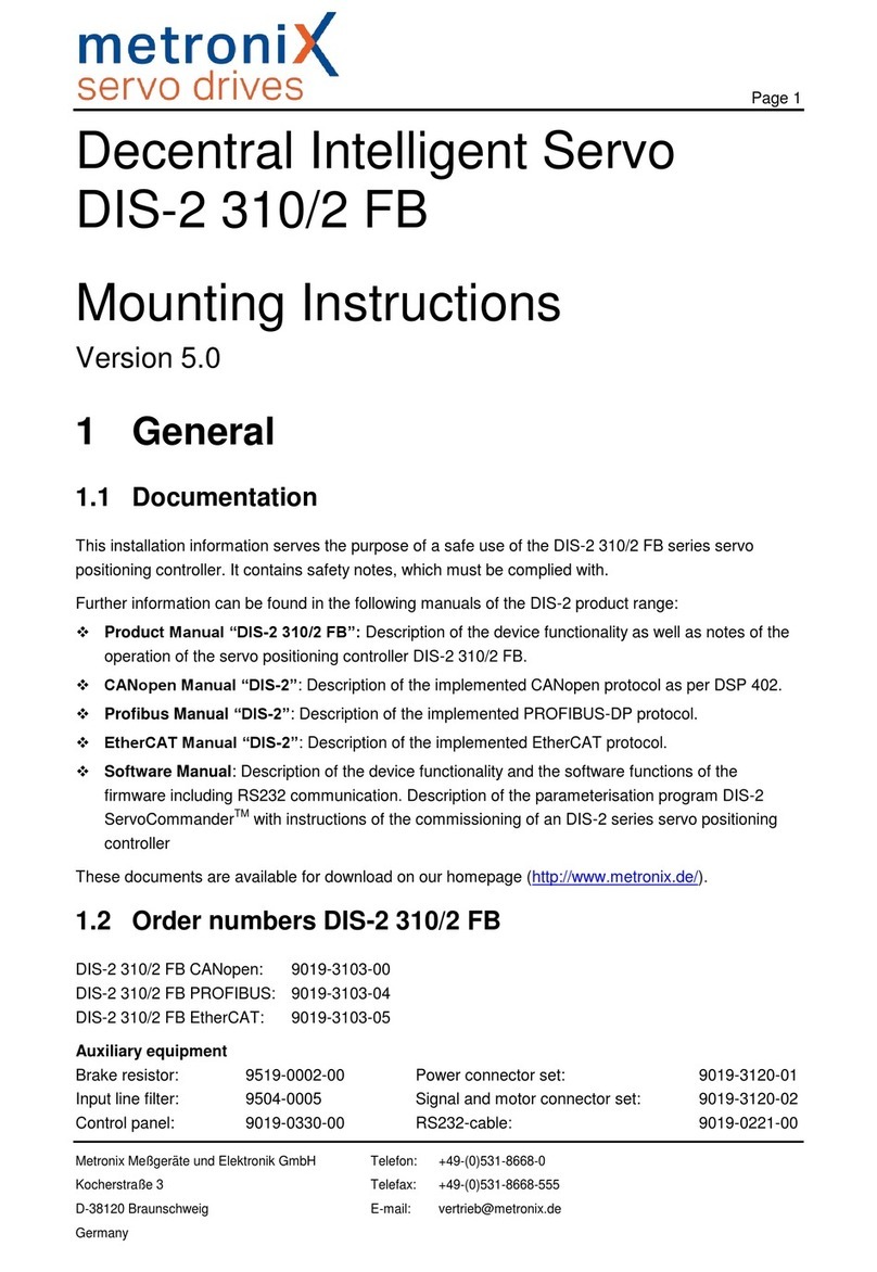
Metronix DIS-2 310/2 FB FS STO User manual
Metronix
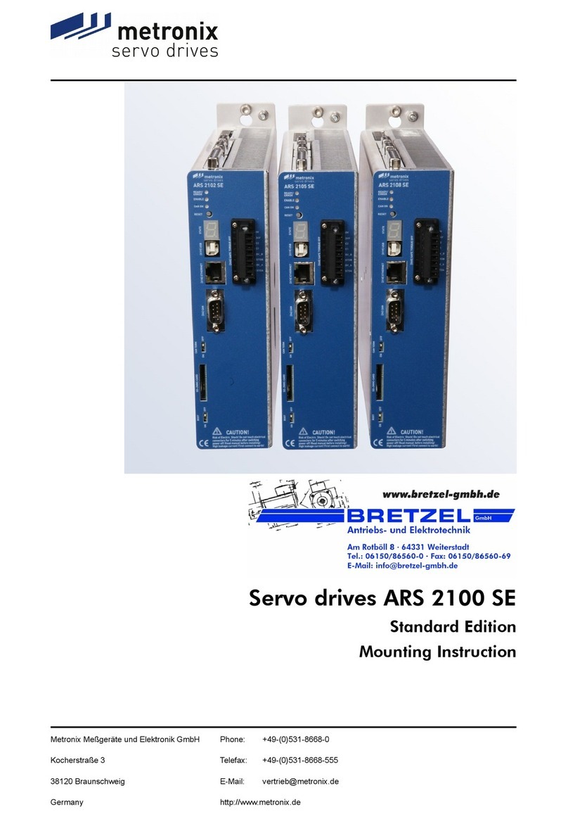
Metronix ARS 2100 SE User guide

Metronix
Metronix APM-SA Series User manual
Metronix
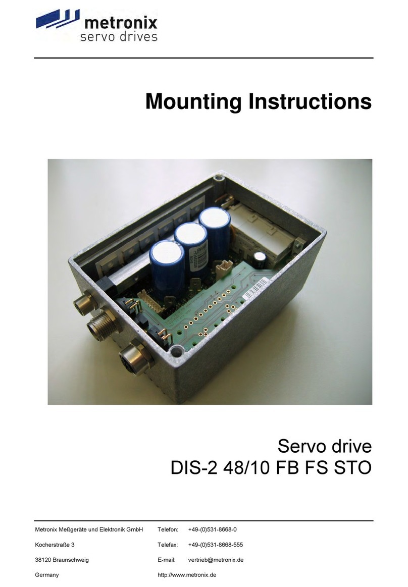
Metronix DIS-2 48/10 FB FS STO User manual
Metronix
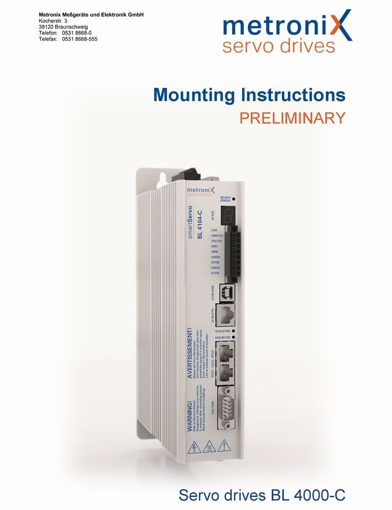
Metronix smartServo BL 4000-C Series User manual
Metronix
Metronix ARS 2320 User manual
Metronix
Metronix ARS 2100 SE User manual
