TECH ST-77 Assembly instructions

ST – 77
Manual Guide

ST-77 – Manual Guide
TECH
Declaration of compatibility number 3/2004
We, TECH company, ul St Batorego 14, 34-120 Andrychów, declare with
the full responsibilty, that thermoregulator ST-77 230V, 50Hz produced
by our company complies with the demands of the Decree of the Ministry
of Economy, Employment and Social Politics (Dz U 03 49 414) from 12th
March 2003, implementing decisions of Low Voltage Directiv
73/23/EWG, and the Decree of the Ministry of Infrastructure (Dz U
03 90 848) from 2nd February 2003 impplementing decisions of EMC
Directiv 89/336/EWG
Harmonised standards PN-EN 60730-2-1:2002 were used to evaluate
compatibility
For the first time, the product was marked CE on 4th May 2004
Co-owners:
Paweł Jura, Janusz Master
Andrychów, 4th May 2004
- 2 -

TECH
CAUTION!
LIVE ELECTRIC DEVICE!
Before doing anything demanding current
supply (e g connection of wires,
installation of the device, etc ) one must
make sure that the regulator is not live!
The device should be intstalled by a person
with adequate electrical training and
certificates
Before starting the programmer one
should measure the effectiveness of
neutralization of electric engines, boiler, as
well as measure insulation of electric
wiring
- 3 -

ST-77 – Manual Guide
I. Description
Temperature regulator ST-77 is to be used with the Central Heating
Boilers It steers the pump of water circulation, the pump of Consumed
Hot Water (C H W ), the fan and the fuel feeder
●if the temperature of the boiler is lower than the Set Temperature, the
regulator is in a cycle of ork in which the fan works all the time; fuel
feeder working time is set up by the user (both the time of work and
the time of break have to be set up)
●if the themperatre of the boiler is equal or higher than the Set
Temperature, the regulator is in the cycle of support
- 4 -
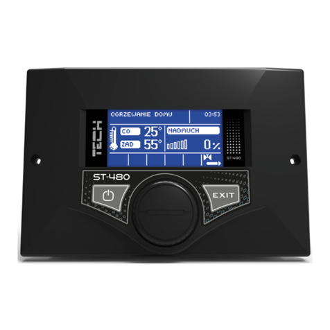
Button MINUS
Button that allows
for escaping from the
menu and cancelling
the set up
Button that allows
for entering menu
and confirming the
set up
Button PLUS

TECH
II. Functions of the regulator
This chapter describes the functions of the regulator, the way of
changing the set up, and the way of using the menu
II.a) Main page
During the normal work of the regulator, the LCD projector shows
the main page, which gives the following information:
●The temperature of the boiler (CH)
●The set temperature
This screen enables quick change of the Set temperature by using
buttons PLUS and MINUS Pressing button MENU takes user to the first
level of the menu The projector shows first two lines of the menu One
can move in ech of the menus by using buttons PLUS and MINUS
Pressing button MENU takes the user to the further menu or starts the
chosen option ESCAPE takes the user back to the previous menu In the
case of projecting the main page, pressing (and holding) the button
ESCAPE will show the screen informing of turning the pump of consumed
hot water on or off
II.b) Manual work
- 5 -
62oc 72oc
CH SetTemp
Manual Work
WorkingTimeoffee
62oc 72oc
CH SetTemp
Feeder
Fan

ST-77 – Manual Guide
For the user’s comfort, the regulator was equipped with the Manual
Work function This function allows for turning each element of the
system on and off regardless of the other elements
Pressing button MENU starts the fuel feeder The feeder works until
button MENU is pressed again
Pressing MENU turns the fan on/off
Pressing button MENU turns the water pump on/off
Pressing button MENU turns the CHW pump (boiler pump) on/off
Pressing button MENU turns alarm on/off (see also the chapter
Alarm)
- 6 -
Feeder
Fan
Feeder
Fan
Fan
Pump
CHW Pump
Alarm
CH Pump
CHW Pump

TECH
II.c) Working time
This option allows for setting up the working time of the
fuel feeder Working time set up depends on the type used fuel as well as
on the type of the boiler
II.d) Break Time
Button Feeder Break Time is for setting break in the feeder working
time The break has to be adequate to the type of fuel used in the boiler
Wrong set up of both the feeder working time as well as the feeder break
time may cause faults in the work of the boiler, i e coal may not get
burnt in full or the boiler may not reach the set temperature Choosing
the right times allows the boiler to work well
II.e) Temperature of turning CH and CHW pumps on.
- 7 -
62oc 72oc
CH Set Temp
12 min 3 sek
Feeder BreakTime
Feeder Work Time
Feeder BreakTime
62oc 72oc
CH Set Temp
62oc 72oc
CH Set Temp
Feeder Work Time
Feeder BreakTime
min 3 sek
Feeder Work Time

ST-77 – Manual Guide
This function allows to set up the temperature of turning CH and
CHW Pumps on (it’s the temperature measured in the boiler) Below the
set temperature both pumps don’t work, above the set temperature both
pumps are turned on, but they work depending on the settings, i e they
are turned on alternately (see function priority pump or constant CH
pump)
II.f) CHW Hysteresis
This function allows for setting up the hysteresis of the set
temperature in the boiler It is a difference between the set temperature
(so the temperature the user wants to have in the boiler) and the
temperature that is in the boiler at a certain time (e g if the set
temperature equals 55 C and hysteresis equals 5 C: after reaching the
set temperature, i e 55 C, the CHW pump turns itself off and the CH
pump turns itself on; the CHW pump will turn itself on again after the
temperature drops to 50 C)
II.g) Hysteresis
- 8 -
Feeder BreakTime
CH and CHW Pump
35 oc
CH and CHW Pump
62oc 72oc
CH Set Temp
62oc 72oc
CH . Set Temp
CH and CHW Pump
CHW Hysteresis
1 oc
CHW Hysteresis

TECH
This function allows for setting up hysteresis of the set temperature
It is the difference between the output temperature in the support cycle,
and the temperature needed for return to the cycle of work (e g when
set temperature equals 60 C, and hysteresis equals 3 C, the boiler will
enter the cycle of support after reaching temperature of 60 C, whereas it
will return to the cycle of work when the temparture drops to 57 C)
II.h) an Speed
This function steers the speed of work of the fan It can be regulated
between speed 1 nad speed 6 (it can be said that these are the fan’s
gears) The higher the gear the faster the fan works Gear 1 is fan’s
minimum speed and gear 6 is fan’s maximum speed
Changes between gears can be introduced by pressing buttons PLUS or
MINUS The fan always starts working with the maximum speed –
thanks to this set up it is possible to turn the fan on even when the
engine is dusted
II.i) Activation of CHW Pump – Boiler’s priority
Activation of CHW pump (by pressing button ON), will make
regulator work in the process called Boiler’s priority In this process CHW
pump (boiler’s pump) is on until it reaches the set temperature, then it is
automatically turned off and the CH pump is activated
- 9 -
3
Fan Speed
Hysteresis
Fan Speed
62oc 72oc
CH Set Temp
CHW Hysteresis
Hysteresis
2oC
Hysteresis

ST-77 – Manual Guide
To change the set temperature of CHW pump, press button Escape-
wyjscie (hold it for a few seconds) and the screen will project boiler’s set
temperature and boilers actual temperature
To change the temperature range use buttons PLUS or MINUS
After a few seconds the projector goes back to its initial stage After
reaching the boiler’s set temperature, CHW pump is turned off and the
CH pump is turned on
In this process, the work of the fan and the feeder is limited to the
temperature of 62 degrees in the boiler It prevents the boiler from over-
heating This state of the boiler will be supported until it reaches the the
set temperature If the set temperature is reached, CHW pump is turned
off and the CH pump is turned on
CH pump continues working until the temperature in the boiler drops
below the set temperature Then CH pump is turned off and the CHW
pump is turned on
The process of ‘boiler’s priority’ makes the boiler heat the consumed hot
water first and only afterwards heat the water in radiators
Caution! Non-return valves should be installed on the CHW and CH
pumps’ circulations The valve installed on the CHW pump prevents from
taking the hot water out of the boiler The valve installed on CH pump
does not let the hot water that heats the boiler be used in the house
II.j) Room regulator
- 10 -
62oc 72oc
CH Set Temp
CHW Pump
CHW Pump
62oc 72oc
CH Set Temp
Fan Speed
CHW Pump
off
on

TECH
Room regulator can be adjusted to the regulator ST-77 Then it has
a higher priority The feeder and the fan work until the temperature set
on the room regulator is reached However, the work of the boiler is
limited by the temperature set on the regulator installed on the boiler
II.k) Alarm
To set up the activation time for the alarm of temperature use
buttons PLUS/MINUS To save the set time press button MENU This
function is activated only in the cycle of ork (i e when the temparuter
of the boiler is lower than the set temperature If the temperature of the
boiler does not increase in the time set by the user, alarm is activated:
the feeder and the fan are automatically turned off, (water pump is
turned on/off independenty), and the sound signalling is turned on The
screen projects an adequate message (see chapter Safety Protection)
II.l) unction of the constant CH pump
Activating this function of the regulator starts parallel work of the
pumps above the set temperature (see sub-chapter: Temperature of
turning CH and CHW pumps on): CH pump works all the time and the
CHW pump is turned off after reaching the set on the boiler temperature
Caution! It is important to install a three-way valve or another mixing
valve that would keep different temperature in the boiler from the one in
the house
- 11 -
off
on
1 gdz 1 min
ALARM
62oc 72oc
CH Set Temp
Room Regulator
ALARM

ST-77 – Manual Guide
II.m) Summer function
After activating this function the CH pump is turned off and the CHW
pump is turned on above the set temperature (see sub-chapter:
Temperature of turning CH and CHW pumps on) It is turned off after
reaching the temperature set on the boiler CHW pump is turned on again
after the temperature on the boiler drops 10 degrees
II.n) Burning
- 12 -
on
off
62oc 72oc
CH Set Temp
alarm
Constant CH Pump
yes
no
62oc 72oc
CH Set Temp
Constant CH Pump
Summer Function
Burning Break
Produce. Settings
62oc 72oc
CH Set Temp

TECH
This function allows for regulating the work of the boiler during the
support cycle It prevents the boiler from burning out when the
temperature of the boiler is above the set temperature.
In this function the break time of the feeder and the fan need to be set
up After the set time the feeder and the fan are turned on for the time
set by the producer of the boiler The time of work of the fan and the
feeder can be changed in the service functions The time of break of
burning should be set up depending on the type of the fuel and the boiler
Caution! Wrong set up of the described functions may cause
constant increase in the temperature! The time of break of
burning shouldn’t be too short.
II.o) Producer’s settings
The regualtor is preliminarily configurated for work However, it
should be adjusted to the individual needs of the user It is possible to
return to the Producer’s settings at any time
III. Safety Protection
In order to provide the maximum of safe and faultless work, the
regulator is equipped in a variety of safety protections Alarm activates
sound signalling and the screen projects an adequate message The
regulator will start working again after pressing button MENU.
- 13 -
62oc 72oc
CH . Set Temp
no
yes
Feeder and Fan
Produce Settings

ST-77 – Manual Guide
III.a) Temperature Alarm
This protection activates only in the cycle of ork (i e when the
temperature of the boiler is lower than the Set Temperature) If the
temperature does not increase in the time set by the user (see sub-
chapter: Alarm) , alarm is activated: the feeder and the fan are
automatically turned off, (water pump is turned on/off independenty),
and the sound signalling is turned on The screen projects an adequate
message:
The regulator expects the button MENU to be pressed, after which
the alarm is turned off The regulator returns to the previously set
process of work
III.b) Thermal Protections
It is an additional bimetallic mini-sensor (installed next to the
boiler’s sensor) which cuts off the feeder and fan’s exits in the case of
reaching and exceeding the temperature of 90 degrees It prevents water
which is in the system from boiling in case of the failure in the work of
the regulator
III.c) Automatic Sensor Control
Alarm is activated in the case of failure in the work of the sensors of
CH or CHW temperature or in the work of worm Adequate message
about the failure is also projected on the screen, e g :
The feeder nad the fan are turned off The pump is turned on
independently of the actual temperature The regulator i waiting for the
button MENU to be pressed after which alarm is turned off and the
regulator starts working again
- 14 -
A L A R M
NOINCREASE INTEMP
A L A R M
SENSOR FAILURE

TECH
III.d) Protection against boiling water in the boiler
This protection prevents high temperature to appear in the
boiler (only during using the function: boiler’s priority) When the
set on the boiler tempertaure equals 55 degrees Celsius and the actual
temperature in the boiler equals 62 C, the feeder and the fan are turned
off When the temperature increases to 80 C, CH pump is turned on
When the temperature still continues to increase, when it reaches 85 C
alarm is turned on Described situation may appear when boiler is
damaged or faulty, the sensor is installed in the wrong way, or the pump
has a fault However, if the temperature decreases, when it drops to 60 C
the regulator will turn the feeder and the fan on and it will work until
reaching the set on the boiler temperature
III.e) Temperature Safety Protections
The regulator is equipped in an additional protection in the case of
faulty bimetallic sensor: alarm is turned on and an adequate message is
projected on the screen after the tempertaure of 95 degrees is exceeded:
III.f) uel eeder Protection
The worm in the fuel feeder is equipped in an additional sensor
measuring temperature Alarm is turned on when the temperature
increasea significantly (above 65 C): the feeder is turned on for 10
minutes in order to move the fuel to the combustion chamber The sensor
in the worm prevents the fuel from burning in the basket
III.g) use
The regulator is equipped in tubular fuse-element WT 6 3A, that
protects the system
- 15 -
A LA R M
BasketSen Failure
A L A R M
TOO HIGH TEMP

ST-77 – Manual Guide
IV. Maintenance
It is important that the technical condition of the cabling is checked
before and during the heating period Additional actions that need to be
taken in the same time are: check the fastening of the regulator, clean it
from dust and other contamination; measure the effectiveness of the
engines earthing (pump, CHW pump, fan and feeder)
L.p. Specification Units
1 Current Supply V 230V/50Hz +/-10%
2 Power Consumption W 4
3 Ambinet Temperature OC0±40
4 Load of the Circulating Pump Exit A 1
5 Range of Temperature Measuring OC0±90
6 Measuring Error OC 1
7 Range of Set Temperatures OC0±85
8 Temperature Resistance of the Sensor OC- 25 to 100
V. Repairs
All faults should be reported to:
TECH S C
34-120 Andrychów ul St Batorego 14
tel 33 8705105 , 33 8759380
- 16 -

TECH
VI. Installation
Caution! Installation should be performed by a person with
adequate training and certificates The device MUST NOT BE LIVE at the
time of installation (one MUST make sure that the plug is
DISCONNECTED from the power network)
CAUTION! Wrong installation of the cabling may damage
the regulator.
The regulator cannot work in the closed system of the central
heating Safety valves, pressure valves and surge tank that protect the
boiler from boiling of water in the central heating system must be
installed
VI.a) Diagram of the regulator’s cabling installation
Additional attention has to be paid during installation of the regulator’s
cabling It is very important to install the earthing wiring in the right
way
- 17 -
PE
N
L
FUSE 6 3A
~
Transmiter
230V AC
Fan
~
Transmiter
230V AC
CH Pump
~
Transmiter
230V AC
Feeder
~
Transmiter
230V AC
CHW Pump
Room
regulator
Thermical
Fuse
Boiler s
Sensor
Worm s
Sensor
Boiler s
Sensor
Feeder
Fan
CH
Pump
CHW
Pump
Network
L L L L
N N N N NL
1 2 3 4 5 6
7 8 9 10 11 12
Reed Relay

Spis treści
I Description 4
II Functions of the regulator 5
II a) Main page 5
II b) Manual work 5
II c) Working time 7
II d) Break Time 7
II e) Temperature of turning CH and CHW pumps on 7
II f) CHW Hysteresis 8
II g) Hysteresis 8
II h) Fan Speed 9
II i) Activation of CHW Pump – Boiler’s priority 9
II j) Room regulator 10
II k) Alarm 11
II l) Function of the constant CH pump 11
II m) Summer function 12
II n) Burning 12
II o) Producer’s settings 13
III Safety Protection 13
III a) Temperature Alarm 14
III b) Thermal Protections 14
III c) Automatic Sensor Control 14
III d) Protection against boiling water in the boiler 15
III e) Temperature Safety Protections 15
III f) Fuel Feeder Protection 15
III g) Fuse 15
IV Maintenance 16
V Repairs 16
VI Installation 17
VI a) Diagram of the regulator’s cabling installation 17

GWARANCJA
TECH company gaurantees correct functioning of the product
for the period of 30 months from the date of purchase The
company obliges itself to repair any faults that are producer’s fault,
free of charge In this case the device has to be delivered to the
place of purchase It is the user’s responsiblity to cover the costs of
such delivery
This guarantee does not include faults that occurred due to the
wrong use of the product, or those that are the user’s fault;
mechanical faults or those that appeared after atmospherical
discharge, overvoltage or shorting
Without the attached receipt of purchase, date of purchase, date of
delivery or signatures, this guarantee is not valid
This guarantee is the only document that gives the user rights to
repairs free of charge
The producer does not issue duplicates of this guarantee in case of
its loosing or damaging
Delivery Date Seller’s Stamp Date of Purchase

Notes:
Table of contents
Other TECH Controllers manuals
Popular Controllers manuals by other brands
Watts
Watts valpes VRX Series Installation and operation manual
Gebruder Heyl Analysentechnik
Gebruder Heyl Analysentechnik Testomat 808 quick start guide

Pego
Pego 200NDINFSC User and maintenance manual

Lennox
Lennox PRODIGY M2 Installation & setup guide

MKS
MKS MC20A manual
TREND
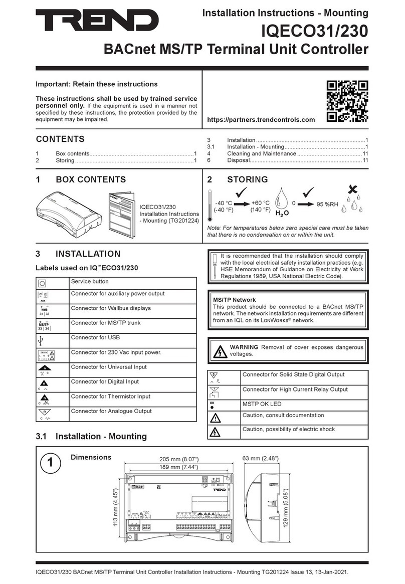
TREND IQECO31/230 installation instructions
