Enginuity SIPP-600 User manual
SIPP-600, Feb 2012
001-01-000055 Rev. 000
©2012 Enginuity Communications, Inc. Page 1 of 7
Service Interface Protection Panel
Model SIPP-600
SECTION PAGE #
1. OVERVIEW..............................................................1
2. APPLICATION.........................................................1
3. DESCRIPTION........................................................2
4. INSTALLATION.......................................................3
5. TESTING & TROUBLESHOOTING ......................5
6. CUSTOMER SERVICE ..........................................5
7. WARRANTY AND REPAIRS.................................5
8. SPECIFICATIONS ..................................................6
9. ORDERING GUIDE................................................7
1. OVERVIEW
The Service Interface Protection Panel (SIPP), Model
SIPP-600, is a modular and easy to configure interface
that protects network transmission equipment exposed to
outside plant facilities. Advanced technology in the SIPP
provides greater protection to network equipment than
conventional methods. Applications include central
offices, CEVs, and outside plant cabinets - wherever
protection from lightningsurges and AC power faults is
needed.
The base SIPP-600 model is a 6-slot chassis that accepts
plug-in modules to terminate and protect dry-loop
Ethernet, T1/E1, or DS3 services. A fiber interface
module (without protection) is also available, allowing all
high-speed services to be groomed through a single
access panel. A choice of connector configurations
provides added flexibility and utility. The SIPP can be
installed in cabinet or wall mounted.
Document Status
This version of the document (Rev. 000) supersedes all
preliminary (Rev. Pxx) versions.
Product Features
Carrier-class interface for high-speed services:
oEthernet 10/100 or GigE (RJ45)
oT1/E1 (RJ48)
oDS3 (Coax)
Enhanced protection against lightning and AC
power faults
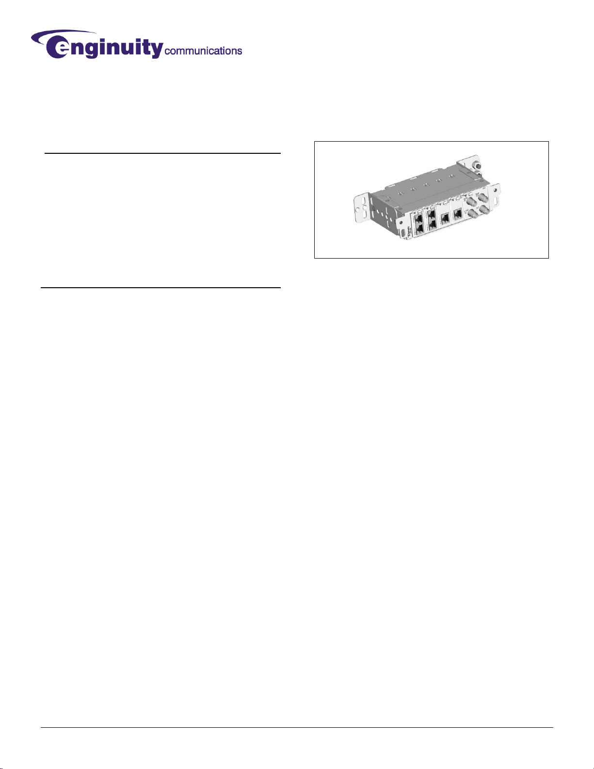
Up to 6 circuits in a compact 1RU chassis
Figure 1. SIPP-600 with modules installed
Supports multiple wall mount configurations
Plug-in flexibility and convenience
Choice of front-only or front and rear access
Keystone module for fiber or unexposed cable
Heavy duty, stainless steel construction
Tested to TelcordiaGR-974, GR-3108, and NEBS
requirements
Operating temperature range of -40oC to +70oC
2. APPLICATION
Multiplexers, switches and other network elements that
are connected to outside plant facilities require protection
from excess voltage or current that could cause damage
to equipment or injure personnel.
A common method is to install voltage-limiting primary
protectors on network ports and a separate service panel
for connection to outdoor facilities. The shortcomings of
this approach are: 1) voltage limiting alone may not
adequatelyprotect some types of network equipment,
2) wiring to separate protector blocks and service panels
is space consuming and cumbersome, and 3)many
applications require fuse links to prevent risk of fire,
shock, or potential damage to the service panel.
The SIPP resolves these issues by combining service
panel convenience with advanced protection of personnel
and equipment (seeFigure 2). The integrated solution
meetsrigorous telecom network standards, simplifies
wiring, and saves valuable space.
001-01-000055 Rev. 000 Page 2 of 7
TWISTED PAIR
CAT5/CAT6
Network
Equipment
Customer
A
Customer
B
Customer
C
FIBER Customer
D
COAX
T1
DS3
Ethernet
Fiber
SIPP
Service
Interface
+
Primary
Protection
+
High-Speed
CurrentLimiter
BUILDING,HUT, ORCABINET
Figure 2. SIPP application
The versatility of the SIPP makes it suitable for any
combination of Ethernet, T1/E1, DS3, or fiber services in
central offices, CEVs, or outside plant cabinets.
Orderable options allow for front-only or front and rear
access to connectors.
NOTE: For dry-loop service only (no DC voltage).
3. DESCRIPTION
The base SIPP-600 model is a 6-slot chassis, 1RU high,
with adjustable brackets for a variety of wall mount
configurations. The chassis is constructed of heavy-
gauge stainless steel and accommodates up to six plug-
in modules, as described below. Model SIPP-600C
includes a removable cable cover to prevent tampering
with front-side network equipment connections.
Plug-in Modules
Service Protection Modules (SPM) connect to copper
facilities to protect Ethernet, DS3, or T1/E1 network
equipment against lightning surges and AC power faults.
Modules are available with front-only or front and rear
connectors, and optional monitor jacks. Each SPM
occupies one or two slots in a SIPP chassis, depending
on the chosen jack configuration.
Figure 3. Example Service Protection Modules
Fiber services or copper services that do not require
protection can beconnected through a Modular Interface
Panel (MIP), shown in Figure 4. The MIP module
occupies four slots in a SIPP chassis and provides four
Keystone slots for snap-in couplers that connect network
equipment to facilities.
Please refer to the Ordering Guide at the end of this
documentfor a list of plug-in modules and their
descriptions.
Figure 4. MIP with SC fiber couplers installed
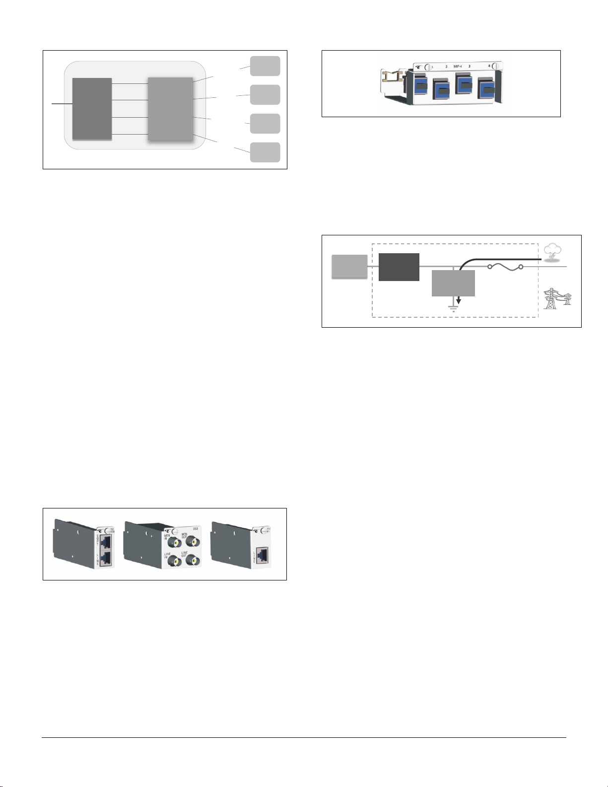
Coordinated Protection
The Service Protection Modules combine current limiting,
voltage limiting (gas discharge tube), and fusing to
prevent lightning and AC surges from damaging network
equipment.Figure 5 shows the placement of these
protection elements within the SPM.
EXPOSED
FACILITY
HIGH-SPEED
CURRENT
LIMITER
SURGEENERGY
NETWORK
EQUIPMENT
SPM
GAS
DISCHARGE
TUBE
SURGE
TOLERANT
FUSE
Figure 5. SPM block diagram
The fast-reacting current limiter blocks transients by
switching to a highresistance state, at which point the
gas tube diverts surge energy to ground. The
combination of current and voltage limiting blocks more
energy than can be achieved by voltage clamping alone.
Within one microsecond, the current let through toward
network equipment is reduced to less than 1 mA (0.1V
into a 100Ωload). After the surge clears, the current
limiter returns to a low series resistance and the gas tube
returns to high bridging resistance.
Fail Safe Operation
Fusing within the SPM provides an alternative to
installation of external fuse links. In the event of an
extreme lightning surge or high AC exposure, SPMfuses
opens to prevent hazardous damage to connectors or
cabling. The fuses are surge tolerant and remain
transparent to moderate strikes.
In addition, all SPM gas tubes include a fail-short
mechanism that prevents thermal overload under AC
conditions. The feature creates a mechanical short to
ground and only operates if prolonged AC energy exists
that could otherwise create a fire hazard.
Activation of a fuse or fail-short mechanism requires the
SPM to be replaced.

001-01-000055 Rev. 000 Page 3 of 7
4. INSTALLATION
Chassis Installation
The SIPP-600 chassis is 1RU in height (1.75 inches) with
adjustable mounting brackets that support a variety of
wall mounted configurations (Figure 6).
Figure 6. Mounting configurations
To install the SIPP-600 on a wall or other surface:
1) Align the holes of a mounting bracket with holes on
the side of thechassis in the desired position. The
brackets can be positioned with the flanges toward
the rear, top, or bottom of the chassis.
2) Insert two (2) of the included 8-32 x 3/8” machine
screws through the round holes of the bracket and
tighten them firmly.
3) Repeat steps 1 and 2 with the second bracket on the
oppositeside of the chassis. Ensure that the
positions of the brackets are symmetrical.
4) Attach the panel assembly to a suitablesurface with
four (4) fasteners (not included), two for each bracket.
Besure to use the appropriate fastener type, and
anchors if necessary, to securely support the panel.
For outside plant applications, the SIPP assemblymust
be installed in a cabinet that complies with Telcordia
GR-487 requirements.
Chassis Grounding
CAUTION: Protection requires the use of appropriate
grounding practices in order to function properly. The SIPP
chassis and associated equipment should be connected to a
single common ground point. Wiring must conform to
applicable electrical codes and standards.
To ground the SIPP-600 chassis:
1) Choose an appropriatelysized ground lug to fit the
dual ground posts on the mounting bracket of the
chassis, shown in Figure 7. The studs are 1/4”
diameter with 5/8” center-to-center spacing.
2) Fasten the ground lugsecurely to thestuds with the
included lock washers and 1/4”–20 hex nuts.
3) Attach one end of a #6 AWG ground wire to the
ground lug.
4) Attach the other end of the #6 AWG ground wire to
the nearest qualified ground (impedance of 1 ohm or
less) via the shortest and most direct path, avoiding
sharp turns.
Figure 7. Chassis ground connector
WARNING
To avoid possible electric shock or personal injury,
follow these guidelines:
1) Do not install, troubleshoot, or conduct maintenance on
the SIPP-600 or associated SPM modules during
lightning or thunderstorm activity.
2) This equipment provides primary protection and
requires use of appropriate installation practices.
Only qualified and trained personnel should install or
maintain these products.
Complete the installation of the protection equipment
BEFORE connecting outside cable facilities.
A separate primary protector should not be installed
in conjunction with this equipment.
Suitable cabling must be used for all connections.
3) Protection requires the use of appropriate grounding
practices in order to function properly. The SIPP chassis
and associated equipment should be connected to a
single common ground point. Wiring must conform to
applicable electrical codes and standards.
Ground posts
001-01-000055 Rev. 000 Page 4 of 7
SIPP-600C Cable Cover
Model SIPP-600C includes a cable cover (Figure 8) that
needs to be removed in order to install or remove
modules. The cable cover prevents tampering with front-
side connections to network equipment after the modules
and cables are installed. The cover is fastened to the
chassis with two (2) spring-loaded Phillips screws.
Figure 8. SIPP-600C with cable cover
SPM Installation
NOTE: Primary protectors shall be installed in
accordance with the applicable requirements of National
Electric Code ANSI/NFPA-70, Article 800 Section 800.50.
Service Protection Modules can be placed in any order or
combination in available positions of the SIPP-600
chassis. Each SPM occupies one or two positions,
depending on its function.
To install a module, insert it into the front of the chassis
and slide it back slowly through the card guides. After fully
seating the module, tighten the screw on the front of the
unit to ensure proper grounding of its front panel to the
chassis frame.
SPM Network Connections
For SPM-XX-R modules, connect network equipment to
the jack(s) on the rear of the module.
NOTE: Installations with limited rear access may require
cables to be fed through the chassis, from back to front,
and attached to the module before inserting it into the
mounting. Be sure to provide adequate cable slack.
For SPM-XX-F modules, connect network equipment to
the EQPT jack(s) on the front of the module.
SPM Line Connections
Connect the exposed facility to the LINE jack(s) on the
front of the module.
MODULE CONNECTOR
CONNECT TO
Front (EQPT) or rear
Network equipment (protected)
Front (LINE)
Exposed facility (unprotected)
SPM Removal
To remove a protection module, first disconnect cables
from the unit. If access is limited, rear cables can be
disconnected after the module is removed from the
mounting. Loosen the screw on the module’s front panel
and slowly slide the unit forward out of thechassis, being
careful to guide anycables connected to the rear.
MIP-4 Couplers
The MIP-4 module accepts snap-in Keystone style
couplers for fiber, coaxial, or twisted pair terminations that
do not require protection.
NOTE: Couplers are installed or removed from the rear
of the MIP-4 with the module removed from the chassis.
Each coupler is held in place by angled tabs along the top
and bottom of the coupler body. To install a coupler, tilt it
back slightly while inserting it though therectangular
opening, until the lower tab clears thefront of the panel.
Then apply pressure to the upper tab and tilt the coupler
bodyforward until it snaps in place.
To remove a coupler from the MIP-4, apply pressure to
the upper tab while tilting the coupler bodybackward.
After the upper tab is freed, the coupler can be lifted and
removedfrom the opening.
MIP-4 Installation/Connection
The MIP-4 module occupies four slots in the SIPP-600
chassis.
Before installing the MIP-4 module, feed network cables
through the chassis, from back tofront, and connect them
to the rear of the couplers. Then insert the MIP-4 through
the front the chassis and slide it back slowly through the
card guides. After fully seating the module, tighten the
WARNING
When removing a module or its LINE connection:
Visuallyinspect the cable and equipment for damage or
exposed conductors BEFORE making contact.
Use appropriate detection equipment to ensure that no
hazardous voltages or currents are present.
Follow local guidelines for safety.
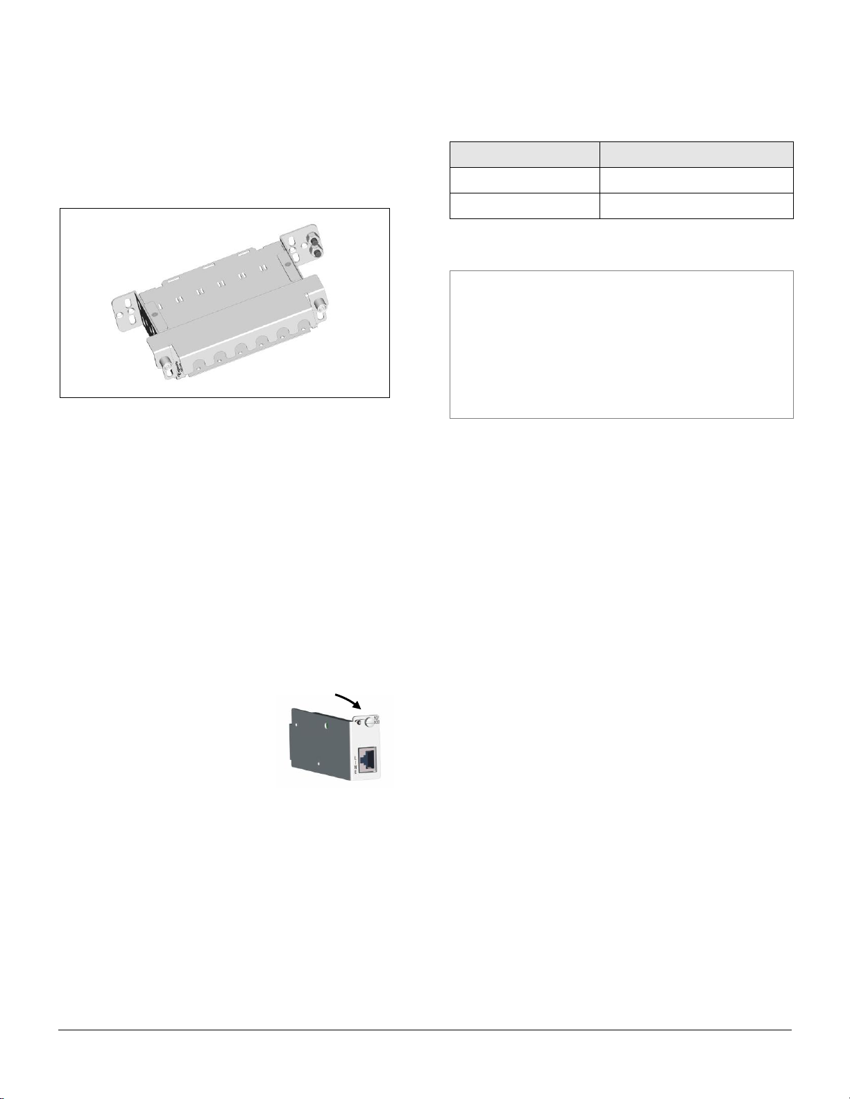
IMPORTANT: The module’s
front panel screw must be
tightened securely to ensure
proper grounding.
Recommended screw torque
is four (4) inch-pounds.

001-01-000055 Rev. 000 Page 5 of 7
screw on the front of the unit to ensure proper grounding
of its front panel to the chassis frame.
Connections can now be made to the front of the installed
couplers.
MIP-4 Removal
To remove the MIP-4 module, first disconnect cables
from the front of each coupler. Then loosen the screw on
the module’s front panel and slowly slide the unit forward
out of the chassis, being careful to guide anycables
connected to the rear. Cables can then be disconnected
from the rear of each coupler.
5. TESTING AND TROUBLESHOOTING
To test through a module toward the protected
equipment,connect test equipment to the LINE jack(s) on
the front of the unit. To test toward the exposed facility,
connect to the equipmentside jack(s)on the front or rear
of the unit(jack location depends on the specific model
being used).
Loss of signal, or more than 1.0 dB insertion loss through
an SPM, indicates that a fail-safe condition has occurred
and that the module needs to bereplaced.
6. CUSTOMER SERVICE
If technical or customer assistance is required, please
contact Enginuity at the following address or phone
number:
Enginuity Communications
1251 Nagel Blvd.
Batavia, Illinois 60510
Toll Free: 1-800-980-3266
Voice: (630) 761-1892
www.enginuitycom.com
7. WARRANTY & REPAIRS
Warranty
Enginuity warrants this product for ten (10) years from
date of purchase.
The Service Protection Modules contain fuses and fail-to-
ground mechanisms to safely protect personnel and
equipment. Operation of these fail-safe mechanisms due
to high voltage or current constitutes normal operation
and replacement under these conditions is not covered
by this warranty.
The warranty does not cover anylosses or damages
resulting from shipment, improper installation, abuse,
modification, or repair byother than Enginuity personnel.
Repair and Return
Enginuity equipment will be repaired or replaced without
cost during the warranty period if the product is defective
for any reason other than abuse, improper use, or
improper installation. Before returning defective
equipment,first request a Return Material Authorization
(RMA) number from Enginuity. Once an RMA number is
obtained, return the unit, freight prepaid, along with a brief
description of the problem, to:
Enginuity Communications
1251 Nagel Blvd.
Batavia, Illinois 60510
ATTN: Repair & Return Dept.
Replacements will be shipped in the fastest manner
consistent with the urgency of the situation. Repair or
replacement of faulty equipment beyond the warranty
period is available for a nominal charge. Contact
Enginuity for details.
IMPORTANT
Follow all instructions and safety warnings in the installation
section of this publication (Section 4) when testing or
troubleshooting this equipment.

001-01-000055 Rev. 000 Page 6 of 7
8. SPECIFICATIONS
Chassis (SIPP-600)
Dimensions
Height: 1.75” / Width: 6.1” (excluding mounting brackets) / Depth: 4.3”
Weight
1.6 pounds
Service Protection Modules
Ethernet 10/100 (SPM-100-XX)
Signal
10Base-T: Manchester Encoding, 10MHz or 100Base-T: MLT-3, 125MHz
Connector
Cat5e RJ45; gel coated contacts
Protected Leads
Pins 1, 2, 3, 6 (Pins 4, 5, 7, 8 grounded)
Ethernet GigE (SPM-1G-XX)
Signal
PAM-5 TC, 125 MHz, 1Gbit/s
Connector
Cat6 RJ45 (shielded); gel coated contacts
Protected Leads
Pins 1 through 8
T1/E1 (SPM-T1-XX)
Signal
T1: AMI B8ZS Encoding, 1.544 MHz, E1: HDB3 Encoding, 2.048 MHz
Connector
RJ48; gel coated contacts
Protected Leads
Pins 1, 2, 4, 5 (Pins 3, 6, 7, 8 grounded)
DS3 (SPM-DS3-XX)
Signal
AMI B3ZS Encoding, 44.736 MHz
Connector
75Ω BNC
Protected Leads
Center (signal)
Common Specifications (applicable to each of the above modules)
Standards
Tested to Telcordia GR-974, GR-1089, GR-3108, and GR-63 requirements
Application
Dry loop (No DC)
Impulse Life Characteristics
±10 A, 10/1000 µs:
> 1500 operations
±100 A, 10/1000 µs:
> 100 operations
AC Life Characteristics
1 A rms, 1 sec:
> 60 operations
10 A rms, 1 sec:
Fuse opens for protection
End of Life Characteristics
±10 A, 10/1000 µs:
> 3000 operations
±100 A, 10/1000 µs:
> 300 operations
Current Limiting
(toward equipment)
Protection turn-on threshold:
180 mA min., 360 mA max.
Time to trigger / Time to fully block
~ 10 nanoseconds / ~ 1 microsecond
Maximum let-through (blocked state):
1 mA (0.1V @ 100 Ω)
Insulation Resistance
> 100 MΩ@ ±50 VDC
Insertion Loss
< 1.0 dB
Series Resistance
< 14 Ω
Capacitance
< 20 pF
Operating Temperature
-40o C to +70o C

001-01-000055 Rev. 000 Page 7 of 7
9. ORDERING GUIDE
Chassis
DESCRIPTION
PART NUMBER
SIPP chassis, 6-slot, wall mountable
SIPP-600
SIPPchassis, 6-slot, wallmountable, with removable cablecover
SIPP-600C
Service Protection Modules
SERVICE
CONNECTOR
TYPE
EQUIPMENT
CONNECTION
LINE
CONNECTION
MONITOR
CONNECTION
CHASSIS
SLOTS
PART NUMBER
10/100 Base-T
RJ45
(Cat5e)
REAR
FRONT
N/A
1
SPM-100-R
FRONT
FRONT
N/A
1
SPM-100-F
1G (GigE)
RJ45
(Cat6/shielded)
REAR
FRONT
N/A
1
SPM-1G-R
T1/E1
RJ48C
REAR
FRONT
N/A
1
SPM-T1-R
REAR
FRONT
FRONT
1
SPM-T1-RM
FRONT
FRONT
N/A
1
SPM-T1-F
FRONT
FRONT
FRONT
2
SPM-T1-FM
DS3
BNC Coax
REAR
FRONT
N/A
2
SPM-DS3-R
REAR
FRONT
FRONT
2
SPM-DS3-RM
FRONT
FRONT
N/A
2
SPM-DS3-F
Accessory Panels
DESCRIPTION
CHASSIS
SLOTS
PART NUMBER
Keystone coupler panel with (4) blank inserts installed
4
MIP-4
Keystone coupler panel with (4) SC fiber couplers installed
4
MIP-4SC
Blank cover for empty module slot
1
BP1-1
Cable Management Accessories
DESCRIPTION
PART NUMBER
Universal D-Ring, right or left rail mounted, 1RU
DRNG-U-1
Table of contents
Other Enginuity Protection Device manuals


