Sola HD STV100K Series User manual
Surge Protective Devices
STV100K Series
Instruction Manual


While every precaution has been taken to ensure accuracy and completeness in this manual, EGS Electrical Group, LLC. assumes no responsibility,
and disclaims all liability for damages resulting from use of this information or for any errors or omissions. The SolaHD and Emerson logos are regis-
tered in the U.S. Patent and Trademark Ofce. All other product or service names are the property of their registered owners. ©2011 EGS Electrical
Group, LLC. All rights reserved. Specications are subject to change without notice.
Contents
1.0 Installation................................................................................................... 4
1.1 Environment ........................................................................................................... 4
1.2 Mounting ................................................................................................................ 4
1.3 Proper Connection of SPDs ................................................................................... 4
1.4 Mechanical Dimensions ......................................................................................... 5
1.5 Voltage Protection Ratings (VPRs) ........................................................................ 5
1.6 Circuit Ampacity Limitations ................................................................................... 5
1.7 Wire Sizing/Routing ............................................................................................... 5
1.8 Wiring Connections ................................................................................................ 6
1.9 Applying Power ...................................................................................................... 6
2.0 Troubleshooting.......................................................................................... 8
3.0 Registration&Warranty............................................................................. 8
3.1 Product Registration .............................................................................................. 8
3.2 Warranty Information ............................................................................................. 8
4.0 Specications............................................................................................. 9
STV100K Series Instruction Manual • 4
1.0 Installation
The SolaHD STV100K Series Surge Protective Device is a high-quality, high-
energy surge current diversion system designed to protect sensitive equipment
from damaging transient voltage surges resulting from load switching, lightning
strikes, and other sources.
The installer should perform the following steps to ensure a quality installation.
Please read all instructions before starting the installation of this product. These
instructions do not replace national or local electrical codes. Check applicable
codes to ensure compliance.
!DANGER!Onlyqualiedpersonnelshouldinstallorservicethissystem.Elec-
tricalsafetyprecautionsmustbefollowedwheninstallingorservicingthisequipment.
Topreventriskofelectricalshock,turnoffandlockoutallpowersourcestotheunit
beforemakingelectricalconnectionsorservicing.
1.1Environment
The unit is designed for operation indoors in an ambient temperature range of
-40°C to +60°C (-40°F to +140°F), with a relative humidity of 0% to 95% non-
condensing.
The unit is provided in a metallic industrial enclosure. Do not install in areas with
excessive dust, corrosive vapors, ammable materials, or explosive atmospheres.
1.2Mounting
Mount the unit as close as possible to the service panel. For best performance,
the unit should be positioned so that the length of the wiring to the surge protec-
tive device (SPD) is minimized.
1.3ProperConnectionofSPDs
Type 2 SPDs shall be installed as dened in the National Electric Code (NEC)
2011 Edition as follows:
285.24Type2SPDs(TVSSs)
Type 2 SPDs (TVSSs) shall be installed in accordance with 285.24 (A) through (C).
(A)Service-SuppliedBuildingorStructure.Type 2 SPDs (TVSSs) shall be
connected anywhere on the load side of a service disconnect overcurrent device
required in 230.91, unless installed in accordance with 230.82(8).
(B)Feeder-SuppliedBuildingorStructure. Type 2 SPDs (TVSSs) shall be
connected at the building or structure anywhere on the load side of the rst over-
current device at the building or structure.
(C)SeparatelyDerivedSystem. The SPD (TVSS) shall be connected on the
load side of the rst overcurrent device in a separately derived system.
STV100K Series Instruction Manual • 5
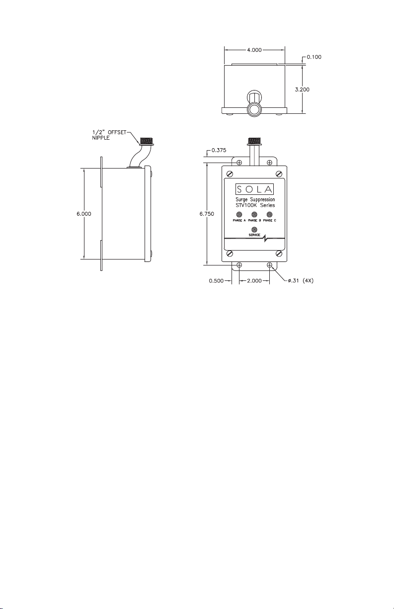
1.4MechanicalDimensions
Figure 1: Mechanical Dimensions (in.)
Unit shown is a three-phase wye
1.5VoltageProtectionRatings(VPRs)
To maintain the voltage protection ratings marked on these products, as obtained
by Underwriters Laboratories, Inc. in accordance with ANSI/UL 1449, 3rd edition,
the Standard for Safety, Surge Protective Devices (SPDs), #12 AWG wire must
be utilized to connect the STV100K Series to your facility’s power grid. Connec-
tions made with conductors other that #12 AWG may result in different VPRs.
1.6CircuitAmpacityLimitations
This device has been investigated by Underwriters Laboratories, Inc. to with-
stand, without exposing live circuits or components on power sources, a voltage
of two times (2x) the device’s ratings, and fault currents of up to 65,000 AIC, as
described in ANSI/UL 1449, 3rd edition, the Standard for Safety, Surge Protective
Devices (SPDs).
1.7WireSizing/Routing
Phase, N, and GND wires are #12 AWG. NO, NC, and COM wires are #18 AWG.
To reduce the wiring impedance to surge currents, we recommend the phase,
neutral (if required), and ground conductors to be twisted together and routed in
the same raceway (conduit). Avoid any sharp bends in the conductors. All wiring
must comply with the National Electrical Code (NEC) and applicable local codes.

STV100K Series Instruction Manual • 6
1.8WiringConnections
Before making connections to the unit, verify that
the unit model number and nameplate voltage rating
are appropriate for connection to the intended power
source. See Table1 for voltage rating applications with
typical power source congurations.
1. Connect the black phase wires to the corre-
sponding phase on the service panel. For delta
high leg units, ensure the high leg is connected to
Phase B of the SPD.
2. Connect the white neutral wire of the SPD (if
provided) to the neutral of the supply. Connect the
green ground wire of the SPD to source ground.
3. If you are not using the relay contacts for remote
sensing, cut and dress the orange COM wire, the
blue NC wire, and the yellow NO wire in the conduit.
For remote sensing, wires are connected to COM,
NC, and NO respectively. (125 V ac, 5 A max.)
! DANGER!Forproperandsafeoperation,neutraland
ground MUST be reliably connected. Failure to operate
this unit from a solidly grounded power source of the
propercongurationwillreduceorimpedeoperationand
mayresultinunitfailure.
NOTES:
• Figure 2 is a three-phase wye. A three-phase delta will have no neutral
wire. For a three-phase delta high leg, Phase B will be the high leg. A split
phase unit will have no Phase C and can be labeled Line 1 and Line 2.
• A single-phase L-N unit will have one black phase wire, a white neutral
wire, and a green ground wire. A single-phase L-L unit will have two black
phase wires and the green ground wire.
• Summary alarm Form C (1 NO and 1 NC) relay contacts may be provided
for remote indication of an SPD failure. This indication may also consist of
a phase loss or undervoltage condition.
• Summary alarm Form C relay contacts are rated 5 A at 250 V ac maximum
with a power factor of 1.0. For units with Summary Alarm Contacts, access
to the contacts are provided via #18 AWG wires (yellow NO, orange COM,
and blue NC).
1.9ApplyingPower
Apply power to the SPD and ensure status indications are normal. Under normal
conditions, the green LEDs are illuminated and the red “Service” LED is extin-
guished. If normal status indication does not exist, see “2.0 Troubleshooting”.
Figure 2: Wiring connections

STV100K Series Instruction Manual • 7
Table1: VoltageRatings&PowerSourceCongurations
Model: STV100K-10N
NominalVoltage: 120 V
Single-phase,2W+G
Model: STV100K-24L
NominalVoltage: 240 V
Single-phase,2W+G
Model: STV100K-10S
NominalVoltage: 120/208–240 V
Single-phase,3W+G
Model: STV100K-10Y
NominalVoltage: 120/208 V
Model: STV100K-23Y
NominalVoltage:230/400 V
Model: STV100K-27Y
NominalVoltage:277/480 V
Three-phasewye,4W+G
Model: STV100K-10X*
NominalVoltage: 120/208 V
Model: STV100K-23X*
NominalVoltage:230/400 V
Model: STV100K-27X*
NominalVoltage:277/480 V
*Not UL Listed. Contact SolaHD
Technical Support for details.
Three-phasewye,3W+G

STV100K Series Instruction Manual • 8
Table1: VoltageRatings&PowerSourceCongurations
Model: STV100K-20D*
NominalVoltage: 208 V
Model: STV100K-24D
NominalVoltage:240 V
Model: STV 100K-48D
NominalVoltage:480 V
*Not UL Listed. Contact SolaHD
Technical Support for details.
Three-phasedelta,3W+G
Model: STV 100K-10D4
NominalVoltage: 120/240 V
Model: STV 100K-24D4
NominalVoltage:240/480 V
Three-phasedeltahighleg,4W+G
2.0 Troubleshooting
If any of the diagnostic indicators indicate a problem (e.g. red “Service” LED
on and/or green LEDs off), check all connections and voltages to the unit. If all
connections are made and reliable, and proper voltages are supplied to the unit,
contact SolaHD Technical Support at (800) 377-4384/(847) 268-6651 or by e-mail
3.0 Registration & Warranty
3.1ProductRegistration
To register your product for updates and information on service and support, visit
our Web site at: http://www.solahd.com/support/registration.htm.
3.2WarrantyInformation
Please see the “Terms & Conditions of Sale”.

STV100K Series Instruction Manual • 9
4.0 Specications
Table2: TechnicalSpecications
Parameters
Model
STV100K-
10N
STV100K-
24L
STV100K-
10S
STV100K-
10Y
STV100K-
23Y
NominalInputVoltage 120 V 240 V 120/208–240 V 120/208 V 230/400 V
SystemConguration 1-phase
2W + G
1-phase
2W + G
1-phase
3W + G
3-phase wye
4W + G
3-phase wye
4W + G
MaximumContinuous
OperatingVoltage
(MCOV)
125% of the nominal level for 120 V; 115% for all other voltages
LineFrequency 47–63 Hz
ResponseTime <0.5 ns
A/CRating 65 kAIC
Fusing Thermal and fault current
NominalDischarge
CurrentRating 3 kA
ModesofProtection All Modes: L–N, L–L, L–G, N–G
OperatingTemperature -40°C to +60°C (-40°F to +140°F)
OperatingHumidity 0 to 95% non-condensing
NoiseAttenuation 40 dBA maximum
Dimensions,WxDxH 6.00 in. x 4.00 in. x 3.20 in. (152.4 mm x 101.6 mm x 81.28 mm)
NetWeight 8.0 lb. (3.63 kg)
Enclosure Metal, NEMA 12 enclosure
Connection/Mounting
Type Parallel/Flange
StatusIndication Red and green LED status indicators, audible alarm, Form C contacts
SafetyApprovals UL 1449 3rd edition, cULus Listed
Warranty 10 years
UL14493rdEdition,Type2VoltageProtectionRatings
LinetoNeutral 600 V N/A 600 V 600 V 1200 V
LinetoLine N/A 1000 V 1000 V 1000 V 2000 V
LinetoGround 700 V 1200 V 700 V 700 V 1200 V
NeutraltoGround 700 V N/A 700 V 700 V 1200 V
HighLegtoNeutral N/A N/A N/A N/A N/A
HighLegtoLine N/A N/A N/A N/A N/A
HighLegtoGround N/A N/A N/A N/A N/A
PeakSurgeCurrentCapability
PerPhase 100 kA 100 kA 100 kA 100 kA 100 kA
LinetoNeutral 50 kA N/A 50 kA 50 kA 50 kA
LinetoLine N/A 50 kA 50 kA 50 kA 50 kA
LinetoGround 50 kA 50 kA 50 kA 50 kA 50 kA
NeutraltoGround 50 kA N/A 50 kA 50 kA 50 kA

STV100K Series Instruction Manual • 10
Table2: TechnicalSpecications
Parameters
Model
STV100K-
27Y
STV100K-
24D
STV100K-
48D
STV100K-
10D4
STV100K-
24D4
NominalInputVoltage 277/480 V 240 V 480 V 120/240 V 240/480 V
SystemConguration 3-phase wye
4W + G
3-phase delta
3W + G
3-phase delta
3W + G
3-phase delta
high leg
4W + G
3-phase delta
high leg
4W + G
MaximumContinuous
OperatingVoltage
(MCOV)
125% of the nominal level for 120 V; 115% for all other voltages
LineFrequency 47–63 Hz
ResponseTime <0.5 ns
A/CRating 65 kAIC
Fusing Thermal and fault current
NominalDischarge
CurrentRating 3 kA
ModesofProtection All Modes: L–N, L–L, L–G, N–G
OperatingTemperature -40°C to +60°C
OperatingHumidity 0 to 95% non-condensing
NoiseAttenuation 40 dBA maximum
Dimensions,WxDxH 6.00 in. x 4.00 in. x 3.20 in. (152.4 mm x 101.6 mm x 81.28 mm)
NetWeight 8.0 lb. (3.63 kg)
Enclosure Metal, NEMA 12 enclosure
Connection/Mounting
Type Parallel/Flange
StatusIndication Red and green LED status indicators, audible alarm, Form C contacts
SafetyApprovals UL 1449 3rd edition, cULus Listed
Warranty 10 years
UL14493rdEdition,Type2VoltageProtectionRatings
LinetoNeutral 1200 V N/A N/A 600 V 1200 V
LinetoLine 2000 V 2000 V 2000 V 1000 V 2000 V
LinetoGround 1200 V 1200 V 2000 V 700 V 1200 V
NeutraltoGround 1200 V N/A N/A 700 V 1200 V
HighLegtoNeutral N/A N/A N/A 1200 V 2000 V
HighLegtoLine N/A N/A N/A 1500 V 2500 V
HighLegtoGround N/A N/A N/A 1200 V 2000 V
PeakSurgeCurrentCapability
PerPhase 100 kA 100 kA 100 kA 100 kA 100 kA
LinetoNeutral 50 kA N/A N/A 50 kA 50 kA
LinetoLine 50 kA 50 kA 50 kA 50 kA 50 kA
LinetoGround 50 kA 50 kA 50 kA 50 kA 50 kA
NeutraltoGround 50 kA N/A N/A 50 kA 50 kA
This manual suits for next models
10
Table of contents


