BECKWITH ELECTRIC M-3425A User manual
Instruction Book
Part 2 of 2
M-3425A
Generator Protection

Generator Protection
M-3425A
Integrated Protection System
®
for Generators of All Sizes
Unit shown with optional M-3925A Target Module and M-3931 HMI (Human-Machine Interface) Module.
PROTECTION
• Exceeds IEEE C37.102 and Standard 242 requirements for generator
protection
• Protects generators of any prime mover, grounding and connection type
• Provides all major protective functions for generator protection including
Out-of-Step (78), Split-Phase Differential (50DT), Under Frequency Time
Accumulation (81A), Inadvertent Energizing (50/27) and Turn-to-Turn Fault
(59X)
• Expanded IPScom®Communications Software provides simple and logical
setting and programming, including logic schemes
• Simple application with Base and Comprehensive protection packages
• Load encroachment blinders and power swing blocking for system
backup protection (21) to enchance security during system abnormal
conditions
• Options: Ethernet Connection, Field Ground/Brush Lift-Off
Protection (64F/B), Sync Check (25), 100% Stator Ground
Fault Protection by low frequency injection (64S) and
Expanded I/O (15 additional Output Contacts and 8 additional
Control/Status Inputs)

–2–
M-3425A Generator Protection Relay
Optional Protective Functions
• Sync Check with Phase Angle, ΔV and ΔF
with dead line/dead bus options (25)
• Field Ground (64F) and Brush Lift Off (64B)
(Includes M-3921 Field Ground Coupler)
• 100% Stator Ground protection by low fre-
quencyinjection(64S).Thefollowingequip-
ment is supplied with the 64S option:
– 20 Hz signal generator (430-00426)
– Band-pass Filter (430-00429)
– 400/5 A 20 Hz CT (430-00428)
Standard Features
• Eight programmable outputs and six pro-
grammable inputs
• Oscillographic recording with COMTRADE
or BECO format
• Time-stamped target storage for 32 events
• Metering of all measured parameters and
calculated values
• Three communications ports (two RS-232
and one RS-485)
• M-3820D IPScom®Communications Soft-
ware
• Includes MODBUS and BECO 2200
protocols
• Standard 19" rack-mount design (vertical
mountingavailable)
• Removable printed circuit board and power
supply
• 50 and 60 Hz models available
• Both 1A and 5 A rated CT inputs available
• Additionaltripinputsforexternally connected
devices
• IRIG-B time synchronization
• Operating Temperature: –20° C to +70° C
• Sequence of Events Log
• Trip Circuit Monitoring
• Breaker Monitoring
• Four Setpoint Groups
Optional Features
• Redundant power supply
• M-3925A Target Module
• M-3931 Human-Machine Interface (HMI)
Module
• RJ45EthernetportutilizingMODBUSoverTCP/
IP and BECO2200 over TCP/IP protocols
• RJ45EthernetportutilizingIEC61850Protocol
• M-3801DIPSplot®
PLUS
Oscillograph Analy-
sis Software
• Expanded I/O (15 additional outputs and 8
additional inputs)
Protective Functions
Base Package
• Overexcitation (V/Hz) (24)
• Phase Undervoltage (27)
• Directional power sensitive triple-setpoint Re-
verse Power, Low Forward Power or Over-
powerdetection, oneof whichcan beused for
sequential tripping (32)
• Dual-zone,offset-mhoLossofField(40),which
may be applied with undervoltage controlled
acceleratedtripping
• SensitiveNegativeSequenceOvercurrentpro-
tection and alarm (46)
• Instantaneous Phase Overcurrent (50)
• InadvertentEnergizing(50/27)
• Generator Breaker Failure (50BF)
• Instantaneous Neutral Overcurrent (50N)
• Inverse Time Neutral Overcurrent (51N)
• Three-phase Inverse Time Overcurrent
(51V)withvoltagecontrolandvoltagerestraint.
• Phase Overvoltage (59)
• Neutral Overvoltage (59N)
• Multi-purpose Overvoltage (59X)
• VT Fuse-Loss Detection and blocking
(60FL)
• Residual Directional Overcurrent (67N)
• Four-step Over/Underfrequency (81)
• Phase Differential Current (87)
• Ground (zero sequence) Differential Cur-
rent (87GD)
• IPSlogic takes the contact input status and
function status and generates outputs by
employing (OR, AND, and NOT) boolean
logic and a timer.
Protective Functions
Comprehensive Package
The Comprehensive Package includes all Base
Package functions, as well as the following:
• Three-zone Phase Distance protection for
phasefaultbackupprotection(21).Zonethree
can be used for Out-of-Step Blocking. Load
encroachment blinders can be applied.
• 100%StatorGroundFaultprotectionusingThird
HarmonicNeutralUndervoltage(27TN)or(59D)
Third Harmonic Voltage Differential (ratio)
• Stator Overload (49) (Positive Sequence
Overcurrent)
• DefiniteTimeOvercurrent(50DT)canbeused
for split phase differential
• Out-of-Step (78)
• UnderFrequency Accumulation (81A)
• Rate of Change of Frequency (81R)

–3–
M-3425A Generator Protection Relay
PROTECTIVE FUNCTIONS
Device Setpoint
Number Function Ranges Increment Accuracy†
Phase Distance (three-zone mho characteristic)
Circle Diameter #1,#2,#3 0.1 to 100.0 Ω0.1 Ω0.1 Ωor 5%
(0.5 to 500.0 Ω)(0.5 Ωor 5%)
Offset #1,#2,#3 –100.0 to 100.0 Ω0.1 Ω0.1 Ωor 5%
(–500.0 to 500.0 Ω)(0.5 Ωor 5%)
Impedance Angle #1,#2,#3 0° to 90° 1° 1°
Load Encroachment Blinder #1,#2,#3
Angle 1° to 90° 1° 1°
R Reach 0.1 to 100 Ω
Time Delay #1,#2,#3 1 to 8160 Cycles 1 Cycle 1 Cycle or 1%
Out-of-Step Delay 1 to 8160 Cycles 1 Cycle 1 Cycle or 1%
Overcurrent Supervision 0.1 to 20 A 0.1 A 0.1 A or 2%
(0.02 to 4 A) 0.01 A 0.02 A or 2%
When out-of-step blocking on Zone 1 or Zone 2 is enabled, Zone 3 will not trip and it will be used to detect the
out-of-step condition for blocking Function 21 #1 and/or 21 #2.
Volts / Hz
Definite Time
Pickup #1, #2 100 to 200% 1% 1%
Time Delay #1, #2 30 to 8160 Cycles 1 Cycle 25 Cycles
Inverse Time
Pickup 100 to 200% 1% 1%
Characteristic Curves Inverse Time #1–#4 — —
Time Dial: Curve #1 1 to 100 1
Time Dial: Curves #2–#4 0.0 to 9.0 0.1
Reset Rate 1 to 999 Sec. 1 Sec. .02 Sec. or 1%
(from threshold of trip)
The percent pickup is based on nominal VT secondary voltage and nominal system frequency settings. The
pickup accuracy stated is only applicable from 10 to 80 Hz, 0 to 180 V, 100 to 150% V/Hz and a nominal voltage
setting of 120 V.
Phase Undervoltage
Pickup #1, #2, #3 5 to 180 V 1 V 0.5 V or 0.5%
0.8 V or 0.75%*
Time Delay #1, #2, #3 1 to 8160 Cycles 1 Cycle 1 Cycle or 0.5%**
* When both RMS and Line-Ground to Line-Line VT connection is selected.
**When RMS (total waveform) is selected, timing accuracy is
O
20 cycles or
1%.
†Select the greater of these accuracy values. Values in parentheses apply to 1 A CT secondary rating.
21
24
27

–4–
M-3425A Generator Protection Relay
PROTECTIVE FUNCTIONS (
cont
.)
Device Setpoint
Number Function Ranges Increment Accuracy†
Third-Harmonic Undervoltage, Neutral
Pickup #1, #2 0.10 to 14.00 V 0.01 V 0.1 V or 1%
Positive Sequence
Voltage Block 5 to 180 V 1 V 0.5 V or 0.5%
Forward Under Power Block 0.01 to 1.00 PU 0.01 PU 0.01 PU or 2%
Reverse Under Power Block –1.00 to –0.01 PU 0.01 PU 0.01 PU or 2%
Lead Under var Block –1.00 to –0.01 PU 0.01 PU 0.01 PU or 2%
Lag Under var Block 0.01 to 1.00 PU 0.01 PU 0.01 PU or 2%
Lead Power Factor Block 0.01 to 1.00 0.01 0.03 PU or 3%
Lag Power Factor Block 0.01 to 1.00 0.01 0.03 PU or 3%
High Band Forward
Power Block 0.01 to 1.00 PU 0.01 PU 0.01 PU or 2%
Low Band Forward
Power Block 0.01 to 1.00 PU 0.01 PU 0.01 PU or 2%
Time Delay #1, #2 1 to 8160 Cycles 1 Cycle 1 Cycle or 1%
Directional Power
Pickup #1, #2, #3 –3.000 to +3.000 PU 0.001 PU 0.002 PU or 2%
Time Delay #1, #2, #3 1 to 8160 Cycles 1 Cycle +16 Cycles or 1%
The minimum Pickup limits are
–
.002 and +.002 respectively.
The per-unit pickup is based on nominal VT secondary voltage and nominal CT secondary current settings. This
function can be selected as either overpower or underpower in the forward direction (positive setting) or reverse
direction (negative setting). Element #3 can be set as real power or reactive power. This function includes a
programmable target LED that may be disabled.
Loss of Field (dual-zone offset-mho characteristic)
Circle Diameter #1, #2 0.1 to 100.0 Ω0.1 Ω0.1 Ωor 5%
(0.5 to 500.0 Ω)(0.5 Ωor 5%)
Offset #1, #2 –50.0 to 50.0 Ω0.1 Ω0.1 Ωor 5%
(–250.0 to 250.0 Ω)(0.5 Ωor 5%)
Time Delay #1, #2 1 to 8160 Cycles 1 Cycle 1 Cycle or 1%
Time Delay with
Voltage Control #1, #2 1 to 8160 Cycles 1 Cycle 1 Cycle or 1%
Voltage Control 5 to 180 V 1 V 0.5 V or 0.5%
(positive sequence)
Directional Element 0° to 20° 1° —
Time delay with voltage control for each zone can be individually enabled.
†Select the greater of these accuracy values. Values in parentheses apply to 1 A CT secondary rating.
40
32
27
TN
–5–
M-3425A Generator Protection Relay
PROTECTIVE FUNCTIONS (
cont
.)
Device Setpoint
Number Function Ranges Increment Accuracy†
Negative Sequence Overcurrent
Definite Time
Pickup 3 to 100% 1% 0.5% of 5 A
(0.5% of 1 A)
Time Delay 1 to 8160 Cycles 1 Cycle 1 Cycle or 1%
Inverse Time
Pickup 3 to 100% 1% 0.5 % of 5 A
(0.5% of 1 A)
Time Dial Setting 1 to 95 1 3 Cycles or 3%
(K= I22t)
Definite Maximum
Time to Trip 600 to 65,500 Cycles 1 Cycle 1 Cycle or 1%
Definite Minimum Time 12 Cycles —fixed
Reset Time (Linear) 1 to 600 Seconds 1 Second —
(from threshold of trip)
Pickup is based on the generator nominal current setting.
Stator Overload Protection
Time Constant #1, #2 1.0 to 999.9 minutes 0.1 minutes
Maximum Overload Current 1.00 to 10.00 A 0.01 A 0.1 A or 2%
(0.20 to 2.00 A)
Instantaneous Phase Overcurrent
Pickup #1, #2 0.1 to 240.0 A 0.1 A 0.1 A or 3%
(0.1 to 48.0 A) (0.02 A or 3%)
Time Delay #1, #2 1 to 8160 Cycles 1 Cycle 1 Cycle or 1%
When frequency f is < (f
nom
–5 ) Hz add an additional time of (1.5/f + 0.033) sec to the time delay accuracy.
Breaker Failure
Pickup
Phase Current 0.10 to 10.00 A 0.01 A 0.1 A or 2%
(0.02 to 2.00 A) (0.02 A or 2%)
Neutral Current 0.10 to 10.00 A 0.01 A 0.1 A or 2%
(0.02 to 2.00 A) (0.02 A or 2%)
Time Delay 1 to 8160 Cycles 1 Cycle 1 Cycle or 1%
50BF can be initiated from designated M-3425A output contacts or programmable control/status inputs.
Definite Time Overcurrent
Pickup Phase A #1, #2 0.20 A to 240.00 A 0.01 A 0.1 A or 3%
(0.04 A to 48.00 A) (0.02 A or 3%)
Pickup Phase B #1, #2 (same as above)
Pickup Phase C #1, #2 (same as above)
Time Delay #1, #2 1 to 8160 Cycles 1 Cycle 1 Cycle or 1%
This function uses generator line-side currents.
When 50DT function is used for split-phase differential protection, 50BF, 87, and 87GD functions should not be
used, and the I
A
, I
B
and I
C
inputs must be connected to the split phase differential currents.
†Select the greater of these accuracy values. Values in parentheses apply to 1 A CT secondary rating.
50
DT
50
50
BF
50
BF-Ph
50
BF-N
46
49

–6–
M-3425A Generator Protection Relay
PROTECTIVE FUNCTIONS (
cont
.)
Device Setpoint
Number Function Ranges Increment Accuracy†
Instantaneous Neutral Overcurrent
Pickup 0.1 to 240.0 A 0.1 A 0.1 A or 3%
(0.1 to 48.0 A) (0.02 A or 3%)
Time Delay 1 to 8160 Cycles 1 Cycle 1 Cycle or 1%
When the frequency f is < (f
nom
–5) Hz add an additional time of (1.5/f + 0.033) sec to the time delay accuracy.
Inadvertent Energizing
Overcurrent
Pickup 0.5 to 15.00 A 0.01 A 0.1 A or 2%
(0.1 to 3.00 A) (0.02 A or 2%)
Undervoltage
Pickup 5 to 130 V 1 V 0.5 V
Pick-up Time Delay 1 to 8160 Cycles 1 Cycle 1 Cycle or 1%
Drop-out Time Delay 1 to 8160 Cycles 1 Cycle 1 Cycle or 1%
Inverse Time Neutral Overcurrent
Pickup 0.25 to 12.00 A 0.01 A 0.1 A or 1%
(0.05 to 2.40 A) (0.02 A or 1%)
Characteristic Curve Definite Time/Inverse/Very Inverse/Extremely Inverse/IEC Curves
Moderately Inverse/Very Inverse/Extremely Inverse/IEEE Curves
Time Dial 0.5 to 11.0 0.1 3 Cycles or 3%*
0.05 to 1.10 (IEC curves) 0.01
0.85 to 1.15 (IEEE curves) 0.01
* For IEC Curves the timing accuracy is
5%.
When the frequency f is < (f
nom
–5 )Hz add an additional time of (1.5/f + 0.033) sec to the time delay accuracy.
Inverse Time Phase Overcurrent, with Voltage Control or Voltage Restraint
Pickup 0.50 to 12.00 A 0.01 A 0.1 A or 1%
(0.10 to 2.40 A) (0.02 A or 1%)
Characteristic Curve Definite Time/Inverse/Very Inverse/Extremely Inverse/IEC Curves
Moderately Inverse/Very Inverse/Extremely Inverse/IEEE Curves
Time Dial 0.5 to 11.0 0.1 3 Cycles or 3%*
0.05 to 1.10 (IEC curves) 0.01
0.85 to 1.15 (IEEE curves) 0.01
Voltage Control (VC) 5 to 180 V 1 V 0.5 V or 0.5%
or
Voltage Restraint (VR) Linear Restraint ——
* For IEC Curves the timing accuracy is
5%.
51V
51N
50N
50/
27
50
27
†Select the greater of these accuracy values. Values in parentheses apply to 1 A CT secondary rating.

–7–
M-3425A Generator Protection Relay
PROTECTIVE FUNCTIONS (
cont
.)
Device Setpoint
Number Function Ranges Increment Accuracy†
Phase Overvoltage
Pickup #1, #2, #3 5 to 180 V 1 V 0.5 V or 0.5%
0.8 V or 0.75%*
Time Delay #1, #2, #3 1 to 8160 Cycles 1 Cycle 1 Cycle or 1%**
Input Voltage Select Phase, Positive or Negative Sequence***
* When both RMS and Line-Ground to Line-Line is selected.
** When RMS (total waveform) is selected, timing accuracy is +20 cycles or
1%.
*** When positive or negative sequence voltage is selected, the 59 Function uses the discrete Fourier transform
(DFT) for magnitude calculation, irrespective of the RMS/DFT selection, and timing accuracy is
1 Cycle or
1%.
Positive and negative sequence voltages are calculated in terms of line-to-line voltage when Line to Line is
selected for V.T. Configuration.
Third-Harmonic Voltage Differential Ratio
Ratio (Vx/VN) 0.1 to 5.0 0.1
Time Delay 1 to 8160 Cycles 1 Cycle 1 Cycle or 1%
Positive Seq Voltage Block 5 to 180 V 1 V 0.5 V or 0.5%
Line Side Voltage VXor 3V0(calculated)
The 59D function with V
X
cannot be enabled if the 25 function is enabled. The line side voltage can be selected
as the third harmonic of 3V
0
(equivalent to V
A
+ V
B
+ V
C
) or V
X
.
3V
0
selection for line side voltage can only be used with line-ground VT configuration.
Neutral Overvoltage
Pickup #1, #2, #3 5.0 to 180.0 V 0.1 V 0.5 V or 0.5%
Time Delay #1, #2, #3 1 to 8160 Cycles 1 Cycle 1 Cycle or 1%
When 64S is purchased, the 59N Time Delay Accuracy is –1 to +5 cycles.
Multi-purpose Overvoltage
Pickup #1, #2 5.0 to 180.0 V 0.1 V 0.5 V or 0.5%
Time Delay #1, #2 1 to 8160 Cycles 1 Cycle 1 Cycle or 1%
Multi-purpose input that may be used for turn-to-turn stator ground protection, bus ground protection, or as an
extra Phase-Phase, or Phase-Ground voltage input.
VT Fuse-Loss Detection
A VT fuse-loss condition is detected by using the positive and negative sequence components
of the voltages and currents. VT fuse-loss output can be initiated from internally generated
logic, and/or from input contacts.
Alarm Time Delay 1 to 8160 Cycles 1 Cycle 1 Cycle or 1%
Three Phase VT
Fuse Loss Detection Enable/Disable
59
59N
60
FL
59X
59D
†Select the greater of these accuracy values. Values in parentheses apply to 1 A CT secondary rating.

–8–
M-3425A Generator Protection Relay
PROTECTIVE FUNCTIONS (
cont
.)
Device Setpoint
Number Function Ranges Increment Accuracy†
Residual Directional Overcurrent
Definite Time*
Pickup 0.5 to 240.0 A 0.1 A 0.1 A or 3%
(0.1 to 48.0 A) (0.02 A or 3%)
Time Delay 1 to 8160 Cycles 1 Cycle –1 to +3 Cycles or 1%
Inverse Time*
Pickup 0.25 to 12.00 A 0.01 A 0.1 A or 3%
(0.05 to 2.40 A) (0.02 A or 3%)
Characteristic Curve Definite Time/Inverse/Very Inverse/Extremely Inverse/IEC Curves
Moderately Inverse/Very Inverse/Extremely Inverse/IEEE Curves
Time Dial 0.5 to 11.0 0.1 3 Cycles or 5%
0.05 to 1.10 (IEC Curves) 0.01
0.5 to 11 (IEEE curves) 0.01
Directional Element
Max Sensitivity Angle (MSA) 0 to 359° 1°
Polarizing Quantity 3Vo(calculated), VNor VX
*Directional control for 67NDT or 67NIT may be disabled.
V
X
polarization cannot be used if 25 function is enabled.
3V
o
polarization can only be used with line-ground VT configuration.
Operating current for 67N can be selected as 3
I
o
(calculated) or
I
N
(Residual CT).
If 87GD is enabled, 67N with
I
N
(Residual CT) operating current will not be available.
Out of Step (mho characteristic)
Circle Diameter 0.1 to 100.0 Ω0.1 Ω0.1 Ωor 5%
(0.5 to 500.0 Ω)(0.5 Ωor 5%)
Offset –100.0 to 100.0 Ω0.1 Ω0.1 Ωor 5%
(–500.0 to 500.0 Ω)(0.5 Ωor 5%)
Impedance Angle 0° to 90° 1° 1°
Blinder 0.1 to 50.0 Ω0.1 Ω0.1 Ωor 5%
(0.5 to 250.0 Ω)(0.5 Ωor 5%)
Time Delay 1 to 8160 Cycles 1 Cycle 1 Cycle or 1%
Trip on mho Exit Enable/Disable
Pole Slip Counter 1 to 20 1
Pole Slip Reset 1 to 8160 Cycles 1 Cycle 1 Cycle or 1%
Frequency
Pickup #1,#2,#3,#4 50.00 to 67.00 Hz 0.01 Hz 0.02 Hz
40.00 to 57.00 Hz*
Time Delay #1–#4 3 to 65,500 Cycles 1 Cycle 2 Cycles or 1%
The pickup accuracy applies to 60 Hz models at a range of 57 to 63 Hz, and to 50 Hz models at a range of 47 to
53 Hz. Beyond these ranges, the accuracy is
0.1 Hz.
* This range applies to 50 Hz nominal frequency models.
†Select the greater of these accuracy values. Values in parentheses apply to 1 A CT secondary rating.
81
78
67N

–9–
M-3425A Generator Protection Relay
PROTECTIVE FUNCTIONS (
cont
.)
Device Setpoint
Number Function Ranges Increment Accuracy†
Frequency Accumulation
Bands #1, #2, #3, #4, #5, #6
High Band #1 50.00 to 67.00 Hz 0.01 Hz 0.02 Hz
40.00 to 57.00 Hz*
Low Band #1–#6 50.00 to 67.00 Hz 0.01 Hz 0.02 Hz
40.00 to 57.00 Hz*
Delay #1–#6 3 to 360,000 Cycles 1 Cycle 2 Cycles or 1%
When using multiple frequency bands, the lower limit of the previous band becomes the upper limit for the next band,
i.e., Low Band #2 is the upper limit for Band #3, and so forth. Frequency bands must be used in sequential order, 1 to
6. Band #1 must be enabled to use Bands #2–#6. If any band is disabled, all following bands are disabled.
When frequency is within an enabled band limit, accumulation time starts (there is an internal ten cycle delay prior to
accumulation) and allows the underfrequency blade resonance to be established to avoid unnecessary accumulation
of time. When duration is greater than set delay, the alarm asserts and a target log entry is made.
The pickup accuracy applies to 60 Hz models at a range of 57 to 63 Hz, and 50 Hz models at a range of 47 to 53 Hz.
Beyond these ranges, the accuracy is
0.1 Hz.
* This range applies to 50 Hz nominal frequency models.
Rate of Change of Frequency
Pickup #1, #2 0.10 to 20.00 Hz/Sec. 0.01 Hz/Sec. 0.05 Hz/Sec. or 5%
Time Delay #1, #2 3 to 8160 Cycles 1 Cycle + 20 Cycles
Negative Sequence
Voltage Inhibit 0 to 99% 1% 0.5%
Phase Differential Current
Pickup #1, #2 0.20 A to 3.00 A 0.01 A 0.1 A or 5%
(0.04 to 0.60 A) (0.02 A or 5%)
Percent Slope #1, #2 1 to 100% 1% 2%
Time Delay* #1, #2 1 to 8160 Cycles 1 Cycle 1 Cycle or 1%
CT Correction** 0.50 to 2.00 0.01 +1 to -2 Cycles or 1%
*When a time delay of 1 cycle is selected, the response time is less than 1–1/2 cycles.
**The CT Correction factor is multiplied by
I
A
,
I
B
,
I
C.
Ground (zero sequence) Differential Current
Pickup 0.20 to 10.00 A 0.01 A 0.1 A or 5%
(0.04 to 2.00 A) (0.02 A or 5%)
Time Delay 1 to 8160 Cycles* 1 Cycle +1 to -2 Cycles or 1%
CT Ratio Correction (RC) 0.10 to 7.99 0.01
*The Time Delay Setting should not be less than 2 Cycles.
The 87GD function is provided primarily for low-impedance grounded generator applications. This function
operates as a directional differential. If 3
I
0
or
I
n
is extremely small (less than 0.2 secondary Amps), the element
becomes non-directional.
If 67N function with
I
N
(Residual) operating current is enabled, 87GD will not be available. Also, if 50DT is used
for split-phase differential, 87GD function will not be available.
†Select the greater of these accuracy values. Values in parentheses apply to 1 A CT secondary rating.
87
87
GD
81R
81A

–10–
M-3425A Generator Protection Relay
PROTECTIVE FUNCTIONS (
cont
.)
Device Setpoint
Number Function Ranges Increment Accuracy†
IPSlogicTM
IPSlogic uses element pickups, element trip commands, control/status input state changes,
output contact close signals to develop 6 programmable logic schemes.
Time Delay #1–#6 1 to 8160 Cycles 1 Cycle 1 Cycle or 1%
Breaker Monitoring
Pickup 0 to 50,000 kA Cycles 1 kA Cycles 1 kACycles
or kA2Cycles or kA2Cycles or kA2Cycles
Time Delay 0.1 to 4095.9 Cycles 0.1 Cycles 1 Cycle or 1%
Timing Method IT or I2T
Preset Accumulators 0 to 50,000 kA Cycles 1 kA Cycle
Phase A, B, C
The Breaker Monitor feature calculates an estimate of the per-phase wear on the breaker contacts by measuring and
integrating the current (or current squared) through the breaker contacts as an arc.
The per-phase values are added to an accumulated total for each phase, and then compared to a user-programmed
threshhold value. When the threshhold is exceeded in any phase, the relay can set a programmable output contact.
The accumulated value for each phase can be displayed.
The Breaker Monitoring feature requires an initiating contact to begin accumulation, and the accumulation begins
after the set time delay.
Trip Circuit Monitoring
Time Delay 1 to 8160 Cycles 1 Cycle 1 Cycle or 1%
The AUX input is provided for monitoring the integrity of the trip circuit. This input can be used for nominal trip
coil voltages of 24 V dc, 48 V dc, 125 V dc and 250 V dc.
Nominal Settings
Nominal Voltage 50.0 to 140.0 V 0.1 V —
Nominal Current 0.50 to 6.00 A 0.01 A —
VT Configuration Line-Line/Line-Ground/
Line-Ground to Line-Line*
Delta/Wye Unit
Transformer Disable/Delta AB/Delta AC
Seal-In Delay 2 to 8160 Cycles 1 Cycle 1 Cycle or 1%
*When Line-Ground to Line-Line is selected, the relay internally calculates the line-line voltages from the line-ground
voltages for all voltage-sensitive functions. This Line-Ground to Line-Line selection should only be used for a VT
connected Line-Ground with a secondary voltage of 69 V (not 120 V).
†Select the greater of these accuracy values. Values in parentheses apply to 1 A CT secondary rating.
IPS
BM
TC

–11–
M-3425A Generator Protection Relay
64F
64B
25
25S
25D
64S
OPTIONAL PROTECTIVE FUNCTIONS
Device Setpoint
Number Function Ranges Increment Accuracy†
Sync Check
Dead Check
Dead Voltage Limit 0 to 60 V 1 V 0.5 V or ±0.5%
Dead Time Delay 1 to 8160 Cycles 1 Cycle –1 to +3 Cycles or 1%
Sync Check
Phase Angle Window 0° to 90° 1° 1°
Upper Voltage Limit 60 to 140 V 1 V 0.5 V or ±0.5%
Lower Voltage Limit 40 to 120 V 1 V 0.5 V or ±0.5%
Delta Voltage Limit 1.0 to 50.0 V 0.1 V 0.5 V or ±0.5%
Delta Frequency Limit 0.001 to 0.500 Hz 0.001 Hz 0.0007 Hz or ±5%
Sync Check Time Delay 1 to 8160 Cycles 1 Cycle –1 to +3 Cycles or ±1%
Various combinations of input supervised hot/dead closing schemes may be selected. The 25 function cannot be
enabled if the 59D function with V
X
or 67N function with V
X
is enabled.
Field Ground Protection
Pickup #1, #2 5 to 100 KΩ1 KΩ10% or ±1KΩ
Time Delay #1, #2 1 to 8160 Cycles 1 Cycle (2
IF +1) Sec.
Injection Frequency (IF) 0.10 to 1.00 Hz 0.01 Hz
Brush Lift-Off Detection (measuring control circuit)
Pickup 0 to 5000 mV 1 mV
Time Delay 1 to 8160 Cycles 1 Cycle (2
IF +1) Sec.
When 64F is purchased, an external Coupler Module (M-3921) is provided for isolation from dc field voltages.
Figure 10, Field Ground Protection Block Diagram, illustrates a typical connection utilizing the M-3921 Field
Ground Coupler. Hardware dimensional and mounting information is shown in Figure 11, M-3921 Field Ground
Coupler Mounting Dimensions.
100% Stator Ground Protection by low frequency injection
Total Current Pickup 2 to 75 mA 0.1 mA 2 mA or 10%
Real Component of
Total Current Pickup 2 to 75 mA 0.1 mA 2 mA or 10%
Time Delay 1 to 8160 Cycles 1 Cycle 1 Cycle* or 1%
An external Low Frequency Generator, Band Pass Filter and Current Transformer are required for this function.
Figure 12, 64S Function Component Connection Diagram, illustrates a typical 100% Stator Ground Protection by
Low Frequency Injection application. Hardware dimensional and mounting information is illustrated in Figures
13, 14 and 15.
59D and 27TN function should be disabled when the 64S function is enabled. 59N may be applied when this
function is enabled.
* Time Delay accuracy in cycles is based on 20 Hz frequency.
†Select the greater of these accuracy values. Values in parentheses apply to 1 A CT secondary rating.

–12–
M-3425A Generator Protection Relay
Description
The M-3425A Generator Protection Relay is suitable for all generator ratings and prime movers. Typical
connection diagrams are illustrated in Figure 4, M-3425A One-Line Functional Diagram (configured for phase
differential), and Figure 5, One-Line Functional Diagram (configured for split-phase differential).
Configuration Options
The M-3425A Generator Protection Relay is available in either a Base or Comprehensive package of
protective functions. This provides the user with flexibility in selecting a protective system to best suit the
application. Additional Optional Protective Functions may be added at the time of purchase at per-function
pricing.
The Human-Machine Interface (HMI) Module, Target Module, or redundant power supply can be selected at
time of purchase.
When the Field Ground (64F) Premium Protective Function is purchased, an external coupler module
(M-3921) is provided for isolation from the dc field voltages.
When 100% Stator Ground (64S) protection using low-frequency injection is purchased, an external band
pass filter and frequency generator is provided.
Multiple Setpoint Profiles (Groups)
Therelaysupportsfoursetpointprofiles.Thisfeature allows multiple setpoint profiles to be defined for different
power system configurations or generator operating modes. Profiles can be switched either manually using
the Human-Machine Interface (HMI), by communications, programmable logic or by control/status inputs.
■■
■■
■NOTE: During profile switching, relay operation is disabled for approximately 1 second.
Metering
The relay provides metering of voltages (phase, neutral and sequence quantities), currents (phase, neutral
and sequence quantities), real power, reactive power, power factor and impedance measurements.
Metering accuracies are:
Voltage: 0.5 V or 0.5%, whichever is greater
0.8 V or 0.75%, whichever is greater (when both RMS and Line-Ground to Line-Line are
selected)
Current: 5 A rating, 0.1 A or 3%, whichever is greater
1 A rating, 0.02 A or 3%, whichever is greater
Power: 0.01 PU or 2% of VA applied, whichever is greater
Frequency: 0.02 Hz (from 57 to 63 Hz for 60 Hz models; from 47 to 53 Hz for 50 Hz models)
0.1 Hz beyond 63 Hz for 60 Hz models, and beyond 53 Hz for 50 Hz models
Volts/Hz: 1%
Oscillographic Recorder
The oscillographic recorder provides comprehensive data recording of all monitored waveforms, storing up to
416 cycles of data. The total record length is user-configurable from 1 to 16 partitions. The sampling rate is 16
times the power system nominal frequency (50 or 60 Hz). The recorder may be triggered using either the
designated control/status inputs, trip outputs, or using serial communications. When untriggered, the recorder
continuously stores waveform data, thereby keeping the most recent data in memory. When triggered, the
recorder stores pre-trigger data, then continues to store data in memory for a user-defined, post-trigger delay
period. The data records can be stored in either Beckwith Electric format or COMTRADE format.
Target Storage
Information associated with the last 32 trips is stored. The information includes the function(s) operated, the
functions picked up, input/output status, time stamp, and phase and neutral currents at the time of trip.

–13–
M-3425A Generator Protection Relay
Sequence of Events Log
The Sequence of Events Log records relay element status, I/O status, measured values and calculated values
time stamped with 1 ms resolution at user-defined events. The Sequence of Events Log includes 512 of the
most recently recorded relay events. The events and the associated data is available for viewing utilizing the
M-3820D IPScom Communications Software.
Calculations
CurrentandVoltage RMS Values
: UsesDiscreteFourierTransformalgorithmon sampled voltage and current
signals to extract fundamental frequency phasors for relay calculations. RMS calculation for the 50, 51N, 59
and 27 functions, and the 24 function are obtained using the time domain approach to obtain accuracy over a
wide frequency band. When the RMS option is selected, the magnitude calculation for 59 and 27 functions is
accurate over a wide frequency range (10 to 80 Hz). When the DFT option is selected, the magnitude
calculation is accurate near nominal frequency (50 Hz/60 Hz) but will degrade outside the nominal frequency.
For 50 and 51N functions the DFT is used when the frequency is 55 Hz to 65 Hz for 60 Hz (nominal) and 45 Hz
to 55Hz for 50 Hz (nominal), outside of this range RMS calculation is used.
Power Input Options
Nominal 110/120/230/240 V ac, 50/60 Hz, or nominal 110/125/220/250 V dc. Operates properly from 85 V ac
to 265 V ac and from 80 V dc to 312.5 V dc. Withstands 300 V ac or 315 V dc for 1 second. Nominal burden 40
VA at 120 V ac/125 V dc.
Nominal24/48Vdc,operatesproperlyfrom18Vdcto56Vdc, withstands 65 V dc for 1 second. Burden 25 VA
at 24 V dc and 30 VA at 48 V dc.
An optional redundant power supply is available for units that are purchased without the expanded I/O.
For those units purchased with the expanded I/O, the unit includes two power supplies which are required to
power the relay. Burden (nominal) 46 VA @120 V ac.
Sensing Inputs
Five Voltage Inputs
: Rated for a nominal voltage of 50 V ac to 140 V ac at 60 Hz or 50 Hz. Will withstand 240 V
continuous voltage and 360 V for 10 seconds. Source voltages may be line-to-ground or line-to-line connected.
Phase sequence ABC or ACB is software selectable. Voltage transformer burden less than 0.2 VA at 120 V ac.
Seven Current Inputs
: Rated nominal current (IR) of 5.0 A or 1.0 A at 60 Hz or 50 Hz. Will withstand 3IR
continuous current and 100IRfor 1 second. Current transformer burden is less than 0.5 VA at 5 A, or 0.3 VA
at 1 A.
Control/Status Inputs
Thecontrol/statusinputs,INPUT1throughINPUT6,canbe programmed to block any relay protective function,
totriggertheoscillograph recorder, to operate one or more outputs or can be an input into IPSlogic. To provide
breakerstatusLEDindicationonthefront panel, the INPUT1 control/status input contact must be connected to
the 52b breaker status contact.
The optional expanded I/O includes an additional 8 programmable control/status inputs (INPUT7 through
INPUT14).
▲CAUTION:Thecontrol/statusinputs should be connected to dry contacts only,andareinternallyconnected
(wetted) with a 24 V dc power supply.
Output Contacts
Any of the functions can be individually programmed to activate any one or more of the eight programmable
output contacts OUTPUT1 through OUTPUT8. Any output contact can also be selected as pulsed or latched.
IPSlogic can also be used to activate an output contact.
The optional expanded I/O includes an additional 15 programmable output contacts (OUTPUT9 through
OUTPUT23). These contacts are configurable only using IPScom software.
Theeight output contacts(sixform ‘a’ andtwoform ‘c’), thepowersupply alarm outputcontact(form ‘b’),theself-
test alarm output contact (form ‘c’) and the optional 15 expanded I/O output contacts (form 'a') are all rated per
ANSI/IEEEC37.90-1989fortripping. Make30 Afor 0.2seconds,carry8 A, break6 A at120 V ac,break0.5 Aat
48 V dc; 0.3 A, 125 V dc; 0.2 A, 250 V dc with L/R=40 mSec.

–14–
M-3425A Generator Protection Relay
IPSlogic
This feature can be programmed utilizing the IPScom®Communications Software. IPSlogic takes the contact
input status and function status, and by employing (OR, AND, and NOT) boolean logic and a timer, can
activate an output or change setting profiles.
Target/Status Indicators and Controls
The RELAY OK LED reveals proper cycling of the microcomputer. The BRKR CLOSED LED will illuminate
when the breaker is closed (when the 52b contact input is open). The OSC TRIG LED indicates that
oscillographic data has been recorded in the unit's memory. The TARGET LED will illuminate when any of the
relay functions operate. Pressing and releasing the TARGET RESET buttonresets the target LED if the
conditions causing the operation have been removed. Holding the TARGET RESET push button displays the
present pickup status of the relay functions. The PS1 and PS2 LEDs will remain illuminated as long as power
is applied to the unit and the power supply is operating properly. TIME SYNC LED illuminates when valid
IRIG-B signal is applied and time synchronization has been established.
Communication
Communications ports include rear panel RS-232 and RS-485 ports, a front panel RS-232 port, a rear-panel
IRIG-B port and an Ethernet port (optional). The communications protocol implements serial, byte-oriented,
asynchronous communication, providing the following functions when used with the Windows™-compatible
M-3820D IPScom®Communications Software. MODBUS and BECO 2200 protocols are supported providing:
• Interrogation and modification of setpoints
• Time-stamped information for the 32 most recent trips
• Real-time metering of all quantities measured
• Downloading of recorded oscillographic data and Sequence of Events Recorder data.
The optional Ethernet port can be purchased with MODBUS over TCP/IP and BECO2200 over TCP/IP
protocols or with the IEC 61850 protocol.
IRIG-B
The M-3425A Generator Protection Relay can accept either modulated or demodulated IRIG-B time clock
synchronization signal. The IRIG-B time synchronization information is used to correct the hour, minutes,
seconds, and milliseconds information.
HMI Module (optional)
Local access to the relay is provided through an optional M-3931 HMI (Human-Machine Interface) Module,
allowing for easy-to-use, menu-driven access to all functions utilizing six pushbuttons and a 2-line by 24
character alphanumeric vacuum florescent display. Features of the HMI Module include :
• User-definable access codes that allow three levels of security
• Interrogation and modification of setpoints
• Time-stamped information for the 32 most recent trips
• Real-time metering of all quantities measured
Target Module (optional)
An optional M-3925A Target Module provides 24 target and 8 output LEDs. Appropriate target LEDs will
illuminate when the corresponding function operates. The targets can be reset with the TARGET RESET
pushbutton. The OUTPUT LEDs indicate the status of the programmable output relays.
–15–
M-3425A Generator Protection Relay
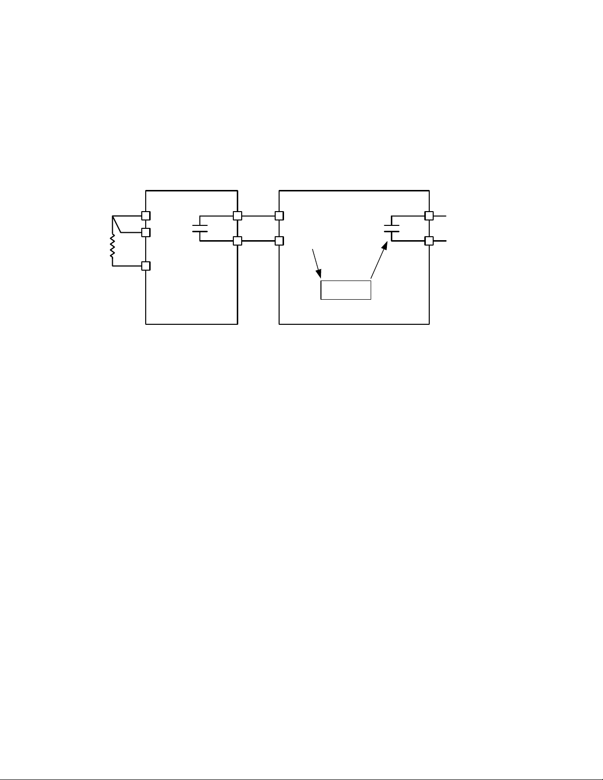
Temperature Controller Monitoring
Any Temperature Controller equipped with a contact output may be connected to the M-3425A and controlled
by the relay's programmable IPSlogic function. Figure 1 is an example of a typical Temperature Controller
Monitoring application. The Omron E5C2 Temperature Controller is a DIN rail mounted RTD interface to the
M-3425A Generator Protection relay. The E5C2 accepts type J or K thermocouples, platinum RTDs or
thermistors as its input. Supply voltage for the E5C2 accepts 110/120 V ac, 50/60 Hz, or 220/240 V ac 50/60
Hz or 24 V dc.
Temperature
Controller
Omron E5C2
P.D. 750
or equivalent
IN X
IN RTN
M-3425A
IPSlogic
Alarm/Trip
R1
C
R2
Figure 1 Typical Temperature Controller Monitoring Application
I/O Expansion (optional)
Optional I/O Expansion provides an additional 15 form 'a' output contacts and an additional 8 control/status
inputs. Output LEDs indicate the status of the output relays.
Tests and Standards
The relay complies with the following type tests and standards:
Voltage Withstand
Dielectric Withstand
IEC 60255-5 3,500 V dc for 1 minute applied to each independent circuit to earth
3,500 V dc for 1 minute applied between each independent circuit
1,500 V dc for 1 minute applied to IRIG-B circuit to earth
1,500 V dc for 1 minute applied between IRIG-B to each independent circuit
1,500 V dc for 1 minute applied between RS-485 to each independent circuit
Impulse Voltage
IEC 60255-5 5,000 V pk, +/- polarity applied to each independent circuit to earth
5,000 V pk, +/- polarity applied between each independent circuit
1.2 by 50 μs, 500 ohms impedance, three surges at 1 every 5 seconds
Insulation Resistance
IEC 60255-5 > 100 Megaohms

–16–
M-3425A Generator Protection Relay
Electrical Environment
Electrostatic Discharge Test
EN 60255-22-2 Class 4 (8 kV)—point contact discharge
EN 60255-22-2 Class 4 (15kV)–air discharge
Fast Transient Disturbance Test
EN 60255-22-4 Class A (4 kV, 2.5 kHz)
Surge Withstand Capability
ANSI/IEEE 2,500 V pk-pk oscillatory applied to each independent circuit to earth
C37.90.1- 2,500 V pk-pk oscillatory applied between each independent circuit
1989 5,000 V pk Fast Transient applied to each independent circuit to earth
5,000 V pk Fast Transient applied between each independent circuit
ANSI/IEEE 2,500 V pk-pk oscillatory applied to each independent circuit to earth
C37.90.1- 2,500 V pk-pk oscillatory applied between each independent circuit
2002 4,000 V pk Fast Transient burst applied to each independent circuit to earth
4,000 V pk Fast Transient burst applied between each independent circuit
■NOTE: The signal is applied to the digital data circuits (RS-232, RS-485, IRIG-B, Ethernet communication
port and field ground coupling port) through capacitive coupling clamp.
Radiated Susceptibility
ANSI/IEEE 25-1000 Mhz @ 35 V/m
C37.90.2
Output Contacts
ANSI/IEEE Make 30 A for 0.2 seconds, off for 15 seconds for 2,000 operations, per Section 6.7.1,
Tripping
C37.90.0 Output Performance Requirements
Atmospheric Environment
Temperature
IEC 60068-2-1 Cold, –20° C
IEC 60068-2-2 Dry Heat, +70° C
IEC 60068-2-3 Damp Heat, +40° C @ 93% RH
Mechanical Environment
Vibration
IEC 60255-21-1Vibration response Class 1, 0.5 g
Vibration endurance Class 1, 1.0 g
IEC 60255-21-2Shock Response Class 1, 5.0 g
Shock Withstand Class 1, 15.0 g
Bump Endurance Class 1, 10.0 g

–17–
M-3425A Generator Protection Relay
Compliance
UL-Listed per 508 – Industrial Control Equipment
UL-Listed Component per 508A Table SA1.1 Industrial Control Panels
CSA-Certified per C22.2 No. 14-95 – Industrial Control Equipment
CE Safety Directive – EN61010-1:2001, CAT II, Pollution Degree 2
Physical
Without Optional Expanded I/O
Size: 19.00" wide x 5.21" high x 10.20" deep (48.3 cm x 13.2 cm x 25.9 cm)
Mounting: The unit is a standard 19", semiflush, three-unit high, rack-mount panel design, conforming to
ANSI/EIA RS-310C and DIN 41494 Part 5 specifications. Vertical or horizontal panel-mount options are
available.
Approximate Weight: 17 lbs (7.7 kg)
Approximate Shipping Weight: 25 lbs (11.3 kg)
With Optional Expanded I/O
Size: 19.00" wide x 6.96" high x 10.2" deep (48.3 cm x 17.7 cm x 25.9 cm)
Mounting: Theunitisastandard 19", semiflush, four-unit high, rack-mount panel design, conforming to ANSI/
EIA RS-310C and DIN 41494 Part 5 specifications. Vertical or horizontal panel-mount options are available.
Approximate Weight: 19 lbs (8.6 kg)
Approximate Shipping Weight: 26 lbs (11.8 kg)
Recommended Storage Parameters
Temperature:
5° C to 40° C
Humidity:
Maximum relative humidity 80% for temperatures up to 31° C, decreasing to 31° C
linearly to 50% relative humidity at 40° C.
Environment:
Storage area to be free of dust, corrosive gases, flammable materials, dew, perco-
lating water, rain and solar radiation.
See M-3425A Instruction Book, Appendix E, Layup and Storage for additional information.
Patent & Warranty
The M-3425A Generator Protection Relay is covered by U.S. Patents 5,592,393 and 5,224,011.
The M-3425A Generator Protection Relay is covered by a five year warranty from date of shipment.
Specification subject to change without notice.
External Connections
M-3425A external connection points are illustrated in Figures 2 and 3.

–18–
M-3425A Generator Protection Relay
Figure 2 External Connections (Without Optional Expanded I/O)
■■
■■
■NOTES:
1. See M-3425A Instruction Book Section 2.3, Setpoints and Time Settings, subsection for 64B/F Field Ground Protection.
2. Before making connections to the Trip Circuit Monitoring input, see M-3425A Instruction Book Section 5.5, Circuit Board Switches and
Jumpers, for the information regarding setting Trip Circuit Monitoring input voltage. Connecting a voltage other than the voltage that the unit is
configured to may result in mis-operation or permanent damage to the unit.
3. 88
88
8WARNING:ONLY DRY CONTACTS must be connected to inputs (terminals 5 through 10 with 11 common) because these contact
inputs are internally wetted. Application of external voltage on these inputs may result in damage to the units.
4. 88
88
8WARNING: The protective grounding terminal must be connected to an earthed ground any time external connections have been
made to the unit.
3AMP,250V(3AB)3AMP,250V(3AB)
RATED CURRENT
1A ,NOM 5 A ,NOM
0.01A NOM
64S
F4
IN
AUX COM 3
RS485
5
IN
6
IN
4
LAR O, FL 33773
6190 118th AVE NO.
BECKWITH ELECTRIC CO. INC.
727- 544- 2326
OUTPUTS
5 0 Hz 6 0 Hz SERIA L NO .
ALARMS
FOR CONTACT RATIN S SEE INSTRUCTION MANUAL
SELF- TEST
WARNIN ! CONTACT WITH TERMINALS MAY CAUSE ELECTRIC SHOCK
(52b)
INPUTS
3
IN
2
IN
1
IN
P/ S
RT N
IN
PS2
F2
PS1
COM2
ETHERNET
4
1
2
3
-
3
COUPLER
LDFI
E
12
-+
BA
V
ND
VA
C
VB
VB
456
+
79
8
C
VA
VCN
V
10 11 13
12
A
IB
I
35353535 36363636 39393939
37373737 38383838 40404040 41414141 4545
64
43434343
42424242 44444444
X
V
65
46 47 49
48 50
26
15
14 16 18
17 19
N
C
IIa
I
8
23
21
20 22 24 25
b
7
II
c
65
2PS
27 29
28 3130 32
S
4
P1
32
3433
1
53
51 52 54 55 57
56 58 60
59 61 62 63
IRI - B
RS 2 3 2
COM 2
F1
F3
64F
!
!
48
24
250
125
!
MODEL: M-3425A FIRMWARE: D-0150
-
++-
55268
65-18 6
685 2
1-85
5
RATED VOLTA E
60- 140VAC,50/60Hz
LISTED
83F4
IND.C ONT . EQ
R
LR 89464
NRT L/ C
R

–19–
M-3425A Generator Protection Relay
IN
RT N
IN IN IN IN INININ IN
87
9
10
11
12
14 13
INPUTS
RS 2 3 2
COM 2
ETHERNET
COM 2
727- 544- 2326
6190 118th AVE NO.
LAR O, FL 33773
BECKWITH ELECTRIC CO. INC.
WA RNIN ! CONT A CT W ITH T ERMINAL S MA Y CA USE ELECT RIC SHOCK
FOR CONTACT RATIN S SEE INSTRUCTION MANUAL
76 78
77 80
79 81 83
82 84 88
86
85 87 89 91
90 92 94
93 9695 97 9998
43
1
2
.QE.TNOC.DNI
DETSIL
CUS
83F4
R
P/ S
36363636
35353535 44444444
40404040
3838383837373737 39393939 42424242
41414141 43434343
64
VX
65
4545 46 47 48 49
COUPLER
D
E
IFL
IRI - B
23
AUX
N
D A
V
VAB
B
V
B
VC
C
V
A
VC
RS485
COM 3
+
--6
+IN
3
125
4
(52b)
VN
3
IN
INPUTS
4
5
IN IN
1
2
IN IN
A
I I B
RT N
IN
8
7
610
9
22 21
12
11
20 19
3AMP,250V(3AB)3AMP,250V(3AB)
58
54
52
50 51 53 56
55 57 62
60
59 61 63
F3 F4
32
PS2
10
C
IIN
SELF- TEST
ALARMS
a
IIb
87
OUTPUTS
15
13 14 17
16
18 17
20
19
18 22
21
16 15
c
ISP2
OUTPUTS
65
1SP
F1
3
42
2724
23 25 26
14 13
29
28 31
30
12 11
PS1
F2
1
34
33
9
68
66 67 69 70 71 72 74
73 75 101
100 102 104
103 105
!
48
!
125
250
24
!
0.01A NOM
64S
8
8
1
6
-
25 5
856
8
1
526
-
5
56
++ --
RATED VOLTA E
60- 140VAC,50/60Hz
MODEL: M-3425A FIRMWARE: D-0150
5 0 Hz 6 0 Hz S ERIA L NO.
1A , NO M RATED CURRENT 5A,NOM
64F
Figure 3 External Connections (With Optional Expaned I/O)
■■
■■
■NOTES:
1. See M-3425A Instruction Book Section 2.3, Setpoints and Time Settings, subsection for 64B/F Field Ground Protection.
2. Before making connections to the Trip Circuit Monitoring input, see M-3425A Instruction Book Section 5.5, Circuit Board Switches and
Jumpers, for the information regarding setting Trip Circuit Monitoring input voltage. Connecting a voltage other than the voltage that the unit is
configured to may result in mis-operation or permanent damage to the unit.
3. 88
88
8WARNING:ONLY DRY CONTACTS must be connected to inputs (terminals 5 through 10 with 11 common and terminals 68
through 75 with 66 and 67 common) because these contact inputs are internally wetted. Application of external voltage on these
inputs may result in damage to the units.
4. 88
88
8WARNING: The protective grounding terminal must be connected to an earthed ground any time external connections have been
made to the unit.
Other manuals for M-3425A
2
Table of contents
Other BECKWITH ELECTRIC Protection Device manuals


Popular Protection Device manuals by other brands


Guardian
Guardian Diablo Cable SRL instruction manual

Palmer Safety
Palmer Safety H11110005 instruction manual

MAVIG
MAVIG OT50001 Series Instructions for use

Tektronix
Tektronix 80A09 instructions

Mustang Survival
Mustang Survival MSD660vAF owner's manual

Walter
Walter WaluCover Initial installation instructions