Engler Vet II User manual

Rev.C 10 / 09 / 2014
Page 1 of 28

Table of Contents
READ BEFORE YOU START.............................................................................................................2
COMPANY PROFILE..........................................................................................................................4
INTRODUCTION.................................................................................................................................5
INSTALLATION INSTRUCTIONS.......................................................................................................6
ULTRASONIC SCALER HANDPIECE................................................................................................9
SCALER MAINTENANCE.................................................................................................................11
St aight handpiece maintenance cont...............................................................................................14
MICROMOTOR MAINTENANCE......................................................................................................15
SCALER TROUBLESHOOTING.......................................................................................................16
POLISHER TROUBLESHOOTING...................................................................................................17
PROPHY ANGLE CLEANING AND MAINTENANCE INSTRUCTIONS...........................................18
WATER FILTER CLEANING INSTRUCTIONS.................................................................................19
SADDLE VALVE ASSEMBLY ....................................................................................................20
Options fo connecting the saddle valve............................................................................................22
WATER TANK INSTRUCTIONS.......................................................................................................23
WATER TANK CARE & MAINTENANCE.........................................................................................24
CARE AND MAINTENANCE OF YOUR PORTABLE WATER TANK..............................................24
OPTIONAL VET II ACCESSORIES.................................................................................................25
TECHNICAL DATA............................................................................................................................27
DIMENSIONS....................................................................................................................................28
Page 2 of 28

READ BEFORE YOU START
The scale handpiece, ult asonic t ansduce (stack), and tip a e wate cooled devices and must always have adequate
wate flow to function p ope ly. The amount of wate delive ed to the handpiece must be egulated acco ding to the
powe level. If the powe level is inc eased, the amount of wate must also be inc eased. Not having enough wate flow
th ough the scaling handpiece may pe manently damage the handpiece, will cause the handpiece to get hot, deg ade
t ansduce life and void the wa anty. Fo mo e info mation, please tu n to the Scaler Operating Instructions page.
When active, ult asonic tips vib ate at ove a million cycles pe minute, if it touches soft tissue o skin it will cause bu ns
due the f iction of the vib ation. The tip is not no mally hot but the ult asonic vib ation will bu n you if you touch it, this is
due to the f iction between the skin and the vib ating tip. This is no mal fo all ult asonic scale s. Neve let the scaling
tip touch soft tissue o skin, Engle Enginee ing Co po ation is not esponsible fo any damage caused by imp ope use
of this device and / o its accesso ies.
When using a wate bottle, it must be kept pumped to at least 30 PSI. The p essu e elease valve will slightly move out
showing the yellow inte io when p essu e builds up. As wate is used the p essu e will dec ease and the bottle must
be pumped to keep adequate p essu e.
Neve twist o bend you ult asonic stack. Be ca eful not to twist o bend the stack when inse ting o emoving it f om
the handpiece. Pull the stack st aight out to emove it. Always make su e the stack is p ope ly aligned when inse ted
into the handpiece. The e is a white dot in the handpiece and a hole in the stack, they must be aligned du ing inse tion.
Bending the stack o inse ting it inco ectly into the handpiece may i epa ably damage the stack and deg ade it’s
ability to vib ate. Imp ope inse tion of the stack may also damage the handpiece as well as cause it to get hot.
Damage caused by bending o fo cing the stack into the handpiece is not cove ed by the wa anty. A stack emoval
tool is available f om Engle Enginee ing Co po ation, it is pa t numbe 47903.
Do not alte the scaling tip. The tip is shaped to delive the optimum vib ating powe level and keep its optimum
f equency. Defo ming the tip in any way will cause the handpiece to get hot, deg ade vib ation powe and void the
wa anty.
D opping the handpiece with the stack and tip may alte o damage you tip and stack causing the handpiece to get
hot, deg ade powe / vib ation and void you wa anty.
Remove the tip and nosecone f om the stack and clean / disinfect afte eve y use. Stacks, tips, p ophy angles, ubbe
cups, st aight handpieces, bu s, and wate filte s, a e no mal wea and tea items. In o de to achieve optimum
pe fo mance they should be eplaced egula ly.
The ult asonic stack no mally last six months to a yea . To maintain optimum pe fo mance, eplace eve y six months to
a yea o as needed. Do not leave the ult asonic stack inside the ult asonic handpiece fo long pe iods of time. The
O- ings may d y out and make it difficult to emove the stack.
Lub icate the stack O- ings with an app op iate lub icant fo you p actice, fo example mine al oil o pet oleum jelly is
app op iate fo most p actices. A stack emoval tool and a maintenance kit a e available f om Engle Enginee ing
Co po ation.
The wate egulato has multiple tu ns. Tu n the wate egulato knob counte clockwise to open and clockwise to close.
The amount of tu ns equi ed is dependent on the supplied wate p essu e.
The powe switch is on the left side of the unit.
Tu n off the unit and disconnect the wate line when not in use.
Page 3 of 28

COMPA Y PROFILE
Engle Enginee ing Co po ation has been in business since 1964 and occupies an 8000 squa e foot
facility in Hialeah, Flo ida (USA). We manufactu e ult asonic dental scale s, polishe s and
combination units including elect o su ge y equipment and ult asonic inst uments fo the vete ina y
ma ket as well as a mic op ocesso cont olled anesthesia delive y system and a espi ato y monito .
Engle Enginee ing Co p. acqui ed the exclusive manufactu ing and ma keting ights of Dynax
p oducts, including st etche s, animal est aint devices, comfo t cots, heating pads, and othe
p oducts. We also acqui ed the Alpha-Sonic, O a-Sonic, and P o-Sonic line of piezo scale s.
Engle Enginee ing Co po ation’s b and name vete ina y p oducts p oudly include:
Excelsior, high speed dental ai unit with vacuum / elect o-su ge / ult asonic scale / low speed / high
speed / ai / wate sy inge,
Son - Mate II, ult asonic scale / polishe ,
Vet II - 25K ult asonic dental scale / polishe
Sonus II, ult asonic dental scale ,
Poli - X, mic omoto va iable speed polishe ,
Drill – Aire, high speed dental ai unit, high speed, ai / wate sy inge,
Drill – Aire Plus, high speed dental ai unit, high speed, low speed, ai / wate sy inge,
Scale - Aire Mini, high speed dental ai unit with ult asonic scale / high speed / low speed / ai /
wate sy inge,
Scale - Aire, high speed dental ai unit with ult asonic scale / high speed / low speed / ai / wate
sy inge and comp esso ,
Tri - Mate, ult asonic scale / mic omoto polishe / elect o-su ge,
A.D.S. 2000, mic op ocesso cont olled anesthesia delive y system / ventilato ,
Sentinel V.R.M., espi ato y monito .
We manufactu e all of the inse ts and tips used in the Engle p oducts as well as many othe s on the
ma ket today in the 18K and 25K f equency ange.
Ou epai depa tment has the technical knowledge to epai and maintain most dental devices
manufactu ed by othe companies including Sho line.
Engler Engineering Corporation’s foreign sales are handled through a large and growing network
of veterinary distributors. At the present time we are represented throughout Europe, South and
Central America, Canada, Asia, ew Zealand, Australia, the Middle East, and most other countries.
If you have any questions or comments, please contact:
Engler Engineering Corporation
1099 East 47th Street, Hialeah, Florida 33013
800-445-8581 – 305-688-8581 – FAX 305-685-7671
Web site: www.englerusa.com Help site: www.engler411.com
4

I TRODUCTIO
Thank you fo pu chasing the Engle Vet II Ult asonic Scale .
The design of the Vet II scale ci cuit y uses integ ated compute technology along with ou Time Remote
Feedback Ci cuit y. This combination p oduces a powe ful and potent tool against pe iodontal disease. A
einfo ced solid aluminum chassis su ounds the ci cuit boa d, p oviding a ve y du able and eliable unit.
The dental scale utilizes an ult asonic p inciple of ope ation. The ci cuit y conve ts o dina y line voltage to an
ope ating f equency of app oximately 25,000 Hz. This f equency is then amplified and delive ed to the scaling
tip. As a esult, the tip vib ates at this ult asonic f equency with an amplitude of 0.001 to 0.004 in. (25.4 um to
102 um).
In designing ou unique Engle tips, wate flows inte nally th ough the tip as it vib ates. As the bubbles in the
lavage a e bacte icidal, the ene gy eleased collapses and dest oys the bacte ial cell walls. The wate flowing
inte nally th ough the tip, effectively cools the a ea and assists in emoving any deb is f om the ope ative site.
This device is equipped with a digital eadout that p ovides an indication of the powe that the unit is set at.
PLEASE READ VERY CAREFULLY
Engle Enginee ing Co po ation makes eve y effo t to ve ify that all pa ts fo the device along with any optional
accesso ies o de ed we e shipped f om ou facility in Hialeah, Flo ida and a e included in this shipment. It is
impe ative that the shipment be inspected immediately upon a ival. Should any pa ts be missing o damaged,
Engle Enginee ing must be notified immediately. All claims submitted afte fifteen days of eceipt will not be
valid.
All devices manufactu ed and/o sold by Engle Enginee ing Co po ation a e built and tested to app oved
standa ds. Any modification to the device, cables o hoses, initiated by othe s nullifies all wa anty statements.
Engle Enginee ing Co po ation will not be held liable fo any loss, damage, inju y o death due to non-
autho ized se vice and / o imp ope installation and / o imp ope use of the device.
This manual is not intended to teach dentist y. The info mation contained he ein is intended only as a guide.
Individuals not p ope ly t ained in dentist y should not use this equipment. It is intended fo p ofessional use
only.
5

I STALLATIO I STRUCTIO S
Befo e installing o ope ating you new VET II, ca efully ead and follow all of the inst uctions.
IMPORTA T: This device must be connected to a clean, filte ed, wate supply, capable of delive ing 30 to 60
psi (2.0 to 4.2 kg/cm2) of wate input p essu e. This unit comes with an In-Line wate filte (P/N: A52030).
When kept clean and f ee of fo eign matte , it will assist in p ope wate flow to the unit. If the wate p essu e in
you office is above 60 psi, we ecommend you install a wate p essu e egulato on the supply line to you
scale .
CONNECTING WATER SUPPLY:
We st ongly ecommend that a manual shut off valve
be placed p io to the Female Quick Disconnect, so
that the wate can be completely shut-off, and line
p essu e elieved, when the unit is not in use.
This device comes equipped with an 8 foot (244 cm)
wate line, a male quick disconnect fitting, a wate
filte and a coupling body.
To connect to a wate supply, we suggest using one
of the fou options shown on the next two pages.
44301 Male quick disconnect
** Please note, male quick disconnect is supplied as a
standa d item with all Engle scale s.
PLEASE REMEMBER -
It is recommended that you disconnect the device from the water supply when it
is not in operation. Failure to disconnect the device from the water supply when
it is not in operation will void your warranty.
Engler Engineering Corporation will assume no liability for damages due to not
following recommendations in the Engler manuals.
6

Connecting wate supply, cont.
1. Female Quick Disconnect (P/N: 44300) - This is the
female mating connecto to the male quick disconnect
supplied with the VET II . Use this to c eate a custom
wate installation utilizing ¼ “ I.D. wate tubing.
44300 Female quick disconnect
2. Saddle Valve Assembly (P/N: A44303) - This kit contains
all pa ts to quickly and easily connect you unit to an
existing existing 3/8" to 1-3/8" coppe tubing cold wate
supply line.
A44303 Saddle valve assembly with female
quick disconnect & tubing
3. Faucet Adapte Assembly (P/N: A22303) - This sc ews
onto an existing faucet and has a female quick
disconnect included.
A22303 Faucet attachment
with female quick disconnect & tubing
4. Po table Wate Tank (P/N: PT-1) - This is a self-contained
wate sou ce, which is ideally suited fo po table
ope ation. We suggest using distilled wate and fill the
tank to the wate fill line (app oximately 2/3). Tighten the
cap, inse t the male quick disconnect on the wate line
into the female quick disconnect on top of the tank,
p essu ize the tank by pumping the handle until the
p essu e elief valve’s yellow indicato begins to show.
Lock the handle in place.
IMPORTA T: Engler strongly recommends the services of a professional plumber. Engler Engineering
Corporation will not be held liable for any damage including, but not limited to leakage caused by
improper installation of our products.
7

Connecting water supply, cont.
PLEASE NOTE: Mine als and fo eign pa ticles in the wate may cause a buildup o blockage of hoses and
pa ts. The wate filte supplied with this device must be opened and inspected qua te ly and we suggest that
the filte disc and O- ing be cleaned egula ly and changed out at least once a yea . See WATER FILTER
CLEANING INSTRUCTIONS.
CO ECTI G POWER SUPPLY:
Plug the male end of the powe co d into a g ounded powe outlet. DO NOT emove o bypass the g ound pin
f om the powe co d of this device. Doing so will void the wa anty.
8
ULTRASO IC SCALER HA DPIECE
Note: Wate lines we e pu ged p io to shipping. When activating the Vet II fo the fi st time, please
follow these inst uctions.
To begin:
WITH O STACK / I SERT I THE HA DPIECE, otate the powe cont ol knob to the ight, the
knob will click “on” and the g een LED will illuminate. This indicates that the scale has powe and is
eady to be used. Adjust the POWER CO TROL knob to the MI IMUM powe setting, (counte -
clockwise otation), set the WATER CO TROL to its MAXIMUM setting by otating it
counte clockwise, (knob will otate up to 3 and a half tu ns fo maximum wate flow).
Hold the handpiece ove a cuspido o sink and dep ess the footswitch until wate comes out of the
handpiece, this should only take a few seconds.. This step is done to insu e p ope ope ation of the
delayed cavitation featu e by emoving ai that may be t apped in the wate lines.
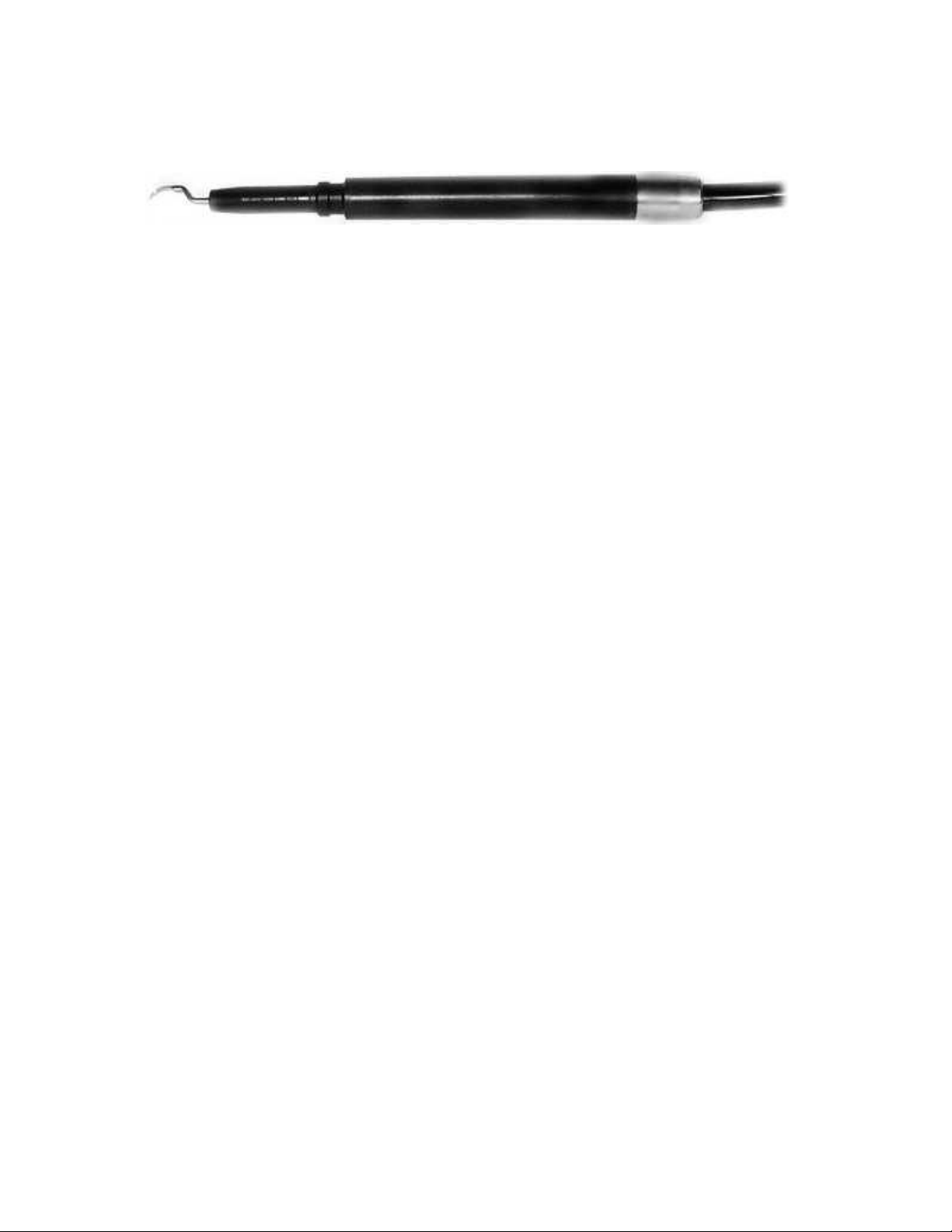
Place insert into handpiece:
To place an inse t into the handpiece, the e is no alignment necessa y; the ope ato need only d op
the inse t st aight into the handpiece. When the plastic f om the inse t meets the im of the
handpiece, push the two togethe to c eate a good seal. To change inse ts, the ope ato need only
pull the inse t st aight out of the handpiece and exchange it fo a diffe ent one. Pe iodically lub icate
O- ing on the inse t with pet oleum jelly o equivalent.
Set the powe cont ol and the wate cont ol to a level whe e you develop a fine mist at the tip.
OTE: Inserts sent from our facility are not sterilized.
WAR I G: The ultrasonic scaler is not designed to run without water. Running the handpiece
without water for 30 seconds or longer will damage the handpiece and void the warranty.
The 25K scale inse t is a one-piece design. This means the tip is not emovable f om the inse t.
The e is no nosecone to eplace.
Inserts sent from our facility are not sterilized.

BASIC SCALI G PROCEDURES
1. Befo e placing tip into patient’s mouth, activate the scale handpiece ove a sink by dep essing the
footswitch. A fine mist, with the tempe atu e between cool to lukewa m to the touch is
ecommended. This should be accomplished with minimal powe and p ope wate flow.
2. It is ecommended that when a tip is placed into a patient’s mouth, the lips, cheek and tongue
be et acted to p event contact.
3. Place the tip into the patient’s mouth and dep ess the footswitch to activate the scale .
4. B ing the tip to the tooth and gently move it ove the su face of the tooth with an e asing motion.
5. A saliva ejecto o HVE is ecommended.
IMPORTA T: Do not leave the vibrating tip in one place as it can cause serious damage to the tooth or
surrounding tissues. Engler Engineering Corporation will not be liable for damage due to improper
use of this device.
ote: We have designed the this device with a featu e called Delayed Cavitation. This function pu ges the tip
of wate afte eleasing the footswitch to p event bacte ia f om ente ing the tip.
IMPORTA T: Excessive p essu e on the tip is not necessa y to emove calculus o ta ta . Enamel on the teeth
may be damaged o emoved if excessive p essu e is used. The enamel may be damaged if the scaling tip is
left to est in one spot fo even a few seconds. Using the tip, as a p y to emove calculus o ta ta is st ongly
discou aged as it can damage the teeth and incidentally change the shape of the tip, alte ing it's pe fo mance.
The no mal powe setting fo most p ocedu es should be nea mid- ange. Since eve y ope ato has a diffe ent
technique, the powe may be adjusted to satisfy specific equi ements. Ult asonic scaling p ocedu es a e not
intended fo soft tissue.
CAUTIO : Contact with Soft Tissue Will Cause Burns. Engler Engineering Corporation will not be liable
for damage or injury due to improper use of this device.
DE TAL PROCEDURES SHOULD BE PERFORMED O LY BY QUALIFIED PERSO EL.
THIS EQUIPME T IS FOR PROFESSIO AL USE O LY.
As with any p ecision inst ument, inse ts should be handled ca efully. To avoid damage to the inse t,
please familia ize you self with the installation. Bent o damaged inse ts should be eplaced.
The use of a face mask is ecommended when ope ating the scale , to avoid inhalation of
contaminated ae osol (wate mist) gene ated du ing the scaling p ocedu e.
10

SCALER MAI TE A CE
FI AL PROCEDURES AT THE E D OF EACH DAY:
1. Tu n the unit off.
2. Remove the inse t, inse with unning wate , then ste ilize.
3. Disconnect the unit f om its wate sou ce o tu n off the wate supply.
4. Clean and disinfect all su faces.
Scaler tip maintenance:
Inse ts may be ste ilized by autoclave o chemiclave, always following the manufactu e ’s inst uctions and
ecommendations. Do not autoclave ove 270 deg ees F o mo e than twenty (20) minutes. Do not leave
inse ts in the handpiece indefinitely as wate and sediment may make it difficult to emove, causing possible
damage to the inse t and handpiece.
Transducer / insert:
ote: To achieve optimum pe fo mance of you equipment, we ecommend that the inse t be eplaced eve y 6
months o as needed.
Chassis:
The chassis of you unit should be cleaned at the end of eve y ope ating day with a chemical ste ilization
solution. This p ocedu e could be done by sp aying a fine mist of ste ilization solution on the unit, allowing it to
emain on the chassis fo the length of time ecommended by the manufactu e . The su face should be wiped
with a clean damp cloth o as suggested by the chemiclave manufactu e . D y completely.
IMPORTA T: In using any chemical ste ilization solution please follow the manufactu e ’s suggested
p ocedu es.
HA DPIECE, FOOTSWITCH A D POWER CABLES:
Afte each p ocedu e, o at least once a day, it is suggested that the handpiece and its cable be tho oughly
cleaned and ste ilized. The ecommended p ocedu e is as follows:
Do not allow ste ilize solutions to ente the handpieces.
If ste ilize solution does ente handpieces, shake out, then inse o flush tho oughly with clean wate .
11
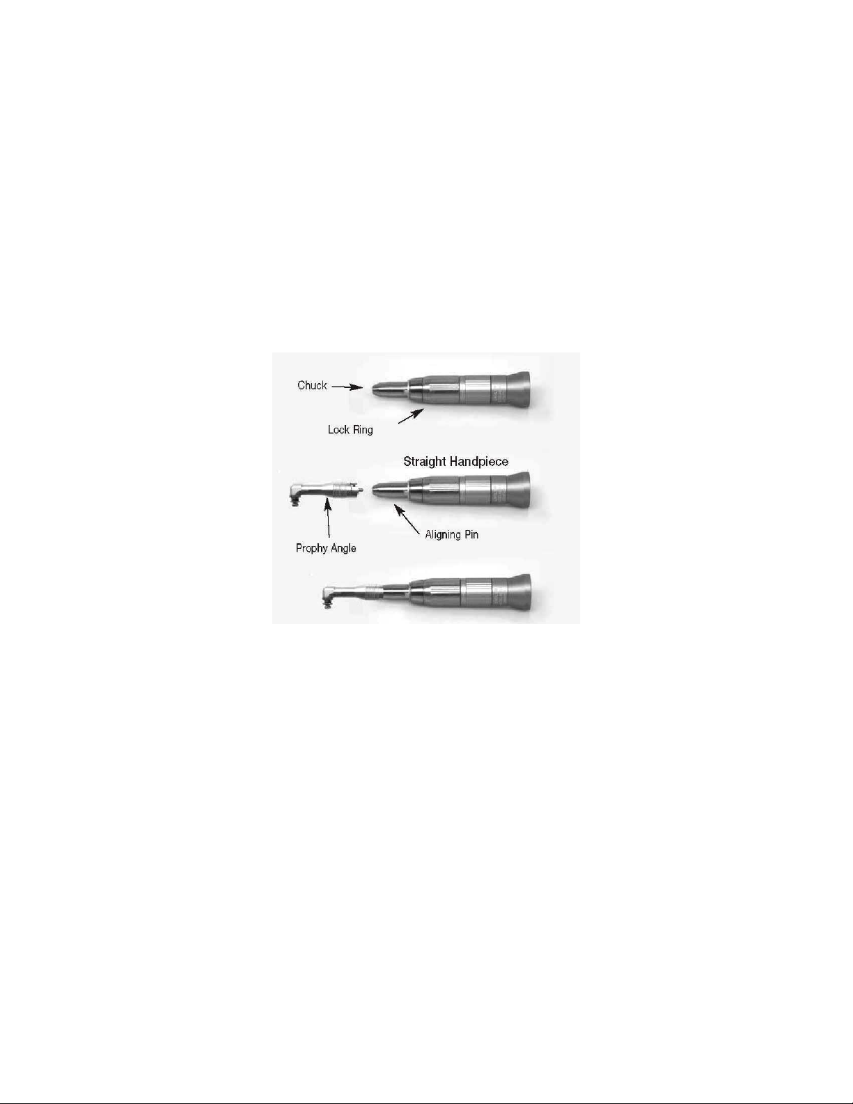
POLISHER I STALLATIO
1. Plug the mic omoto into the f ont of the cont ol box. This is done by inse ting the male connecto at the
end of the mic omoto cable, into the female eceptacle on the f ont panel of the unit and otating the lock
colla clockwise.
2. Slide the st aight handpiece down ove the top of the mic omoto .
3. Line up the notch of the p ophy angle with the aligning pin on the st aight handpiece, and then push the
shaft of the p ophy angle into the chuck of the st aight handpiece.
4. Rotate the lock ing clockwise, until it clicks and locks the p ophy angle in place.
5. Place a disposable ubbe -polishing cup on the end of the p ophy angle by snapping it on.
The p ophy angle is now secu ed and eady fo ope ation.
OTE 1: To use the polishe , otate the function selecto switch (fa left knob) clockwise to “polishe ”, the
g een LED indicato will illuminate. Select fo wa d o eve se.
OTE 2: High speed will damage the gea s in the p ophy angle, splatte the polishing compound and ove heat
the teeth. Always sta t at the lowest setting, then inc ease speed as necessa y.
SAFETY INFORMATION:
Neve tu n the lock ing while the handpiece is in ope ation.
1. Neve eve se the di ection of the mic omoto while it is in ope ation. Possible damage to the unit may
occu .
2. Do not lock o un the mic omoto / st aight handpiece assembly without a p ophy angle, cutting disc,
cont a-angle, o test shaft installed. doing so could damage the st aight handpiece and / o mic omoto .
3. Neve oil the mic omoto .
4. When installing the p ophy angle o othe accesso y, make su e that the lock ing is otated fully in the
unlock position, othe wise the accesso y can not be installed and the st aight handpiece will not ope ate.
5. Do not otate the selecto switch on the f ont of the cont ol box between fo wa d and eve se apidly.
always allow the mic omoto to stop between the two selections.
6. As this is a p ecision inst ument, always etu n it to Engle Enginee ing Co po ation fo maintenance and
epai .
12
POLISHER OPERATIO
1. Dampen the ubbe cup and place a small amount of polishing paste on it.
2. Rotate the POWER cont ol to the minimum setting in the PROPHY RANGE.
3. Dep ess the footswitch and the ubbe cup will begin to otate. The speed of otation may be adjusted to
you desi ed level by e-adjusting the POWER cont ol.
4. To keep the paste f om flying off the cup, maintain a low speed, b ing the cup up to the tooth befo e
dep essing the footswitch.
IMPORTA T: The p ophy angle is only ated to otational speeds up to 5000 RPM - the efo e, in o de to
p event p ematu e failu e of the angle keep the unit set in the p ophy ange.
5. High-speed settings will fling the polishing paste off of the ubbe cup. Always sta t with a low speed and
then adjust to a highe speed as equi ed.
6. Place the end of the angle into the patients’ mouth and gently apply the ubbe cup to the su face of the
tooth with a ci cula motion. Do not allow the ubbe cup to emain stationa y on one a ea fo an extended
pe iod of time.
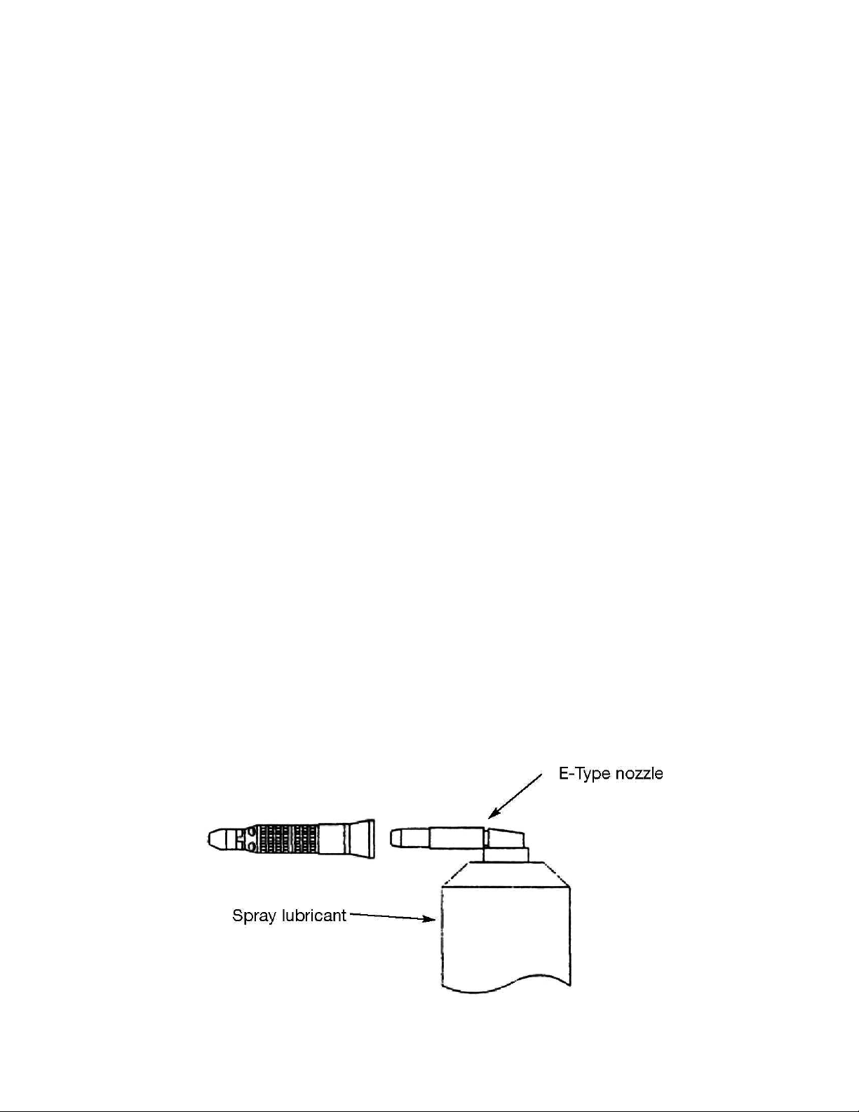
STRAIGHT HA DPIECE MAI TE A CE
LUBRICATIO :
The sp ay nozzle oiling method is optional but highly ecommended because it cleans as well as
lub icates. The alte nate method is to place 1 d op of app oved oil in the chuck hole. Do not lub icate the
handpiece while it is on the Mic omoto .
Lub ication of the st aight handpiece is equi ed at least once a week.
Lub ication by sp ay lub icant:
1. Make su e that the st aight handpiece is in the unlocked position p io to lub icating.
2. Install the E-Type nozzle by pushing it onto the top of the sp ay can. To lub icate, inse t the E-Type nozzle
into the bottom of the handpiece. Holding the two togethe tightly, with can in the up ight position, push
sp ay button fo seve al seconds, until oil begins seeping th ough the handpiece.
3. Oiling in this manne will fo ce di t and deb is f om the handpiece and lub icate at the same time.
NOTE: If sp ay time is too sho t, oil may not be p opelled into all a eas of the handpiece.
CLEA I G and STERILIZATIO OF HA DPIECE
13

St aight handpiece maintenance cont.
CLEA I G:
1. Wipe the handpiece clean with an alcohol-soaked soft tissue.
2. Neve clean the handpiece with boiling wate , chemical solutions, ult asonic cleane , o with wi e b ushes.
STERILIZATIO :
1. Autoclaving is ecommended fo the Engle st aight handpiece.
2. Clean the handpiece as desc ibed above.
3. Lub icate the handpiece as desc ibed above .
4. Place the handpiece in an autoclaving pouch and seal it in acco dance with the inst uctions on the pouch.
5. Autoclave the handpiece fo no longe than 20 minutes at 121 C (250 F), o 15 min. at 132 C (270 F).
Keep the st aight handpiece away f om wate vapo o mist that may settle and cause p ematu e
damage to the bea ings.
IMPORTA T: DO NOT UNDER ANY CIRCUMSTANCE, attempt to epai , disassemble o unsc ew the
st aight handpiece. Doing so may shift the inte nal sp ings, causing pe manent damage to the unit and will
void wa anty. If you expe ience p oblems du ing ope ation, call ou epai depa tment.
14

MICROMOTOR MAI TE A CE
The Mic omoto is capable of speeds up to 35,000 RPM fo use in cutting, sectioning and d illing. It contains
sealed bea ings and does not equi e any lub ication. The Mic omoto has cooling vents at the back of the
unit, Do not allow wate , oil, o any othe substance to ente these vents. Do not block the ai vents. Failu e to
keep deb is out of the mic omoto will sho ten the life of the unit and cause pe manent damage.
IMPORTANT:
1. NEVER change the di ection of the mic omoto while it is in ope ation. ALWAYS wait until it has come to a
full stop.
2. NEVER oil, o allow oil to get into the mic omoto .
15

SCALER TROUBLESHOOTI G
“O ” LED I DICATOR DOES OT LIGHT UP:
1. Ve ify that unit is switched ON.
2. The unit is not plugged in to a powe outlet: ve ify that the unit is plugged in.
3. Powe Outlet not active: t y anothe outlet.
4. Contact Engle Enginee ing Co po ation.
“O ” LED I DICATOR LIGHTS UP, O WATER FLOW:
1. Ve ify that the selecto switch is in scaling mode.
2. Ve ify wate line is connected and wate is flowing to unit.
3. Check that wate line is not kinked o twisted.
4. Check Wate Filte and disk: clean disk with plain wate and a toothb ush. If clogged, eplace O- ing
and disc.
5. If using Po table Wate Tank: Ve ify you have the co ect wate level and sufficient p essu e.
6. Wate blockage in tip: Leave inse t in handpiece, emove tip, dep ess footswitch. If wate does flow
out, tip is clogged, (Clean with # 3 (0.012”) piano wi e)
7. Contact Engle Enginee ing Co po ation.
“O ” LED I DICATOR LIGHTS UP, LITTLE OR O VIBRATIO / CAVITATIO O TIP:
1. Tip damaged: eplace tip.
2. Old o damaged inse t: eplace the inse t.
3. Contact Engle Enginee ing Co po ation.
HOT WATER COMI G OUT OF SCALI G HA DPIECE:
The inse t equi es a constant cool wate flow in o de to maintain wate tempe atu e below 100
deg ees F. You may co ect the p oblem by:
1. Adjusting wate flow knob highe (counte clockwise).
2. Tip clogged. See #6 above.
3. Check and / o eplace O- ing and disc in the inline filte .
4. Wate est iction in unit: contact Engle 's epai depa tment.
5. If using a Po table Wate Bottle, check wate level then pump to p essu ize the bottle.
I TERMITTE T OPERATIO :
1. Tip vib ates / cavitates and then stops:
2. Foot switch damaged: Contact Engle Enginee ing Co po ation.
3. Handpiece / cable damaged: Contact Engle Enginee ing Co po ation.
Tip action ceases ab uptly du ing ope ating p ocedu e.
1. T ansduce b oken: eplace.
2. Handpiece / cable damaged: Contact Engle Enginee ing Co po ation.
16

POLISHER TROUBLESHOOTI G
“ON” LED indicato does not light up:
1. Ve ify that unit is switched ON.
2. The unit is not plugged in to a powe outlet: ve ify that the unit is plugged in.
3. Powe Outlet not active: t y anothe outlet.
4. Contact Engle Enginee ing Co po ation.
“ON” LED indicato lights up polishe not functioning:
1. Switch unit to Polishe mode.
2. Mic omoto not plugged in: plug mic omoto in.
3. Sho t in Mic omoto o its co d: Contact Engle Enginee ing Co po ation fo inst uctions.
HOT STRAIGHT HANDPIECE:
1. St aight handpiece not lub icated p ope ly: Lub icate as shown on page 13.
2. Bea ings in st aight handpiece a e wo n, causing d ag. Contact Engle Enginee ing Co po ation.
HOT MICROMOTOR:
1. St aight handpiece causing d ag, lub icate st aight handpiece co ectly o eplace st aight handpiece.
Neve oil mic omoto .
2. Wo n b ushes in mic omoto , Contact Engle Enginee ing Co po ation.
3. Oil inside mic omoto , etu n to Engle Enginee ing Co po ation.
INTERMITTENT OPERATION:
Unit polishes and then stops:
1. Damaged mic omoto co d: contact Engle Enginee ing Co po ation.
2. Damaged footswitch: contact Engle Enginee ing Co po ation.
MISCELLANEOUS:
1. Mic omoto speed not adjustable ( uns at one speed): Retu n the complete VET II with mic omoto .
2. If the p ophy cup unsc ews, (“flies off”) the p ophy angle: Mic omoto is otating in the w ong di ection,
change di ection by otating the selecto on the f ont of the unit to the opposite di ection.
STRAIGHT HANDPIECE ROTATES ON THE MICROMOTOR:
1. St aight handpiece not p ope ly locked.
2. P ophy angle gea s wo n o Hai may be enmeshed in the gea s of the p ophy angle, clean p ophy
angle acco ding to p ophy angle cleaning and maintenance inst uctions (next page).
3. St aight handpiece o p ophy angle not p ope ly lub icated.
17
P-MM-E 35,000 RPM
Mic omoto W/Co d
P-SH-A1:1 St aight
handpiece
P-A1-B P ophy
Angle (Sealed
Bea ings)
Snap on ubbe cups
Polishing
paste

PROPHY A GLE CLEA I G A D MAI TE A CE I STRUCTIO S
The p ophy angle is a p ecision enginee ed dental device. all gea and shaft assemblies a e
made of high g ade stainless steel which must be kept f ee of deb is. If cleaned and lub icated
co ectly will p ovide long, t ouble-f ee se vice. The manufactu e ecommends eplacing p ophy
angles at least eve y 3 to 4 months depending on use. P ophy angles may va y. Use the following
inst uctions acco dingly.
DAILY CLEANING AND LUBRICATION:
1.) Remove p ophy angle f om low speed handpiece.
2.) Disca d used ubbe cup.
3.) Remove head cap by tu ning counterclockwise
to unsc ew the knu led nut with the w ench
p ovided.
4.) Wash the cap and head cavity tho oughly with a
toothb ush in a bowl of wa m soapy wate .
5.) Rinse tho oughly with unning wate and shake off
excess wate .
6.) DO NOT attempt to d y this pa t with pape o
cotton towels / swabs o gauze. Any pa ticles left
on the gea s will keep them f om tu ning p ope ly.
Use only alcohol to speed the d ying p ocess
and / o a blow d ye to tho oughly d y the angle.
7.) Lub icate by placing one d op of mine al oil on
the gea s of the head cap and a d op inside the
gea cavity.
8.) Being ca eful not to c oss-th ead, eassemble the
p ophy angle and wipe off all excess oil. Place a
new ubbe cup onto the head cap and confi m
that the gea s a e meshing p ope ly by otating
the cap – it should tu n easily. If not, emove and
t y again.
DO NOT use the w ench, only finge tighten.
9.) Slide the p ophy angle onto the handpiece and
lock the handpiece.
1.) Remove p ophy angle f om low speed handpiece.
2.) Disca d used ubbe cup.
3.) Use the w ench to emove the cap f om the head.
4.) Tu n clockwise to unsc ew the head (top po tion)
f om the body (bottom po tion).
5.) Place the cap, head and body into a bowl of hot
soapy wate .
6.) Wash tho oughly with a toothb ush.
7.) Rinse well with unning wate and shake off. DO
NOT attempt to d y these pa ts with pape o
cotton towels / swabs o gauze. Any pa ticles left
on the gea s will keep them f om tu ning p ope ly.
Use only alcohol to speed the d ying p ocess
and / o a blow d ie to tho oughly d y the angle.
8.) Lub icate by placing one d op of mine al oil on
each gea (see diag am).
9.) Being ca eful not to c oss-th ead, eassemble the
p ophy angle and wipe off all excess oil.
Place a new ubbe cup on the onto the cap and
confi m that the gea s a e meshing p ope ly by
otating the cap – it should tu n easily. If not,
emove the cap and t y again.
10.) Slide the p ophy angle onto the handpiece and
lock the handpiece.
Page 18 of 28
GEARS
(OIL HERE) WRENCH
HEAD CAP
BODY
HEAD
CAVITY
GEARS
CAP
WRENCH
CAP
KNURLED
NUT
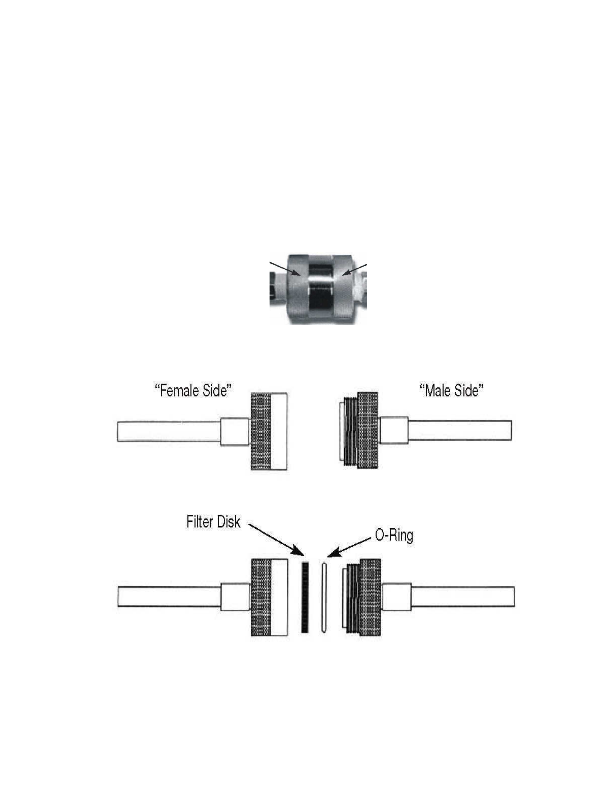
WATER FILTER CLEA I G I STRUCTIO S
SHOULD BE PERFORMED AT LEAST QUARTERLY
1. Tu n off wate supply to unit o disconnect the male f om the female wate connecto
2. Unsc ew filte by fi mly holding point “A” in you left hand and point “B” in you ight hand. (Refe to
Figu e) Next, unsc ew by simultaneously otating you left hand away f om you and otating you ight
hand towa d you. Continue this p ocess until the filte unsc ews into two sepa ate pa ts.
3. The filte body consists of two sides, one with an oute male th ead and anothe with an inne
female th ead.
4. Remove the O- ing.
5. Remove the filte disc by tu ning the female side ove and tapping it gently into the palm of you hand.
6. Replace with new filte disc and O- ing pa t # A52034.
7. Re-assemble the filte in eve se o de .
8. Tu n on the main wate supply and check fo leaks.
Point A Point B
Page 1 of 28

SADDLE VALVE ASSEMBLY
Installation Instructions
Installation inst uctions on the following two pages.
Page 20 of 28
Table of contents
Other Engler Dental Equipment manuals


