Engler Sonus II User manual


Table of Contents
READ BEFORE YOU START..............................................................................................................3
COMPANY PROFILE...........................................................................................................................4
INTRODUCTION..................................................................................................................................5
INSTALLATION INSTRUCTIONS.......................................................................................................7
SCALER OPERATING INSTRUCTIONS..........................................................................................10
SCALER MAINTENANCE..................................................................................................................12
WATER FILTER CLEANING INSTRUCTIONS.................................................................................1
SADDLE VALVE ASSEMBLY ...........................................................................................................17
WATER TANK INSTRUCTIONS.......................................................................................................20
WATER TANK CARE & MAINTENANCE..........................................................................................21
CARE AND MAINTENANCE OF YOUR PORTABLE WATER TANK...............................................21
TECHNICAL DATA............................................................................................................................22
DIMENSIONS.....................................................................................................................................22

RE D BEFORE YOU ST RT
The scaler handpiece, ultrasonic transducer (stack), and tip are water cooled devices and must always have adequate
water flow to function properly. The amount of water delivered to the handpiece must be regulated according to the
power level. If the power level is increased, the amount of water must also be increased. Not having enough water flow
through the scaling handpiece may permanently damage the handpiece, will cause the handpiece to get hot, degrade
transducer life and void the warranty. For more information, please turn to the Scaler Operating Instructions page.
When active, ultrasonic tips vibrate at over a million cycles per minute, if it touches soft tissue or skin it will cause burns
due the friction of the vibration. The tip is not normally hot but the ultrasonic vibration will burn you if you touch it, this is
due to the friction between the skin and the vibrating tip. This is normal for all ultrasonic scalers. Never let the scaling
tip touch soft tissue or skin, Engler Engineering Corporation is not responsible for any damage caused by improper use
of this device and / or its accessories.
When using a water bottle, it must be kept pumped to at least 30 PSI. The pressure release valve will slightly move out
showing the yellow interior when pressure builds up. As water is used the pressure will decrease and the bottle must be
pumped to keep adequate pressure.
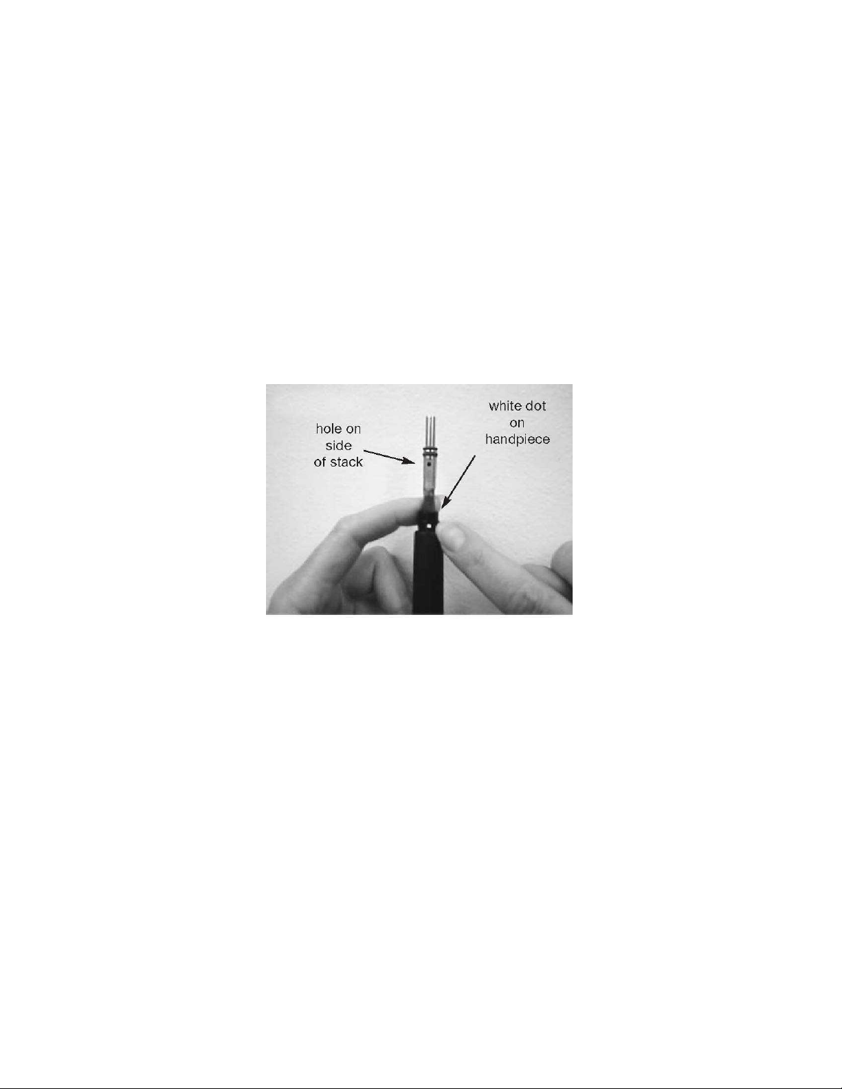
Never twist or bend your ultrasonic stack. Be careful not to twist or bend the stack when inserting or removing it from
the handpiece. Pull the stack straight out to remove it. Always make sure the stack is properly aligned when inserted
into the handpiece. There is a white dot in the handpiece and a hole in the stack, they must be aligned during insertion.
Bending the stack or inserting it incorrectly into the handpiece may irreparably damage the stack and degrade it’s ability
to vibrate. Improper insertion of the stack may also damage the handpiece as well as cause it to get hot. Damage
caused by bending or forcing the stack into the handpiece is not covered by the warranty. A stack removal tool is
available from Engler Engineering Corporation, it is part number 47903.
Do not alter the scaling tip. The tip is shaped to deliver the optimum vibrating power level and keep its optimum
frequency. Deforming the tip in any way will cause the handpiece to get hot, degrade vibration power and void the
warranty.
Dropping the handpiece with the stack and tip may alter or damage your tip and stack causing the handpiece to get hot,
degrade power / vibration and void your warranty.
Remove the tip and nosecone from the stack and clean / disinfect after every use. Stacks, tips, prophy angles, rubber
cups, straight handpieces, burrs, and water filters, are normal wear and tear items. In order to achieve optimum
performance they should be replaced regularly.
The ultrasonic stack normally last six months to a year. To maintain optimum performance, replace every six months to
a year or as needed. Do not leave the ultrasonic stack inside the ultrasonic handpiece for long periods of time. The
O-rings may dry out and make it difficult to remove the stack.
Lubricate the stack O-rings with an appropriate lubricant for your practice, for example mineral oil or petroleum jelly is
appropriate for most practices. A stack removal tool and a maintenance kit are available from Engler Engineering
Corporation.
The water regulator has multiple turns. Turn the water regulator knob counterclockwise to open and clockwise to close.
The amount of turns required is dependent on the supplied water pressure.
The power switch is on the left side of the unit.
Turn off the unit and disconnect the waterline when not in use.

COMP NY PROFILE
Engler Engineering Corporation has been in business since 19 4 and occupies an 8000 square foot
facility in Hialeah, Florida (USA). We manufacture ultrasonic dental scalers, polishers and
combination units including electro surgery equipment and ultrasonic instruments for the veterinary
market as well as a microprocessor controlled anesthesia delivery system and a respiratory monitor
for veterinary use only.
Engler Engineering Corp. acquired the exclusive manufacturing and marketing rights of Dynax
products, including stretchers, animal restraint devices, comfort cots, heating pads, and other
products. We also acquired the Alpha-Sonic, Ora-Sonic, and Pro-Sonic line of piezo scalers.
Engler Engineering Corporation’s brand name veterinary products proudly include:
Excelsior, high speed dental air unit with vacuum / electro-surge / ultrasonic scaler / low speed / high
speed / air / water syringe,
Son - Mate II, ultrasonic scaler / polisher,
Sonus II, ultrasonic dental scaler,
Poli - X, micromotor variable speed polisher,
Drill – ire, high speed dental air unit, high speed, air / water syringe,
Drill – ire Plus, high speed dental air unit, high speed, low speed, air / water syringe,
Scale - ire Mini, high speed dental air unit with ultrasonic scaler / high speed / low speed / air /
water syringe,
Scale - ire, high speed dental air unit with ultrasonic scaler / high speed / low speed / air / water
syringe and compressor,
Tri - Mate, ultrasonic scaler / micromotor polisher / electro-surge,
.D.S. 2000, microprocessor controlled anesthesia delivery system / ventilator,
Sentinel V.R.M., respiratory monitor.
We manufacture all of the inserts and tips used in the Engler products as well as many others on the
market today in the 18K and 25K frequency range.
Our repair department has the technical knowledge to repair and maintain most dental devices
manufactured by other companies including Shorline.
Engler Engineering Corporation’s foreign sales are handled through a large and growing
network of veterinary distributors. t the present time we are represented throughout Europe,
South and Central merica, Canada, sia, New Zealand, ustralia, the Middle East, and most
other countries.
If you have any questions or comments, please contact:
Engler Engineering Corporation
1099 East 47th Street, Hialeah, Florida 33013
800-445-8581 – 305-688-8581 – F X 305-685-7671
Web site: www.englerusa.com Help site: www.engler411.com
4

INTRODUCTION
Thank you for purchasing the Engler Sonus II Ultrasonic Scaler.
The design of the Sonus II scaler circuitry uses integrated computer technology along with our Time Remote
Feedback Circuitry. This combination produces a powerful and potent tool against periodontal disease. A
reinforced solid aluminum chassis surrounds the circuit board, providing a very durable and reliable unit.
The dental scaler utilizes an ultrasonic principle of operation. The circuitry converts ordinary line voltage to an
operating frequency of approximately 18,000 Hz. This frequency is then amplified and delivered to the scaling
tip. As a result, the tip vibrates at this ultrasonic frequency with an amplitude of 0.001 to 0.004 in. (25.4 um to
102 um).
In designing our unique Engler tips, water flows internally through the tip as it vibrates. As the bubbles in the
lavage are bactericidal, the energy released collapses and destroys the bacterial cell walls. The water flowing
internally through the tip, effectively cools the area and assists in removing any debris from the operative site.
This device is equipped with a digital readout that provides an indication of the power that the unit is set at.
PLEASE READ VERY CAREFULLY
Engler Engineering Corporation makes every effort to verify that all parts for the device along with any optional
accessories ordered were shipped from our facility in Hialeah, Florida and are included in this shipment. It is
imperative that the shipment be inspected immediately upon arrival. Should any parts be missing or damaged,
Engler Engineering must be notified immediately. All claims submitted after fifteen days of receipt will not be
valid.
All devices manufactured and/or sold by Engler Engineering Corporation are built and tested to approved
standards. Any modification to the device, cables or hoses, initiated by others nullifies all warranty statements.
Engler Engineering Corporation will not be held liable for any loss, damage, injury or death due to non-
authorized service and / or improper installation and / or improper use of the device.
This manual is not intended to teach dentistry. The information contained herein is intended only as a guide.
Individuals not properly trained in dentistry should not use this equipment. It is intended for professional use
only.
If you have any questions or comments, please contact:
Engler Engineering Corporation
1099 East 47th Street
Hialeah, Florida 33013
800-445-8581 – 305-688-8581 – F X 305-685-7671
Web site: www.englerusa.com Help site: www.engler411.com
5
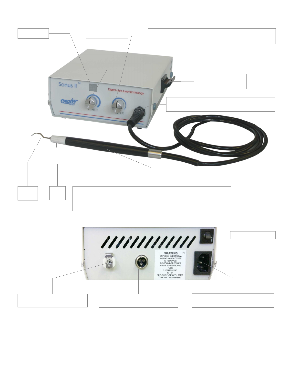
Handpiece holder
Multi turn water control, counterclockwise to
open, clockwise to close.
Power control
Scaler handpiece
(Ultrasonic stack inside) on first run, remove stack until
water flows then install stack.
Nose
cone
Scaling
tip
Scaler permanent connection (not a quick
disconnect, do not twist)
Display
Water quick disconnect
(connect water line here)
Power inlet (plug power cord
here, securely)
Resettable fuse
Foot switch quick disconnect
(connect foot switch here)
6
INST LL TION INSTRUCTIONS
Before installing or operating your new Sonus II, carefully read and follow all of the instructions.
IMPORT NT: This device must be connected to a clean, filtered, water supply, capable of delivering 30 to 0
PSI., 0 to 4.2 kg/cm2) of water input pressure. This unit comes with an In Line Water Filter
(part # A52030). When kept clean and free of foreign matter, it will assist in proper water flow to the unit. If the
water pressure in your office is above 0 psi, we recommend you install a water pressure regulator on the
supply line to your scaler.
CONNECTING W TER SUPPLY:
We strongly recommend that a manual shut off valve
be placed ahead of the Female Quick Disconnect, so
that the water can be completely shut-off, and line
pressure relieved, when the unit is not in use.
This device comes equipped with an 8 foot (244 cm)
water line, a Male Quick Disconnect fitting, a Water
Filter and a Coupling Body (which connects the water
line to the back of the unit).
The water line must be connected to the white fitting
located on the back of the unit before a connection is
made to the water source. To connect the water line.
Slide the white (male) insert into the coupling body (at
the back of the unit) until the metal latch locks it in
place making a clicking sound. The water line can
now be connected to your water source.
To connect to a water supply, we suggest using one
of the four options shown on the next two pages.
44301 Male Quick Disconnect
** Please note, Male Quick Disconnect is supplied as
a standard item with all Engler scalers.
IMPORT NT: Engler strongly recommends the services of a professional plumber.
Engler Engineering Corporation will not be held liable for any damage including, but
not limited to leakage caused by improper installation of our products.
7
Connecting water supply, cont.
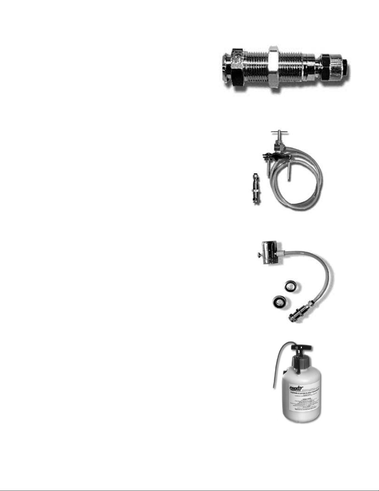
1. Female Quick Disconnect (part #44300) - This is the
female mating connector to the Male Quick Disconnect
supplied with the Sonus II . Use this to create a custom
water installation utilizing ¼ “ I.D. water tubing.
44300 Female quick disconnect
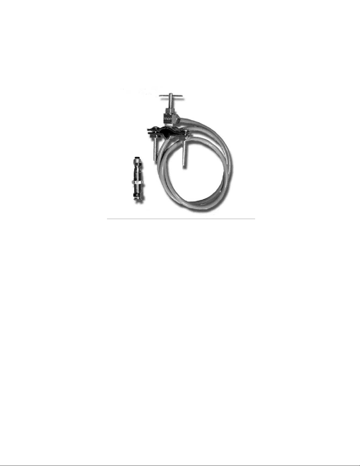
2. Saddle Valve Assembly (part # A44303) - This kit
contains all the parts necessary to quickly and easily
connect your unit to an existing existing 3/8" to 1-3/8"
copper, cold water supply line.
A44303 Saddle Valve Assembly with
Female Quick Disconnect & tubing
3. Faucet Adapter Assembly (part # A22303) - This screws
onto an existing faucet and includes a Female Quick
Disconnect.
A22303 Faucet attachment
with Female Quick Disconnect & tubing
4. Portable Water Tank (part # PT-1) - This self-contained
water source, is ideally suited for portable operation. We
suggest using distilled water and fill the tank to the water
fill line (approximately 2/3). Tighten the cap, insert the
Male Quick Disconnect on the water line into the Female
Quick Disconnect on top of the tank. Pressurize the tank
by pumping the handle until the pressure relief (on the
bottle) valve’s yellow indicator begins to show. Lock the
handle in place.
PT-1 Portable Water Tank
8

Connecting water supply cont.
The water filter included with this unit must be opened and inspected quarterly and we suggest that the filter
disc and O-ring be replaced at least once a year. See WATER FILTER CLEANING INSTRUCTIONS.
CONNECTING THE FOOT SWITCH:
To connect the footswitch to the unit, insert the male quick disconnect on the cable into the female quick
disconnect at the rear of the unit and tighten the securing nut by turning clockwise.
CONNECTING POWER SUPPLY:
First plug the power cord into the rear of the unit, then plug the other end of the into a grounded power outlet.
DO NOT remove or bypass the ground pin from the power cord. Doing so will void the warranty.
IMPORTANT: Your Sonus II has been equipped with a universal switching power supply and will not
require adjustments in this regard. See technical data for specifications.
9

SC LER OPER TING INSTRUCTIONS
Initial procedures at the start of every day:
1. Make sure the power switch is ON, it is located on the left side of the unit.
2. Adjust the power control knob to the minimum power setting fully counter-clockwise. The digital display
will read 1.
3. With no insert in the handpiece (no tip installed), set the water control to its maximum setting by
rotating it counterclockwise, (knob will rotate up to 3 and a half turns for maximum water) hold the
handpiece over a sink and depress the footswitch until water comes out in a stream. This should take
20 - 30 seconds. This step is done to insure proper operation of the delay cavitation feature by
removing air that may be trapped in the water lines.
Warning: DO NOT run the handpiece for more than 30 seconds without water
flow. Doing so will permanently damage the handpiece and void the warranty.
NOTE : The O-rings on the insert should be lubricated weekly with a thin film of petroleum jelly
to keep the O-rings on the insert from sticking in the handpiece.
4. Place the insert in the handpiece, push the white nosecone onto the handpiece and then install a sterile
tip into the nosecone. Rotate the nosecone clockwise to tighten the tip. Tighten firmly by hand.
IMPORT NT: It is important that you DO NOT over-tighten the tips, as this may damage the
handpiece, stack, and / or tip and void the warranty.
5. IMPORT NT: If you find that tightening the nosecone by hand is not successful, you may lightly
tighten the nosecone with the tip wrench. Since the tip wrench is designed to remove the tips, it is
important that you DO NOT over-tighten the tips with the tip wrench, as this may damage the stack, tip,
and / or the handpiece and void your warranty.
. Always keep the power control at the lowest setting and the water control to a level where you have a
fine mist at the tip. Higher power settings will result in hotter water.
NOTE: Tips sent from our facility are not sterilized.
IMPORT NT: Keep in mind that higher power levels tend to heat the out-flowing water. Temperature
control can be achieved by balancing the power with water flow volume. Thus, higher power settings
require high water flow rates and conversely lower power requires low water flow rates.
7. The scaler is now ready for use.
IMPORT NT: Operating this device with hot water may cause damage to gums, lips and tongue. If the
handpiece begins to get warm, stop and check water temperature. If it is hot, make sure that the power
is at the lowest setting and the water is set at a high enough setting to provide a lukewarm mist. Do not
use this device if the water temperature is too hot.
Engler Engineering Corporation will not be liable for damage due to improper use of this device.
10

ULTR SONIC SC LING PROCEDURES
1. Before placing tip into patient’s mouth, activate the scaler handpiece over a sink by depressing the
footswitch. A fine mist, with the temperature between cool to lukewarm to the touch is
recommended. This should be accomplished with minimal power and proper water flow.
2. It is recommended that when a tip is placed into a patient’s mouth, the lips, cheek and tongue
be retracted to prevent contact.
3. Place the tip into the patient’s mouth and depress the footswitch to activate the scaler.
4. Bring the tip to the tooth and gently move it over the surface of the tooth with an erasing motion.
5. A saliva ejector or HVE is recommended.
IMPORT NT: Do not leave the vibrating tip in one place as it can cause serious damage to the tooth or
surrounding tissues. Engler Engineering Corporation will not be liable for damage due to improper
use of this device.
Note: We have designed the this device with a feature called Delayed Cavitation. This function purges the tip
of water after releasing the footswitch to prevent bacteria from entering the tip.
IMPORT NT: Excessive pressure on the tip is not necessary to remove calculus or tartar. Enamel on the teeth
may be damaged or removed if excessive pressure is used. The enamel may be damaged if the scaling tip is
left to rest in one spot for even a few seconds. Using the tip, as a pry to remove calculus or tartar is strongly
discouraged as it can damage the teeth and incidentally change the shape of the tip, altering it's performance.
The normal power setting for most procedures should be near mid-range. Since every operator has a different
technique, the power may be adjusted to satisfy specific requirements. Ultrasonic scaling procedures are not
intended for soft tissue.
C UTION: Contact with Soft Tissue Will Cause Burns. Engler Engineering Corporation will not be liable
for damage or injury due to improper use of this device.
11

SC LER M INTEN NCE
FIN L PROCEDURES T THE END OF E CH D Y:
1. Turn the unit off.
2. Remove the tip and nose cone and sterilize.
3. Disconnect the unit from its water source or turn off the water supply.
4. Clean and disinfect all surfaces.
Ultrasonic Scaling Tips:
IMPORT NT: The scaling tips should be thoroughly cleaned and free of blood, tissue, or any other debris
before sterilization.
The scaling tips, nosecone and stack may be sterilized by autoclave or chemiclave, always following the
manufacturer’s instructions and recommendations. Do not autoclave over 270 degrees F or more than twenty
(20) minutes. It is recommended that you do not leave tips screwed into the handpiece indefinitely as water
and sediment may make it difficult to remove, causing possible damage to the insert and handpiece.
Transducer / insert:
The insert may be sterilized using the same methods as listed above. Do not sterilize the entire insert, tip
and nosecone assembly as one piece. Separate the tip from the insert before sterilization.
To re-install the insert into handpiece, follow procedures on the next page.
Note: To achieve optimum performance of your equipment, we recommend that the stack, tip and nosecone
be replaced every months or as needed.
Chassis:
The chassis of your unit should be cleaned at the end of every operating day with a chemical sterilization
solution. This procedure could be done by spraying a fine mist of sterilization solution on the unit, allowing it to
remain on the chassis for the length of time recommended by the manufacturer. The surface should be wiped
with a clean damp cloth or as suggested by the chemiclave manufacturer. Dry completely.
IMPORT NT: In using any chemical sterilization solution please follow the manufacturer’s suggested
procedures.
H NDPIECE, FOOTSWITCH ND POWER C BLES:
After each procedure, or at least once a day, it is suggested that the handpiece and its cable be thoroughly
cleaned and sterilized. The recommended procedure is as follows:
Note: If any chemicals are allowed to get into the handpiece, it must be flushed out with clean water.
1. Remove tip, and nosecone - sterilize these items as listed above.
2. Clean the outer surface of the handpiece and its cable with an antiseptic soap, rinse with water and
sterilize with a chemical sterilization solution.
3. Place sterile tip and nosecone into handpiece for next patient.
4. The footswitch and power cables should be cleaned periodically by spraying a fine mist of
sterilization / cleaning solution on the cables. It should remain on the cables for the length of time
recommended by the manufacturer. Wipe the surface with a damp cloth and dry the cables completely.
12
INSERT (TR NSDUCER) INST LL TION / REMOV L INSTRUCTIONS
You have purchased a precision instrument. Please handle gently - It is easily damaged
TO REMOVE THE ST CK:
1. Unscrew and remove the scaling tip by turning the plastic nosecone counterclockwise using the tip
wrench if necessary.
2. Pull off plastic nosecone. Pull stack straight up. DO NOT USE PLIERS! If you have difficulty pulling
the stack out, screw the tip back in (without the nosecone) and pull the stack straight out with the tip.
IF YOU STILL CANNOT REMOVE IT, PLEASE CALL US AT 800-445-8581.
DO NOT TWIST OR ROT TE ST CK WHILE IT IS IN THE H NDPIECE, S IT WILL D M GE THE
ST CK ND / OR H NDPIECE ND VOID YOUR W RR NTY.
TO INST LL THE ST CK:
Carefully remove the new stack from the clear shipping tube.
1. Locate the hole (see photo above) on the side of the stack. Align it with the white dot on the top of
the handpiece and let the stack slide down into the handpiece.
2. Gently push the stack down until it stops. There should be approximately ½ inch showing above the
handpiece.
DO NOT force the stack into the handpiece.
3. Push plastic nosecone onto scaler handpiece.
4. Place scaling tip into nosecone and turn nose-cone clockwise.
NOTE 1: Tighten nosecone / tip securely by hand. DO NOT USE TIP WRENCH.
NOTE 2: The O-rings on the stack should be lubricated every week with a small amount of petroleum jelly
(or equivalent) to keep the stack from sticking in the handpiece.
NOTE: Twisting the nosecone or tip with excessive force will damage the stack and void your warranty.
FOR FURTHER ASSISTANCE CALL CUSTOMER SERVICE 800-445-8581 OR 305- 88-8581
13
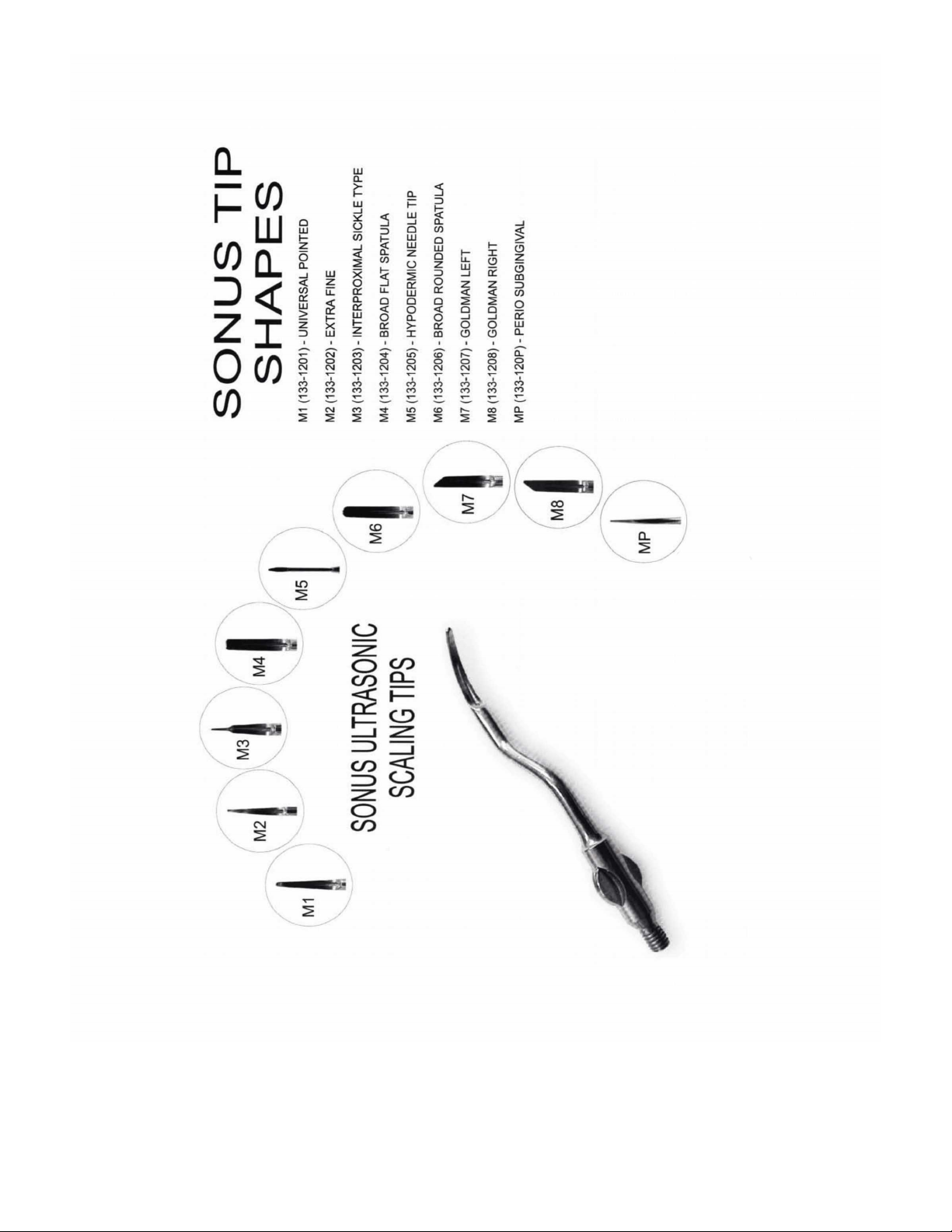
Some tips may no longer be available, please call Engler Engineering for more information
14

SC LER TROUBLESHOOTING
DISPL Y DOES NOT ILLUMIN TE:
1. Verify that unit is switched ON. The ON / OFF switch is located on the left hand side (facing the unit).
2. The unit is not plugged in to a power outlet. Verify that the unit is plugged in at both ends.
3. Power outlet not active: try another outlet.
4. Contact Engler Engineering Corporation.
DISPL Y ILLUMIN TES, NO W TER FLOW:
1. Verify water line is connected and water is flowing to unit.
2. Verify that the waterline is correctly connected to the coupling insert at the back of the unit.
3. Check if water line is kinked or twisted.
4. Check Water Filter and Filter Disk: clean disk with plain water and a toothbrush. If clogged, replace
O-ring and disc. Call Engler Engineering Corp. for replacement parts.
5. If using Portable Water Tank, verify you have the correct water level and sufficient pressure.
. Water blockage in tip: replace the tip. (Clean with # 3 (0.012”) piano wire)
7. Contact Engler Engineering Corporation.
DISPL Y ILLUMIN TES, LITTLE OR NO VIBR TION / C VIT TION T THE TIP:
1. Tip loose: tighten the tip.
2. Tip damaged: replace the tip.
3. Old or damaged stack: replace the stack.
4. Contact Engler Engineering Corporation.
HOT W TER COMING OUT OF SC LING H NDPIECE:
The Stack requires a constant flow of cool water flow in order to maintain water temperature below 100
degrees F. at the tip. You may correct the problem by:
1. Adjusting water flow knob higher (counter clockwise).
2. Tip clogged. Replace tip.
3. Check and / or replace O-ring and Filter Disc in the Inline Filter.
4. Water line may be twisted or kinked.
5. Water restriction in unit: contact Engler Engineering Corporation repair department.
. If using a Portable Water Bottle, check water level then pump to pressurize the bottle.
INTERMITTENT OPER TION:
Tip vibrates then stops:
1. Tip loose: tighten tip.
2. Foot switch damaged: Contact Engler Engineering Corporation.
3. Handpiece / cable damaged: Contact Engler Engineering Corporation.
Tip action ceases abruptly during operating procedure.
1. Tip not tightened: tighten tip.
2. Transducer broken: replace.
3. Handpiece / cable damaged, contact Engler Engineering Corporation.
15

W TER FILTER CLE NING INSTRUCTIONS
SHOULD BE PERFORMED AT LEAST QUARTERLY
1. Turn off water supply to unit or disconnect the male QD from the female QD.
2. Unscrew filter by firmly holding Point “A” in your left hand and Point “B” in your right hand. (Refer to Photo)
Next, unscrew by simultaneously rotating your left hand away from you and rotating your right hand toward
you. Continue this process until the filter unscrews into two separate halves.
3. The filter body consists of two sides, one with an outer male thread and another with an inner female
thread.
4. Remove the O-ring.
5. Next, remove the filter disc by turning the female side over and tapping it gently into the palm of your hand.
. Replace with new disc and O-ring, part # A52034.
7. Reassemble the filter in the reverse order as you disassembled it.
8. Turn on the water supply and check for leaks.
Point A Point B
16
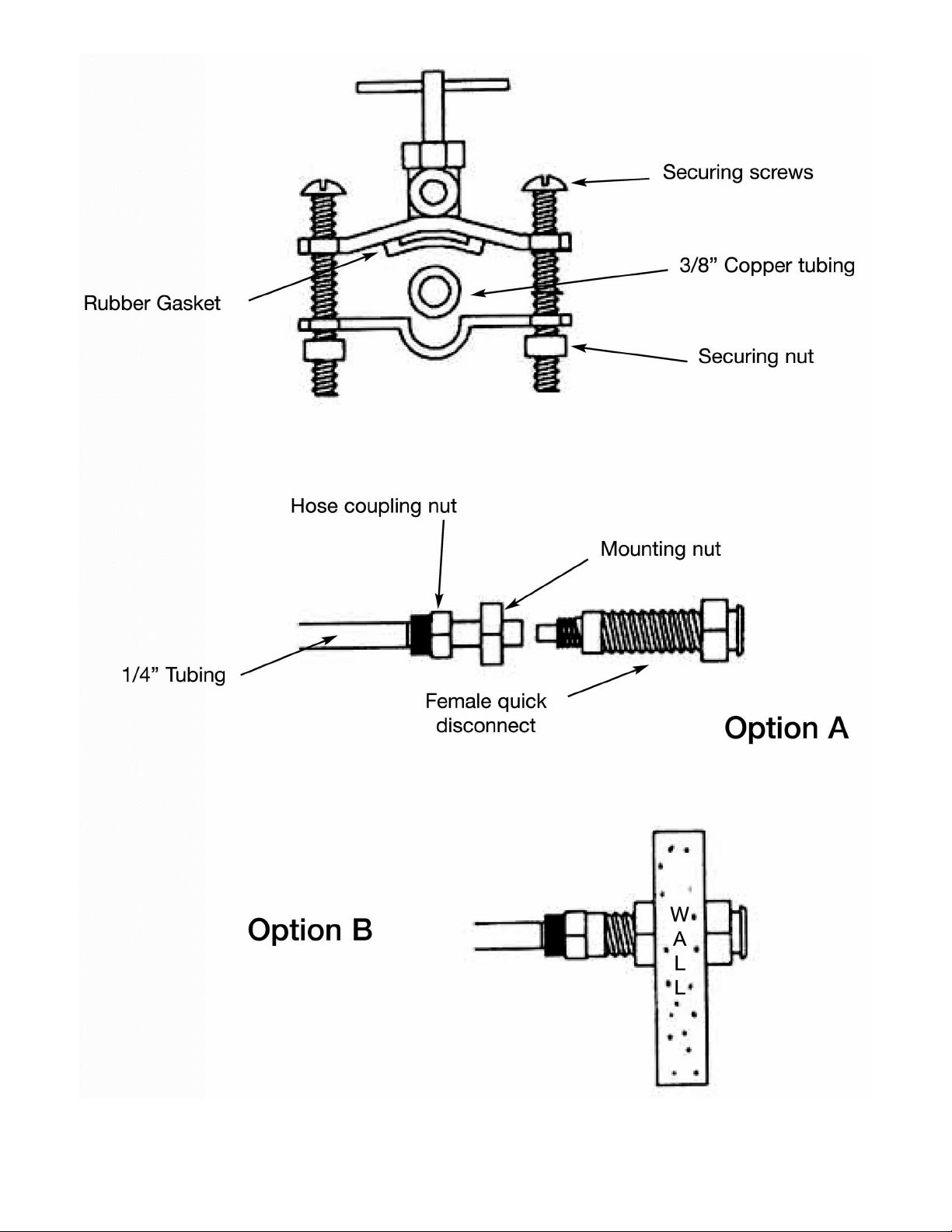
S DDLE V LVE SSEMBLY
Installation Instructions
To connect the saddle valve to an existing water source:
Be sure the tubing is copper and be sure to attach it to the cold water supply.
The copper tube should be between 3/8” and 1-3/8”.
Tighten the saddle valve's securing screws evenly.
DO NOT TTEMPT TO CONNECT THE S DDLE V LVE TO (plastic) PVC TUBING. THE PVC WILL
CR CK.
DO NOT OVERTIGHTEN, THIS MAY CAUSE THE COPPER TUBING TO CRIMP AND REDUCE FLOW.
17
18

To mount the female quick disconnect, there are two options.
Option “A” (Unmounted Assy.)
Take the free end of the ¼” water tubing that comes from the Saddle Valve and connect it to the Female Quick
Disconnect. This is done by placing the hose coupling nut over the water tubing and placing the hose into the
back of the Female Quick Disconnect, then tightening the coupling nut. Part # A44303 Saddle Valve Assembly
w / Female Quick Disconnect and tubing
Option “B” (Mounted Assy.)
If you wish, the Female Quick Disconnect may be mounted directly into a sink top or vanity counter. If you
choose this way, you must first drill a 1/2” diameter hole through the surface in the space desired. (see above)
Then install the Female Quick Disconnect and tighten the mounting nut to securely hold it in place. Then
proceed to place the hose coupling nut over the 1/4” water tubing. Place this tubing into the back of the Female
Quick Disconnect and tighten the hose coupling nut securely.
The copper tube is ready to be pierced.
Confirm that the Saddle Valve assembly is tightened snugly to the copper tube and the Female Quick
Disconnect is properly connected to the water line.
Turn the “T” handle of the saddle valve in a CLOCKWISE direction until it will go no further. Next, turn the “T”
handle in a COUNTERCLOCKWISE direction until resistance is felt. Water will now flow to your dental unit.
Check for leaks.
You may now connect the water line to the back of the dental unit.
NOTE: The “T” handle on the saddle valve does not shut water to the dental unit. It is only used to pierce
the copper tube. It is very important that you mount the saddle valve after a shut off valve.
ENGLER ENGINEERING CORPOR TION WILL NOT BE HELD LI BLE FOR NY D M GE INCLUDING,
BUT NOT LIMITED TO LE K GE C USED BY IMPROPER INST LL TION OF OUR PRODUCTS.
IT IS STRONGLY SUGGESTED TH T PROFESSION L PLUMBER M KE NY NECESS RY
INST LL TIONS OR CONNECTIONS.
19

W TER T NK INSTRUCTIONS
PT-1 Water Tank
DIRECTIONS:
1. Release Air Pressure by PULLING and TURNING pressure relief valve, (black knob) located on
the side of the bottle.
2. Remove pump and cap assembly.
3. Fill tank with distilled water or medicated solution up to the “FILL LINE” mark (approx. 2/3) . Do
NOT fill beyond this line.
4. Replace pump and cap assembly and tighten securely.
5. Pressurize tank by pumping it approximately 20 - 40 times (depending on the amount of liquid
used). If a hissing sound is detected, tank is over-pressurized. Stop pumping. Leave tank on a
level surface until hissing stops. Insert the Male QD from the waterline from scaler into Female QD
provided on tank.
20
Table of contents
Other Engler Dental Equipment manuals


Popular Dental Equipment manuals by other brands


Durr Dental
Durr Dental Hygoclave 40 Installation and operating instructions

VOP
VOP CeramicMaster E10 user manual

GEOSOFT DENT
GEOSOFT DENT ESTUS user manual

VHF
VHF E5 Original operating instructions

Ivoclar Vivadent
Ivoclar Vivadent Ivomat IP3 operating instructions

DENTAURUM
DENTAURUM Elegance Instructions for use