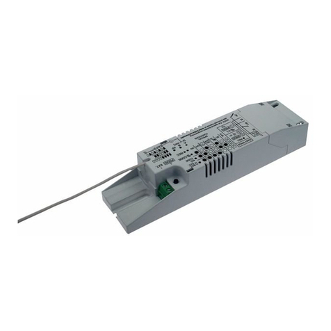
enika L8 R DALI ZHAGA User manual

E2020/12 (L8 R DALI ZHAGA) A4
L8 R DALI ZHAGA
CZ Přijímač s DALI výstupem
GB Receiver with DALI output
ENIKA.CZ s.r.o.
Vlkov 33, 509 01 Nová Paka, Czech Republic
Telefon: +420 493 773311, Fax: +420 493 773322
E-mail: [email protected], http://www.enika.cz
CZ
POPIS
Přijímač slouží k řízení jednotlivých bodů venkovního
osvětlení (VO). Řízení (komunikace) probíhá bezdrátově
pomocí protokolu LoRaWAN na frekvenci 868 MHz.
Výstupem přijímače jsou řídicí příkazy pro sběrnici DALI.
Přijímač L8 R DALI ZHAGA slouží zároveň i k napájení
sběrnice.
FUNKCE PŘIJÍMAČE
BEZDRÁTOVÁ SÍŤ
Každé svítidlo vybavené přijímačem bezdrátového ovlá-
dání VO musí být připojeno do bezdrátové sítě, kterou
spravuje řídicí systém sítě VO. Pro připojení do bezdráto-
vé sítě řídicího systému je nutné znát unikátní identifiká-
tory vytištěné na typovém štítku přístroje (QR kódy).
Jednotlivá svítidla nebo skupiny svítidel pak mohou být
řízena časovým plánem, který je nastaven v řídicím sys-
tému.
Přijímač umožňuje řízení výstupního výkonu v rozsahu 0-
100 %.
Přijímač na dotaz řídicího systému poskytuje informace o
maximální, minimální a aktuální teplotě, případně o době
překročení maximální teploty, počtu hodin provozu svě-
telného zdroje.
Přijímač po provedené adresaci je schopen detekovat
chybu světelného zdroje, chybu předřadníku a sběrnice.
Hlášení o chybách je periodicky vysíláno do řídicího sys-
tému.
Pokud přijímač bezdrátového ovládání VO není připojen
do bezdrátové sítě, nebo došlo k poruše řídicího systému,
pak po 10 minutách od připojení napájení začne svítidlo
svítit na přednastavenou úroveň (typicky 100 %) výstup-
ního výkonu. Při dalším připojení napájení naběhne na
poslední nastavenou úroveň bez desetiminutového inter-
valu.
FUNKCE MAGNETICKÉHO TLAČÍTKA
Krátkým přiložením magnetu k tlačítku přijímače PROG
(obr. 1) se střídavémění jas svítidla připojeného
k předřadníku z 0 na 100% a naopak. Dlouhým přilože-
ním magnetu k tlačítku přijímače (obr. 1) dochází k po-
stupnému nárůstu nebo k poklesu jasu.
Signalizace provozních stavů přijímače:
- Svítí LED OUT –normální provoz, je-li výstupní výkon
>0%
- Blikání LED RF – signalizuje bezdrátovou komunikaci
- Střídavé blikání LED OUT a LED RF –není provedeno
prvotní nastavení svítidla (adresace DALI předřadníků)
UVEDENÍ DO PROVOZU
Přijímač se zatlačí do patice tak, aby největší kontakt za-
padl do největšího otvoru (obr. 2) a pak se otočí ve směru
hodinových ručiček, aby kontakty zapadly na své místo.
MONTÁŽ DO KONEKTORU ZHAGA Socket
SCHÉMA ZAPOJENÍ
Upozornění:
Připojení (odpojení) přijímače k síti a ke spotřebiči mohou
provádět alespoň pracovníci znalí podle §5 vyhlášky
50/1978 Sb.
Z důvodu možného zmenšení dosahu není vhodné umís-
tění přijímače blízko zdrojů elektromagnetického rušení.
Silné elektromagnetické pole může zhoršit nebo i zne-
možnit správnou funkci přijímače! Dosah je závislý i na
materiálu, do kterého je přijímač zabudován. Vodivé ma-
teriály a vodivé předměty v blízkosti antény přijímače do-
sah snižují.
Elektrický obvod, na který je spotřebič s přijímačem připo-
jen, musí být jištěn prvkem (pojistkou, jističem)
s vypínacím proudem max. 16 A.
PRVOTNÍ NASTAVENÍ(ADRESACE DALI)
Nastavení je nutné pro správnou detekci poruch na svíti-
dle
- stisknout a držet tlačítko PROG na přijímači bezdráto-
vého ovládání VO
- připnout napájecí napětí
- tlačítko držet po dobu 3s, až se rozsvítí LED OUT +
LED RF
- Tlačítko pustit a znovu krátce stisknout. Připojená svíti-
dla na DALI sběrnici se střídavě rozsvítí a zhasnou (in-
dikace probíhajícího adresování).
- LED OUT a RF při úspěšné kalibraci 3× souhlasně za-
blikají, pokud adresace úspěšná není zablikají 3× ne-
souhlasně (nebyl detekován žádný připojený DALI
předřadník)
- Zahájení adresace DALI svítidel lze provést i vzdáleně
pomocí příslušného příkazu řídícího systému
ENIKA.CZ s.r.o. tímto prohlašuje, že tento P8 R DALI
ZHAGA je ve shodě se základními požadavky a dalšími
příslušnými ustanoveními směrnice 1999/5/ES.
EN
DESCRIPTION
The receiver is used to control individual public lighting
points. Control (communication) takes place wirelessly
using the LoRaWAN protocol using the 868 MHz fre-
quency.
The output of the receiver are control commands for the
DALI bus.
The L8 R DALI ZHAGA receiver also serves to supply the
bus.
RECEIVER FUNCTIONS
WIRELESS NETWORK
Each luminaire equipped with a VO wireless control re-
ceiver must be integrated into a wireless network man-
aged by the VO network control system. To connect to
the wireless network of the control system, it is necessary
to know the unique identifiers printed on the type plate of
the device (QR codes). Individual luminaires or groups of
luminaires can then be controlled by a schedule that is
set in the control system.
The receiver allows control of the output power in the
range 0-100%.
The receiver provides information through the control sys-
tem regarding the maximum, minimum and actual tem-
perature, the time when the maximum temperature was
exceeded, hours of operation of the light source and the
current wattage.
After addressing, the receiver is able to detect a light
source error, ballast and bus error.
An error message is periodically sent to the control sys-
tem.
If the VO wireless control receiver is not connected to the
wireless network, or the control system has failed, then
10 minutes after the power is connected, the luminaire
will light up to a pre-set level (typically 100%) of output
power. The next time the power is connected, it will run to
the last set level without a ten minutes interval.
MAGNETIC BUTTON FUNCTIONS
By briefly applying the magnet to the button of the PROG
receiver (Fig. 1), the brightness of the luminaire connect-
ed to the ballast alternately changes from 0 to 100% and
vice versa. By applying the magnet to the receiver button
for an extended time (Fig. 1), the brightness gradually in-
creases or decreases.
Indication of operating states of the receiver:
- LED OUT lit - normal operation if the output power is >
0%
- Flashing RF LED - signals wireless communication
- Alternating flashing of LED OUT and LED RF - no initial
setting of the luminaire (addressing of DALI ballasts)
has been performed.
COMMISSIONING
The receiver is pushed into the socket so that the largest
contact fits into the largest hole (Fig. 2) and then it is
turned clockwise so that the contact snaps into place.
Notice:
The connection (disconnection) of the receiver to the
network and to the appliance should be performed by
workers familiar with §5 of Decree 50/1978 Coll.
It is not suitable to place the receiver close to sources of
electromagnetic interference due to the potential reduc-
tion of the range. Strong electromagnetic fields can impair
or even prevent the receiver from functioning properly!
The range also depends on the material in which the re-
ceiver is built. Conductive materials and conductive ob-
jects near the receiver antenna reduce the range.
The electrical circuit to which the appliance with the re-
ceiver is connected must be protected by an element
(fuse, circuit breaker) with a breaking current of max. 16
A.
INITIAL SETTINGS (CALIBRATION)
These settings are necessary for the correct detection of
faults in the luminaire.
- press and hold the PROG button on the VO wireless
control receiver.
- connect the power supply
- hold the button for 3 seconds until the LED OUT + LED
RF lights up.
- release the button and briefly press it again. The con-
nected luminaires on the DALI bus switch on and off al-
ternately (indication of addressing in progress).
- LED OUT and LED RF will flash 3 times in succession
during a successful addressing. If addressing is not
successful, they will flash 3 times inconsistently (no
connected DALI ballast detected).
- addressing of luminaires can also be started remotely
using the appropriate command from the control sys-
tem.
ENIKA.CZ s.r.o. hereby declares that this P8 R DALI
ZHAGA is in compliance with the essential requirements
and other relevant provisions of Directive 1999/5 / EC.
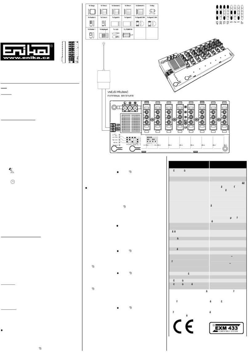
LED OUT
(červená/red)
LED RF
(zelená/green)
Tlačítko PROG
PROG button
Obr. 1, Fig. 1
Obr. 3, Fig. 3
Obr. 2, Fig. 2

Technická data /
Technical data
L8 R DALI ZHAGA
Počet kanálů /
Number of channels:
1
Maximální počet připoje-
ných zařízení / Maximum
number of connected de-
vices
8
Napájení / Power supply:
24 V ±10 % DC
Napájení sběrnice /
Bus bar power supply:
max. 20,5 V 20,5 mA
Výstupní řídicí signál /
Output control signal:
podle / according to
ČSN EN 62386-101, -102
(DALI)
Stupeň krytí / Protection:
IP 65 podle / according to
ČSN EN 60529
Provozní teplota /
Operating temperature:
-20 + 40 °C
Hmotnost / Weight:
76 g
Rozměry / Dimensions:
ø80 x 48 mm
Připojovací svorky /
Connecting terminals:
ZHAGA socket
Protokol / Protocol
LoRaWAN
Provozní kmitočet /
Frequency:
863 MHz –870 MHz
Dosah / Range:
5 km ve volném prostoru / in
open space
Na zařízení není dovoleno provádět dodatečné technické
úpravy!
It is forbidden to make any technical modifications to the
device!
Zařízení lze provozovat na základě aktuálního VO–R/10/.
(viz www.ctu.cz) a za podmínek v něm uvedených.
The device can be operated based on the current VO –
R/10/. (see www.ctu.cz) and under the conditions specified
therein.
Other enika Receiver manuals

enika
enika P8 R R Tango User manual
enika
enika Rx8 W3 User manual
enika
enika Rx8 E3 User manual
enika
enika L8 R 0110 NEMA User manual
enika
enika P8 R 2 N User manual
enika
enika Rx1 N D User manual
enika
enika Rx8 S3 User manual
enika
enika P8 R 8 S3 User manual
enika
enika RX1 N D User manual
enika
enika P8 R 2 DIN User manual
