ENMET Bullard AirGuard AGP User manual

AirGuardTM Operators Manual
Revision 2.08
31 January 2022

2
www.bullard.com
Table of Contents
Introduction ...............................................................................................................3
Safety Recommendations ...........................................................................................3
General Safe Use Considerations.................................................................................3
AirGuard Approvals ....................................................................................................4
AirGuard Specifications...............................................................................................5
Sensor Module Specifications......................................................................................6
Warranty ...................................................................................................................7
General Software Interface.........................................................................................8
Menu Function Interface Overview .............................................................................9
Battery Operation ....................................................................................................10
Compressor Pneumatic Connections..........................................................................11
Start-Up ...................................................................................................................14
Access Code..............................................................................................................17
Bump Test ................................................................................................................19
Sensor Menu ............................................................................................................20
Calibration ...............................................................................................................23
Settings Menu ..........................................................................................................29
Maintenance Menu ..................................................................................................31
Data Capture............................................................................................................32
Battery and Power Supply Operation ........................................................................35
Case Exterior ............................................................................................................36
ESD ..........................................................................................................................36
Air Filtration Filters...................................................................................................36
General Filter and Sample Train Parts .......................................................................37
AirGuard Parts..........................................................................................................38

AirGuardTM
3
www.bullard.com
Introduction
Thank you for selecting the Bullard AirGuard. The AirGuard is a portable breathing air system which meets NFPA
and OSHA requirements. It uses a three-stage filter system which removes contamination and odors in the
breathing air stream. The AirGuard reports both Carbon Monoxide and differential dew point values on a visible
and externally mounted liquid crystal display. It also has operator warning alarms for flow CFM (cubic foot per
minute) and calibration interval reminders. The AirGuard data log records all operational use and calibration
events for OSHA (Occupational Safety and Health Administration) compliance reporting.
Safety Recommendations
Important Reference Information
Note = Important information about use of the instrument.
Remarque = Informations importantes sur l'utilisation de l'instrument.
Caution = Affects Equipment –If not followed may cause damage to the instrument or
sensor.
Attention = affecte l'équipement - s'il n'est pas suivi, il peut endommager l'instrument
ou le capteur.
Warning = Affects personal safety –If not followed may cause bodily injury or death.
Avertissement = Affecte sécurité personnelle - non suivi peut causer des blessures
corporelles ou la mort.
General Safe Use Considerations
•AirGuard is an instrument designed for Grade D breathing air
compliance. It is important that the operator is trained by qualified
personnel to ensure proper use.
•The AirGuard is approved primarily for indoor locations and limited
outdoor use.
•Do not use the AirGuard unless you have been trained to operate the
instrument and fully understand its implementation as a health and
safety device. Inappropriate use can result in severe injury or death.
•Observe Proper Battery Maintenance and use only chargers supplied by
BULLARD to avoid battery damage and performance issues.
•Do not recharge AirGuard in a hazardous classified or environmental
location.
•Indoor recharging only.
PROOFING VIEW - SCALE: 2 : 1
LABEL, WARNING / INFO,
AIRGUARD
COMPUTER FILE NO.
04539-261_Label_Warning-Info_AirGuard.idw
DRAWING NO:
04539-261
SHEET: REV:
OF
2 2
B
UNLESS OTHERWISE S PECIFIED
DIMENSIONS ARE IN INC HES
TOLERANCES ON:
2 PLC DEC
±.03
3 PLC DEC
±.010
PG SIZE: SCALE: DO NOT
SCALE
8.5x11
ENG. APP'L:
DESIGNED BY:
1/3/2020
CREATION DATE:
PJK
NOTES: UNLESS OTHERWISE SPECIFIED:
XXX

4
www.bullard.com
•Perform a bump check before each use. Adjust the calibration if
necessary.
•After airflow is connected, check the 0.01-micron filter for a fault indication. This is displayed by
observing the bubble indicator on the top of the middle valve filter assembly when AirGuard is supplied
with compressor air.
•Should AirGuard at any time experience severe shock or impact recheck the calibration via a bump check
and adjust if necessary.
•Always have a trained and qualified person interpret the results to ensure safe operation.
Warning! California Proposition 65 Warning: Cancer and Reproductive Harm
www.P65Warning.ca.gov
AirGuard Approvals
Safety Requirements for Electrical Equipment for Measurement, Control, and Laboratory Use
–Part 1: General Requirements [UL 61010-1:2012 Ed.3 +R:29Apr2016]
Safety Requirements for Electrical Equipment for Measurement, Control, and Laboratory Use
–Part 1: General Requirements [CSA C22.2#61010-1-12:2012 Ed.3 +U2]

AirGuardTM
5
www.bullard.com
AirGuard Specifications
Enclosure:
Polypropylene case
No. of Breathing Air Lines:
1, 2, 4 or 8
Size /Weight:
1-line: 19.2 lbs, 18.7” x 13.2” x 7”
2-line: 24.6 lbs, 22.6” x 15.8” x 7.6”
4-line: 31.6 lbs, 26.4” x 19.6” x 9”
8-line: 34 lbs, 26.4” x 19.6” x 9”
Operating Environment Conditions:
Temperature - (32°F to 104°F) (0°C to +40°C)
Ambient Humidity - (10% to 95% RH, non-condensing)
Altitude Sea Level +400M
Storage Environment Conditions:
Temperature - (5°F to 140°F or -15°C to +60°C)
Altitude Sea Level +1,200M
Storage Ambient Humidity:
10% to 95% RH, non-condensing
Power Supply:
100-260 VAC 50/60 Hz (< 10 Watts average) to run unit and/or charge battery.
Internal Battery:
12V / 7Ah rechargeable lead-acid, removable
Battery Life:
10 hours (typical)
Local Alarm Signal:
Color display background and high intensity audible (90 dB) horn
Remote Alarm Signal:
Remote alarm jack with 12VDC output
Pollution Degree Rating:
3
Water Resistance:
IP42
Agency Approvals:
UL 61010 (US & Canada)
Warranty:
2-years parts & labor (excluding instrument calibration and expendable parts such as calibration gas,
filters and batteries)

6
www.bullard.com
Sensor Module Specifications
Sensor Types:
Carbon Monoxide - (0 to 50 ppm)
Dew Point - (-20°F to ambient)
Flow Rate - (0 to 100 CFM)
Sensor Accuracy:
Carbon Monoxide: ±5% @ 10 ppm
Dew Point: ±2°F @ 50°F dewpoint
Air Flow Alarm Pt.:
< 5CFM ±1 CFM
Air Filter Train Filters (3):
(1) 5.0-micron filter, (2) 0.01-micron filter and (3) carbon absorber filter
Sensor response time:
< 60 seconds
Display:
Backlit, 7” diagonal color display
Keypad:
3-button, weatherproof w/ tactile feedback
Data Logging:
2 points per minute
Data Storage Medium:
USB memory stick
Calibration:
Span and Zero, Recommended Monthly, 60 Days Yellow Alert Warning, 90 Days Red Alarm Warning

AirGuardTM
7
www.bullard.com
Warranty
BULLARD warrants new AirGuard to be free from defects in quality and material under regular use for two years
from the date of shipment from BULLARD. The warranty covers both parts and labor, excluding instrument
calibration and expendable parts such as calibration gas, filters, batteries, etc.
Equipment believed to be defective should be returned to BULLARD within the warranty period (transportation
prepaid) for inspection. If the evaluation by BULLARD confirms that the product is faulty, it will be repaired or
replaced at no charge, within the stated limitations, and returned prepaid to any location in the United States by
the most economical means, e.g., Surface UPS/FedEx Ground. If a faster level of transportation is requested during
the warranty period, the customer is responsible for the difference between the most economical means and the
desirable mode.
BULLARD shall not be liable for any loss or damage caused by the improper use or abuse of the product. The
purchaser indemnifies and saves harmless the company concerning any loss or damages that may arise through
the application by the purchaser or others of this equipment. This warranty is expressly given in place of all other
warranties, either expressed or implied, including that of merchantability, and all other obligations or liabilities of
BULLARD which may arise in connection with this equipment. BULLARD neither assumes nor authorizes any
representative or other persons any responsibility or liability other than that which is set forth herein.
When returning an instrument to the factory for service be sure to include the following information.
1. A purchase order, return address, and contact information will assist in the expedient repair and return
of your unit.
2. Include any specific instructions.
3. For warranty service, include date of purchase.
If you require an estimate, please contact BULLARD AirGuard support at 877-285-5273.
8
www.bullard.com
General Software Interface
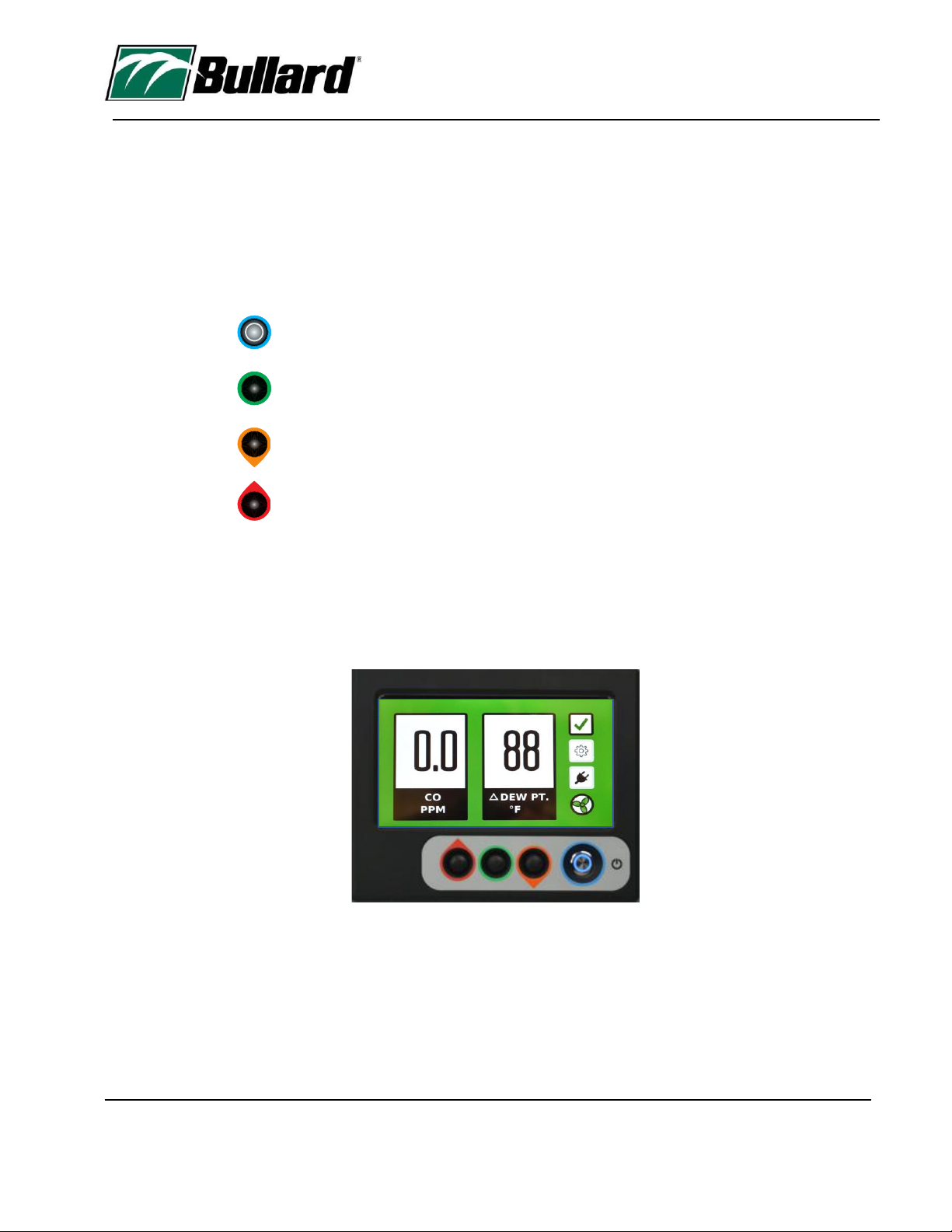
AirGuard uses a computer control menu interface which communicates using a Liquid Crystal Display (LCD). Three
buttons control this interface. These buttons toggle the menu function selection, allow the adjustment of numeric
values, and enter commands.
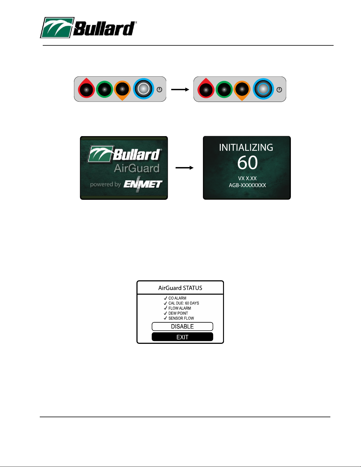
This three-button interface is located directly under the LCD. The buttons are color-coded, (left) red cursor up,
(middle) green enter and (right) orange cursor down. Additionally, the up-down buttons have a droplet point for
direction to assist function direction.
Power On/Off
Green Enter Function
Orange Cursor Down Selection
Red Cursor Up Selection
The main menu has three menu icons that allow access to menu functions and operational changes. From the
primary display, these icons are accessed by using the up/down buttons. The active icon selection has a black
border while the other icons will be grey. The default position is located on the check icon. Toggling the buttons
(orange button) down or (red button) up will change the icon selected position. Upon selection of the desired
function, press the middle green enter button to enter the function.
AirGuardTM
9
www.bullard.com
Menu Function Interface Overview
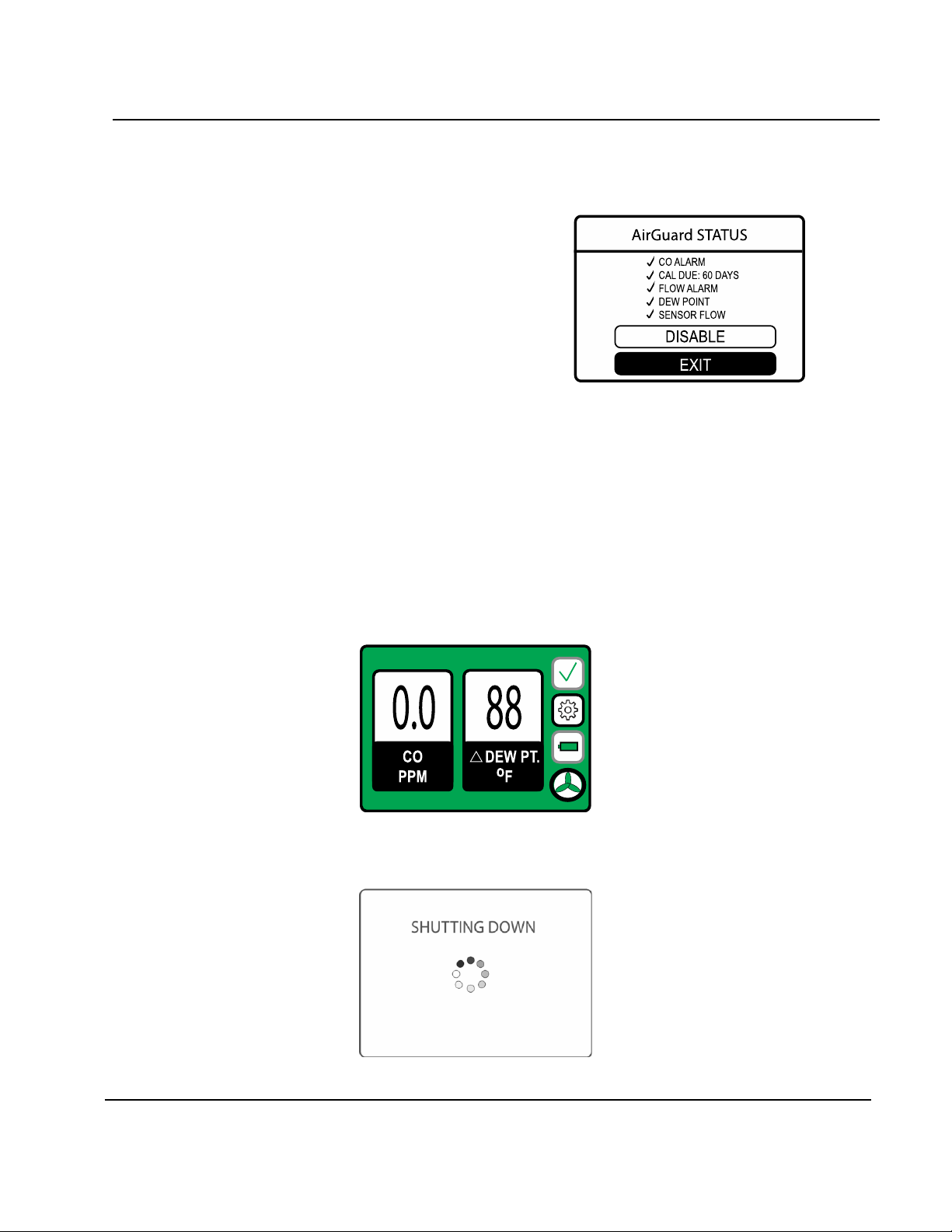
Upon powering on, the AirGuard will display a warmup screen and then “AirGuard Status” screen which
communicates the status of 5 monitored functions.
1. CO Concentration Alarm
2. Calibration Interval Day Count Down
3. CFM Flow Alarm
4. Dew Point Sensor Operation
5. Air Flow to the CO Sensor
This icon has three status functions as defined below.
1. Green Check = System Operation Satisfactory
2. Yellow Check = System Caution or Warning to which user attention is required.
3. Red “X’ = System Fault - AirGuard requires immediate calibration or service and must not be used until
the issue reported is resolved.
Should the status of the AirGuard change during operation, the AirGuard will change the green check symbol along
with the display background. When the check symbol changes color, the operator can press the enter button to
display the AirGuard Status screen which will show the warning or fault encountered.
The alarms can be disabled by selecting the disable function during an activation event.
To get to the main display, the operator must toggle to the exit function to display the main operational screen as
illustrated below.
To power down the AirGuard, press the power button, the shutting down screen will appear, the LCD will turn off
and finally the power button will go dark.

10
www.bullard.com
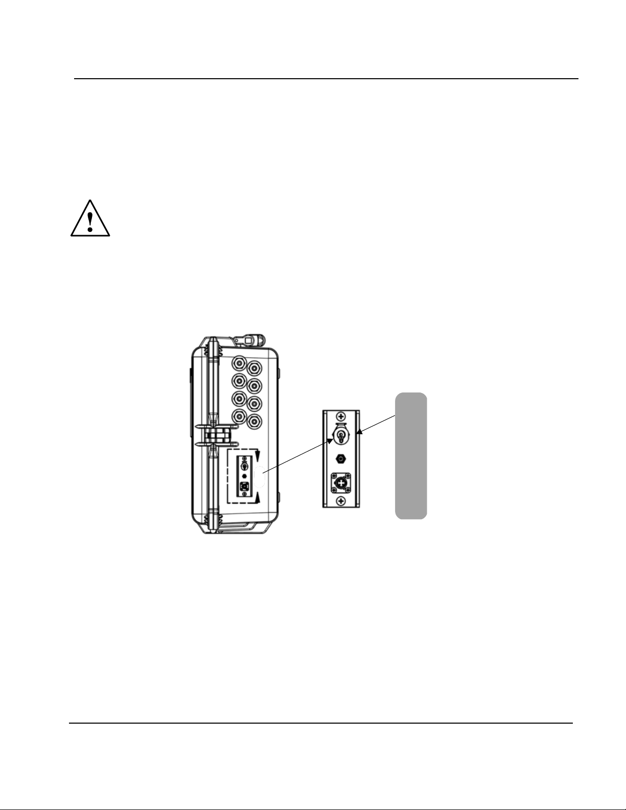
Battery Operation
The AirGuard is a battery-operated portable instrument and should be fully charged before use.
To charge the AirGuard, you must connect the charge connector cable to the charging inlet located on the lower
right side of the instrument. Insert the 2.5mm Ault connector into the female receptacle, secure the connector by
screwing it together, clockwise and then power the charger by connecting to main or wall power 100 to 240VAc
power.
The battery can power the AirGuard for 16 hours of operation.
The AirGuard will indicate a low battery in two ways, one through the main display battery icon turning red. The
other is a screen warning that will appear on the LCD.
If the charger is not connected the LCD will power down to conserve remaining battery power.
LED Position
Red = Charging
Green = Charged
Calibration
Connection
Charger
Connection
Remote
Alarm

AirGuardTM
11
www.bullard.com
Compressor Pneumatic Connections
Prepare to connect the air supply from the compressor to the AirGuard inlet located on the left side of the
instrument.
Caution! 150 pounds is the maximum inlet pressure
Attach the pneumatic hose from the compressor to the AirGuard.
To connect to the AirGuard inlet pull the outside ribbed ring away from the end of the compressor hose and push
the connector into the receptacle port. Release the ribbed connector to complete the connection. Make sure the
connection is secure.
Follow the same process in reverse to disconnect the hose.
Inlet Connection
12
www.bullard.com
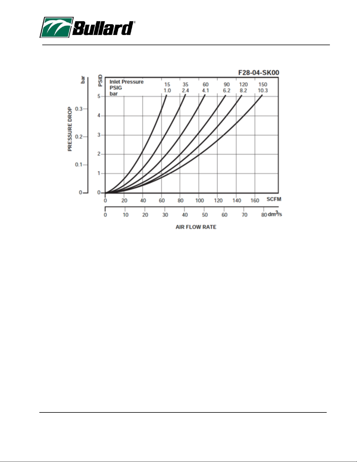
The following chart illustrates the CFM delivered at different inlet pressures.
AirGuardTM
13
www.bullard.com
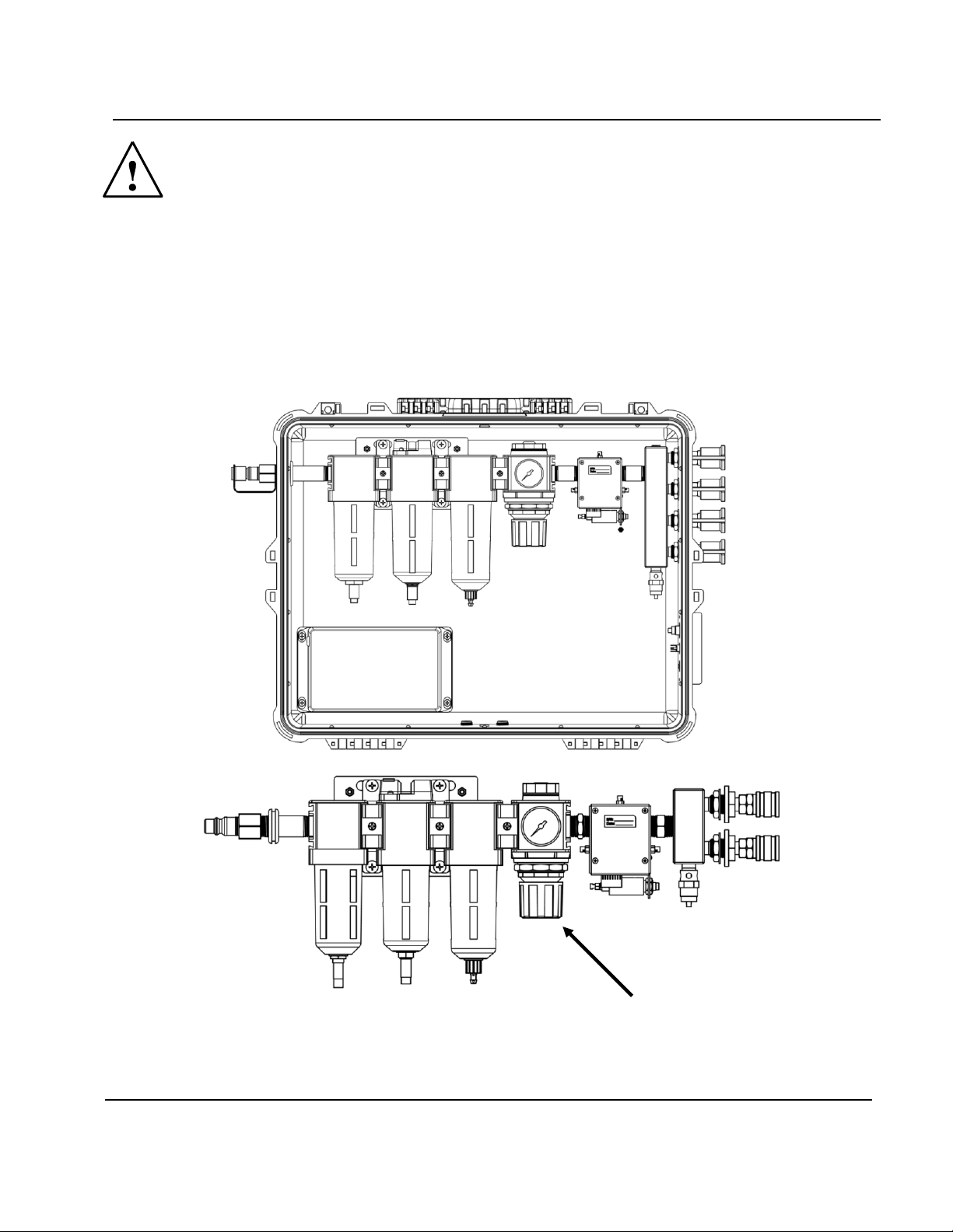
Warning! Maximum Supply inlet pressure cannot exceed 150psi
Review the personal protective equipment instructions to be used with AirGuard. You need to know the pressure
setting required for the correct flow.
Open the enclosure and adjust the delivery pressure by turning the regulator adjustment to the desired pressure
to deliver required SCFM as per the NIOSH approved respirator being used. Clockwise increases the pressure value.
Regulator
Adjustment
Knob
14
www.bullard.com
Start-Up
To turn on the AirGuard, you must press the power on button.
Once pressed, it will illuminate light blue.
During this time the main LCD will activate in ≈ 30 seconds, and the main warm-up in progress screen will display.
After warm-up functions are finished the AirGuard status screen will display a report of 5 key metrics of operation.
1. CO Alarm
2. Calibration Due
3. Flow Alarm
4. Differential Dew Point
5. Sensor Flow
All parameters with a green “check”are satisfactory.
A red "X" will report an unsatisfactory operational status which will need to be corrected or cleared before use. A
yellow “check mark”will appear if there is a caution or warning condition that may require action.
AirGuardTM
15
www.bullard.com
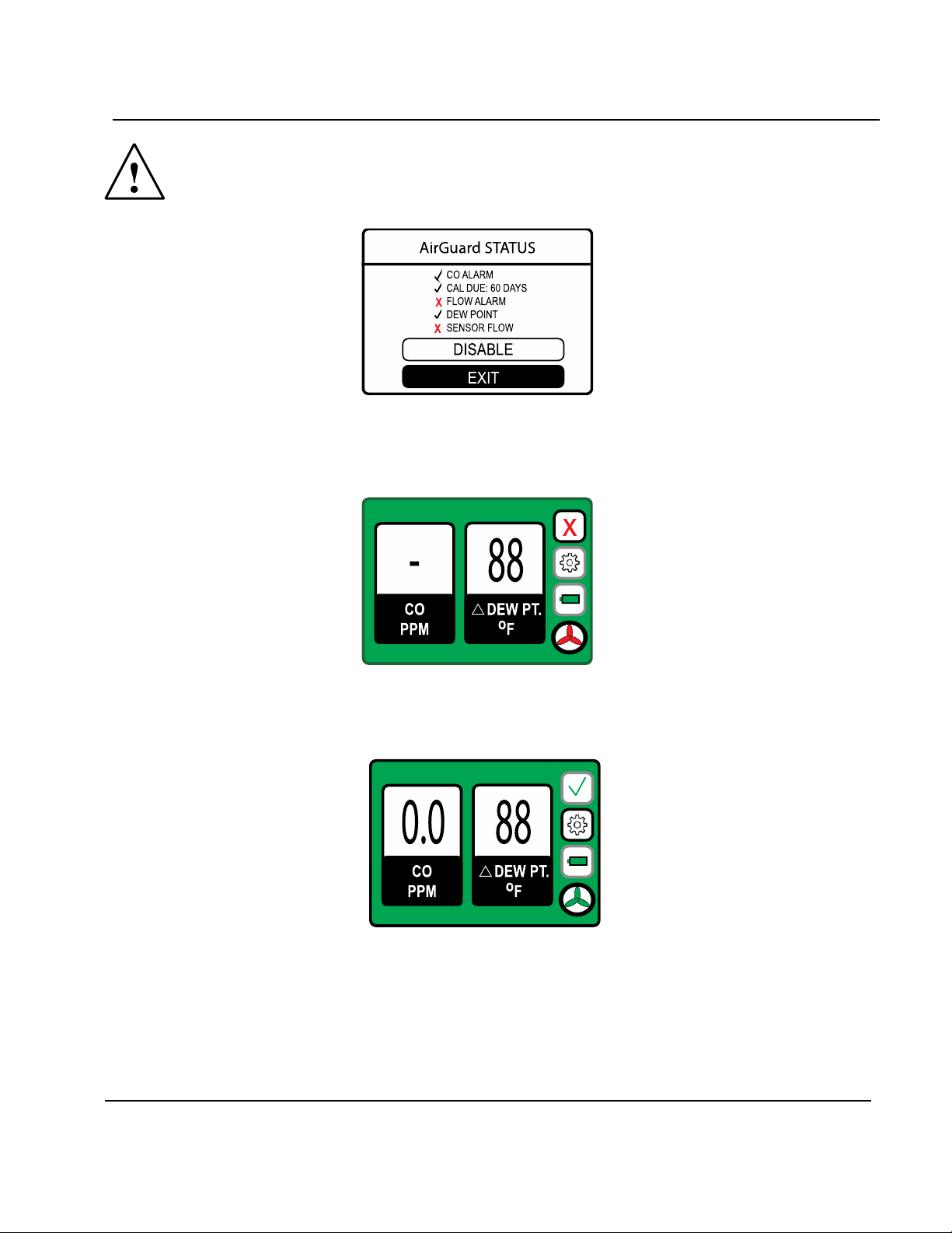
Warning! Below is an example of an AirGuard Status Screen fault message due to no
compressor flow.
After toggling to the exit function, the main operation screen will appear. Under this condition the main screen
will display a dash (-) in place of the carbon monoxide reading. This is a safety measure to ensure the AirGuard is
operating under the correct conditions of compressor flow
Once compressor airflow is established the carbon monoxide value will appear.

16
www.bullard.com
Upon each power up the operator must acknowledge the "AirGuard Status" report before the instrument is ready
for operation. To begin active operation, the user must toggle down to the exit function and press enter.
Next, the main screen will appear indicating the current CO concentration (ppm) and the differential dew point
value in degrees Fahrenheit when connected to compressed air supply. To change the unit to centigrade, refer to
page 22.
Upon display of this screen, the AirGuard is now in normal operational status.
AirGuardTM
17
www.bullard.com
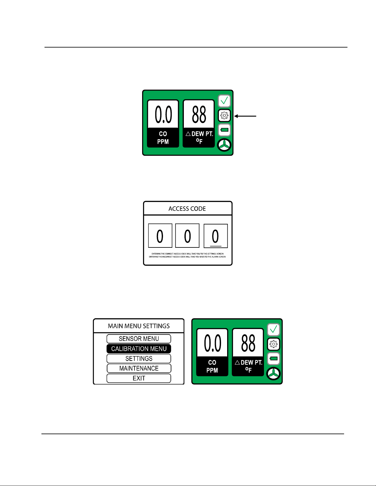
Access Code
To modify the AirGuard functions you must enter an access code.
Toggle to the gear icon by using the down or orange code button. The gear icon outline will appear black and
press enter (green button).
The Access Code Screen will appear.
Enter the assigned access code, the factory pre-set is 2 - 7 - 0.
Entering the correct code will take you to the “Main Menu Settings”screen, if an incorrect code is entered the
main alarm screen will appear.
Gear Icon

18
www.bullard.com
When powered in a no flow condition, the AirGuard will report a system fail “X” and a red fan icon. Additionally,
the system status screen will indicate a flow alarm and sensor flow failures. Once flow is re-established from the
compressor the system status will return to a green check and fan will turn green. The AirGuard system status
screen will display updated information clearing the flow alarm and sensor flow failures to green checks.
Once the gas flow is started, it will take about 4 minutes for the LCD to report the measured gas concentration.
The range of acceptance on a 10 ppm CO standard is 9 ppm to 11 ppm. If the gas concentration is outside of these
values we recommend a complete two-step calibration be performed. Refer to page 23 for step by step calibration
instructions.
AirGuardTM
19
www.bullard.com
Bump Test
It is recommended that the AirGuard is bump checked before use to ensure proper response to a known
calibration standard. Should the reported test values from the bump check not meet the calibration standard
value, ±10% of the reference value, it should be recalibrated.
BULLARD provides a calibration kit for the AirGuard with all the components to complete this test.
(Part Number: AGDCK)
Warning! To perform a bump check, the AirGuard must be disconnected from the
compressor air supply.
Calibration cylinder must be connected to a pre-determined or fixed flow regulator assembly, with a male quick
connect fitting and tubing attached to the regulator.
The calibration cylinder assembly tubing is then attached to the female calibration connection located on the right-
hand side of the instrument and the cylinder is turned on to initiate gas flow.
Calibration
Connection
Charger
Connection
Remote
Alarm
20
www.bullard.com
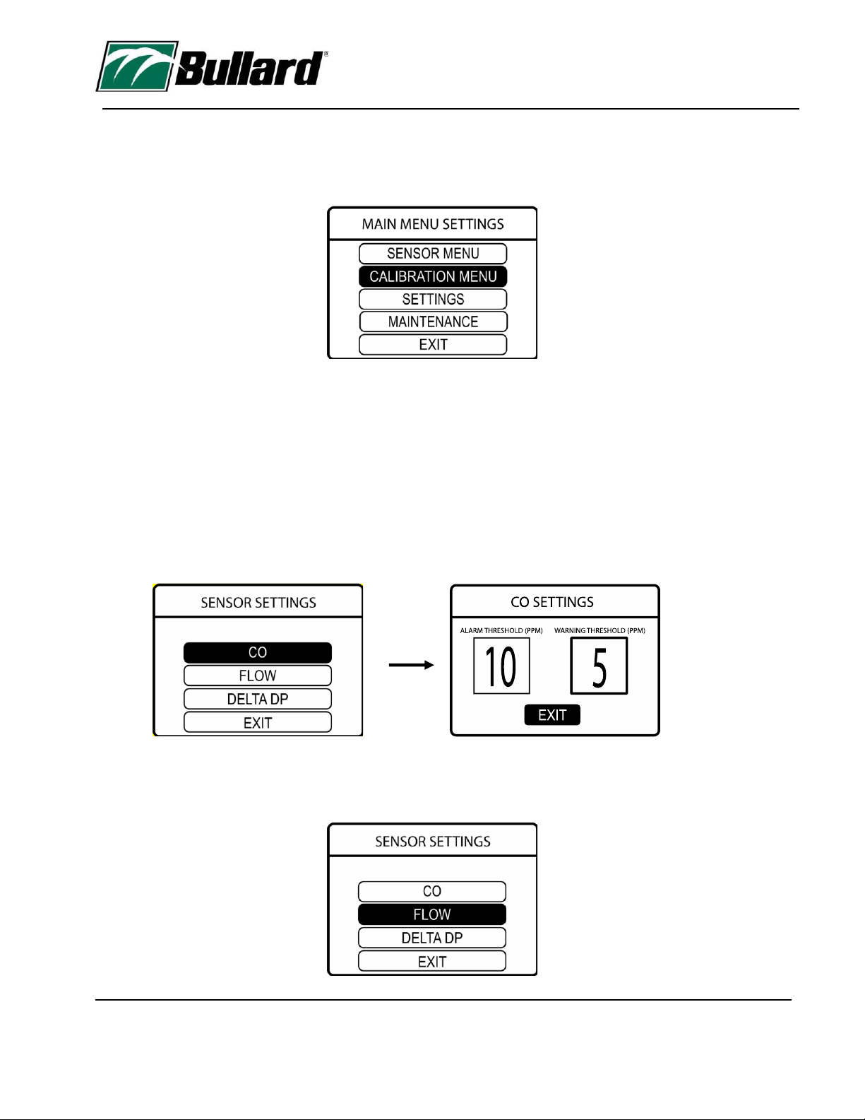
Sensor Menu
The sensor menu allows the operator to adjust function parameters. This includes CFM (flow) alarm and warning
values as well as the audio alarm horn.
The Sensor Settings menu allows adjustment of Air Guard set points such as alarm values, CFM flow value and
delta dew point units.
For the adjustment of number values, the active box containing the number will have a bold border indicating it is
active. To adjust the values, you must use the up and down buttons below the display. You will move to the next
value entry by pressing the enter button or going back to the previous menu.
1. CO (Carbon Monoxide) displays the preset alarm values. These values are user adjustable. The maximum high-
level alarm setting is 10ppm. A value setting higher than 10ppm cannot be entered as per OSHA requirements. A
CO warning alarm (yellow alert) can be set to any value, but cannot be set to the alarm level value.
2. Flow settings adjust both the horn and visual alarms.
Table of contents
Other ENMET Gas Detector manuals


