ENMET EX-5155-MOS User manual

ENMET
680 Fairfield Court
Ann Arbor, MI 48108
734.761.1270 Fax 734.761.3220
www.enmet.com
EX-5155-MOS
Toxic Gas Sensor/Transmitter
Operation Manual

EX-5155
ENMET
Manual Release Date– November 26, 2018
Manual Part No.– 80003-098
P a g e | 1

EX-5155
ENMET
Table of Contents
1.0 INTRODUCTION .................................................................................................................................................................... 4
1.1 Unpack ............................................................................................................................................................................................. 4
1.2 Check Order ..................................................................................................................................................................................... 4
1.3 Serial Numbers................................................................................................................................................................................. 4
2.0 FEATURES OF THE EX-5155-MOS ........................................................................................................................................ 5
3.0 INSTALLATION OF THE EX-5155-MOS ............................................................................................................................. .... 6
3.1 Mounting the EX-5155-MOS Enclosure ......................................................................................................................................... 6
3.2 Wiring the EX-5155-MOS to a Control Unit ................................................................................................................................... 7
4.0 OPERATION OF THE EX-5155-MOS ............................................................................................................................. ......... 9
4.1 Start up ............................................................................................................................................................................................. 9
4.1.1 Typical Start Up.............................................................................................................................................................................................. 9
4.1.2 Alternate Start Up........................................................................................................................................................................................... 9
4.1.3 Purge .............................................................................................................................................................................................................. 9
4.2 Normal Display Mode .................................................................................................................................................................... 10
4.2.1 Alarm Conditions EX-5155-MOS ................................................................................................................................................................. 10
5.0 MAINTENANCE OF THE EX-5155-MOS ............................................................................................................................... 11
5.1 Maintenance Menu ......................................................................................................................................................................... 11
5.2 Calibration of the EX-5155-MOS .................................................................................................................................................. 12
5.2.1 Zero Adjust....................................................................................................................................................................................................14
5.2.2 Gas Span....................................................................................................................................................................................................... 14
5.2.3 Exit Maintenance Menu ................................................................................................................................................................................ 14
5.3 Heater Voltage Settings ................................................................................................................................................................. 16
5.4 Sensor Replacement ....................................................................................................................................................................... 16
6.0 REPLACEMENT PART NUMBERS ......................................................................................................................................... 17
List of Figures and Tables
Figure 1: EX-5155-MOS Features............................................................................................................................................... 5
Figure 2: EX-5155-MOS Mounting Dimensions........................................................................................................................... 6
Figure 3: Terminal Positions EX
-5155-MOS Sensor/Transmitter................................................................................................... 8
Table 1: EX
-5155-MOS maintenance Menus Sequence.............................................................................................................. 11
Figure 4: Calibration Adapter EX
-5155-MOS Sensor/Transmitter................................................................................................ 12
Table 3: Examples of
Standard and Non-Standard Calibration Gas.............................................................................................. 13
Table 2: Calibration Time
......................................................................................................................................................... 14
Figure 5: EX
-5155-MOS Maintenance Menu Flow chart............................................................................................................. 16
Figure 6: Sensor Replacement ............................................................................................................................. ...................... 16
Reference information:
N
OTE
: [important information about use of instrument– if not followed may have to redo some steps.]
CAUTION:
[affects equipment– if not followed may cause damage to instrument, sensor etc…]
WARNING
: [affects personnel safety– if not followed may cause bodily injury or death.]
Manual Release Date – November 26, 2018
Manual Part No. – 80003-098
P a g e | 2

EX-5155
ENMET
Manual Release Date – November 26, 2018
Manual Part No. – 80003-098
P a g e | 3

EX-5155
ENMET
1.0 Introduction
The
ENMET
EX-5155-MOS sensor/transmitters (S/T) is a3-wire, 24 V
DC
4-20mA S/T for the detection of toxic gas, utilizing a
Metal Oxide Semiconductor (MOS) sensor. TheEX-5155-MOS
is meant to be used in conjunction with an appropriate power supply
and
controller
. The
ENMET
EX-5155-MOS
sensor/transmitter has been designed and approved to be used in a Class I, Div. 1,
Groups B, C, D, classified areas. The approval was issued by CSA International.
NOTE:
All specifications stated in this manual may change without notice.
1.1 Unpack
Unpack the EX-5155-MOS
and examine it for shipping damage. If such damage is observed, notify both
ENMET
customer
service personnel and the commercial carrier involved immediately.
Regarding Damaged Shipments
NOTE:
It is your responsibility to follow these instructions. If they are not followed, the carrier will not honor any claims for
damage.
This shipment was carefully inspected, verified and properly packaged at
ENMET
and delivered to the carrier in good
condition.
When it was picked up by the carrier at
ENMET
, it legally became your company’s property.
If your shipment arrives damaged:
oKeep the items, packing material, and carton “As Is.” Within 5 days of receipt, notify the carrier’s local office and request
immediate inspection of the carton and the contents.
oAfter the inspection and after you have received written acknowledgment of the damage from the carrier, contact
ENMET
Customer Service for return authorization and further instructions. Have your Purchase Order and Sales Order numbers
available.
ENMET
either repairs or replaces damaged equipment and invoices the carrier to the extent of the liability coverage, usually
$100.00. Repair or replacement charges above that value are your company’s responsibility.
The shipping company may offer optional insurance coverage.
ENMET
only insures shipments with the shipping company
when asked to do so in writing by our customer. If you need your shipments insured, please forward a written request to
ENMET
Customer Service.
Regarding Shortages
If there are any shortages or questions regarding this shipment, please notify
ENMET
Customer Service within 5 days of receipt at
the following address:
ENMET
680 Fairfield Court
Ann Arbor, MI 48108
734-761-1270 Fax 734-761-3220
Toll Free: 800-521-2978
1.2 Check Order
Check, the contents of the shipment against the purchase order. Verify that the EX-5155-MOS is received as ordered. [Each EX-
5155-MOS
is labeled with its target gas.] If there are accessories on the order, ascertain that they are present. Check the contents of
calibration kits. Notify
ENMET
customer service personnel of any discrepancy immediately.
1.3 Serial Numbers
Each EX-5155-MO S is serialized. These numbers are on tags on the equipment and are on record in an
ENMET
database.
Manual Release Date – November 26, 2018
Manual Part No. – 80003-098
P a g e | 4

EX-5155
ENMET
2.0 Features of the EX-5155-MOS
SeeFigure 1 for location of features:
Feature
Description
Display
Gain Potentiometer
(POT)
LCD: Indicates the level of gas detected by sensor
POT 1: Display contrast adjustment
POT 2: Does Not apply to MOS, not used
Do not adjust
POT 3: Does Not apply to
MOS, not used
Do not adjust
POT 4: MOS Heater Voltage,
Do not adjust unless advised by
ENMET
LED indicators:
Visual Alarms
Power / Fault Indicator LED, Green / Red
Alarm (3) Indicator Red LED, user adjustable
Magnetic Switches
Sensor
MENU: Advances the instrument display through menus (Zero, Span, Exit)
SELECT
: Selects the Zero, Span, Exit menu or sets proper calibration values for Zero or Span
For sensing gas at PPM or LEL levels, see Table 3 for sensor types
Magnetic switches control the instrument maintenance functions. The switch locations are indicated by MENU and SELECT . A
magnetic field pulse is applied by momentarily putting the end of the magnet in proximity to the switch and then removing it.
Referred to as tap. Since the magnetic field penetrates the window, the enclosure cover is not removed in order to perform c
alibration.
Three alarm points are preprogrammed into the EX-5155-MOS
sensor/transmitters. At each alarm point, an LED on the front panel is
activated. These internal alarm settings are independent of the 4-20mA output alarm values that can be set at a controller.
POT 1
Power /Fault
Display
3 Alarm
Indicators
POT 3
POT 4
Menu
Select
MENU
Magnetic switch
POT 2
Internal PCB View
Sensor
Note: POT 2 and POT 3 are not used
with EX-5155 MOS
SELECT
Magnetic switch
Do Not Adjust
External View
Figure 1: EX-5155-MOS Features
Manual Release Date – November 26, 2018
Manual Part No. – 80003-098
P a g e | 5
EX-5155
ENMET
3.0 Installation of the EX-5155-MOS
CAUTION: Area must be declassified during installation.
The
ENMET
EX-5155-MOS gas sensor/transmitter (S/T) is a 3-wire, 24 VDC, 4-20 mA S/T for the detection of toxic gas. The S/T is
meant to be used in conjunction with an appropriate power supply and controller. The
ENMET
EX-5155-MOS
sensor/transmitter has
been designed and approved to be used in a Class I, Div. 1, Groups B, C, D, classified areas. The approval was issued by CSA
International. Appropriate wiring, conduit and fittings are required for proper installation in a explosion proof rated environment.
CAUTION:
Since the sensor/transmitter detects gas only at the sensor location, pay attention to the possible sources of gas, the density
of the gas, locations where the gas may be confined and locations where the gas may damage or injure property or
personnel, when choosing locations of sensor/transmitters.
Also, take into consideration environmental factors when decidingon S/T location. Avoid locations where the S/T may be
damaged by liquid immersion, excessive heat or other know hazards. Also, take precautions to insure condensation insid
of the conduit does not enter the S/T.
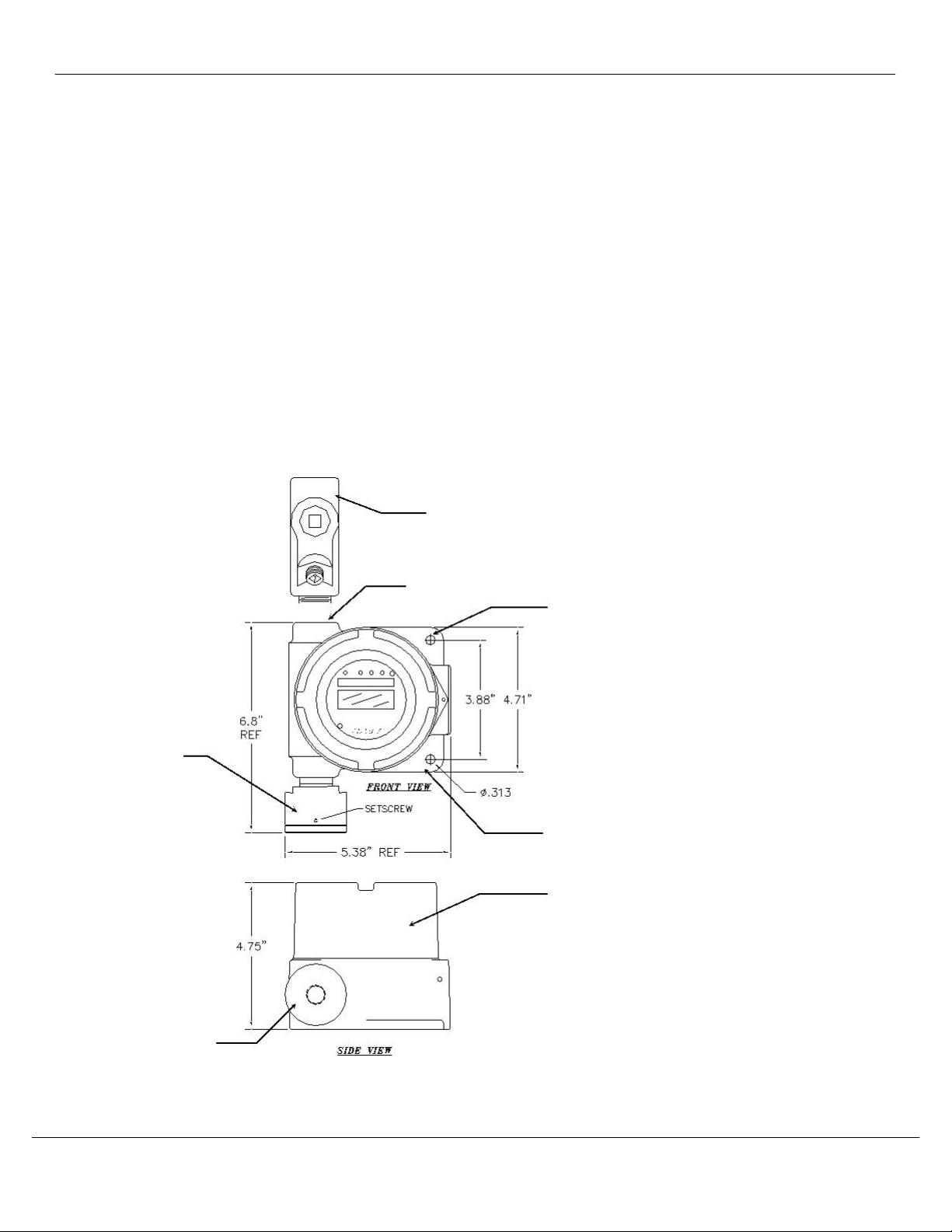
3.1 Mounting the EX-5155-MOS Enclosure
Mount the enclosure, using the two mounting holes provided seeFigure 2. Pay particular attention to the source and density of the
gas being detected when choosing the location. Mount the S/T near the ceiling for lighter than air gases /vapors
and near the floor
for heavier then air gas/vapors. Contact
ENMET
if you have questions regarding your application.
CAUTION:Before connecting S/T to controller remove the power source to controller. Failure to do so may cause damage to
sensitive components.
Optional
Conduit fitting
½NPT female
Mounting Holes
2 places, 0.313
Me
Sel
Sensor
Sensor/Transmitter
Enclosure Top View
Sensor/Transmitter
Enclosure Side View
Sensor
Figure 2: EX-5155-MOS Mounting Dimensions
Manual Release Date – November 26, 2018
Manual Part No. – 80003-098
P a g e | 6
EX-5155
ENMET
3.2 Wiring the EX-5155-MOS to a Control Unit
CAUTION:
Area must be declassified during installation.
Run conduit and 16AWG (1.5MM 2) wires to the enclosure from the power supply and controller. If the
EX-5155-MOS
is installed
in a hazardous location as defined by the National Electrical Code, then
ALL
wiring must be in accordance with the National code
and any local governing codes.
Open the enclosure, and remove the 2 screws that retain the display overlay to the circuit board.
Use caution when removing the over lay. Do not damage the magnetic switches.
Remove the two overlay standoffs and remove the circuit board, exposing the terminal strips on the bottom of the circuit boar
d. Do
not disconnect the circuit board wiring.
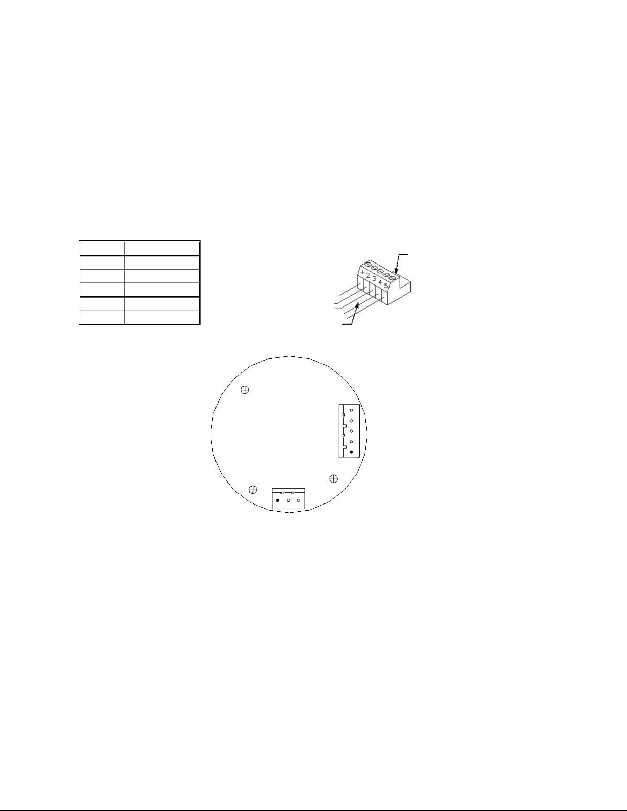
Connect the wires from the controller (power supply) to the supplied J4 plug then attach to J4 terminal.
Connect the wires from the sensor to the supplied J8 plug then attach to the J8 terminal.
SeeFigure 3 for locations
J4 PLUG – TERMINAL TO CONTROLLER WIRING
Position
Function
24 V
DC power
GND
To J4
1 +
2
3
4 - 20 mA out
RS
-485 D+
RS-485 D–
4*
5*
Plug J4
Wires to
*Contact
ENMET
for Modbus address information
Controller
J4
5
4
3
1
2 3
J8
Circuit Board Bottom View
Manual Release Date – November 26, 2018
Manual Part No. – 80003-098
P a g e | 7

EX-5155
ENMET
Display Overlay Screws (2
places)
Display Overlay
Display
Magnetic
Switches (2
places)
Display Overlay Standoffs (2
places)
Printed Circuit Board (PCB)
J4 and J8 Terminals are located on the
bottom side of PCB
Sensor/Transmitter
Enclosure Cutaway View
Display Overlay
Magnetic Switches (2
places)
Printed Circuit Board
(PCB)
Figure 3: Terminal Positions EX-5155-MOS Sensor/Transmitter
When wiring is complete, reassemble theEX-5155-MOS. Use caution when installing the overlay so as not to damage the
magnetic switches. Put the cover back on the S/T
Do Not
apply power to the S/T without the cover in place.
Manual Release Date – November 26, 2018
Manual Part No. – 80003-098
P a g e | 8

EX-5155
ENMET
4.0 Operation of the EX-5155-MOS
It is best to have theEX-5155-MOS
transmitters powered up and operational for 24 hours before applying calibration or test gas to
them.
When theEX-5155-MOS transmitter is first powered up, it goes through a series of momentary screens, which identify the instrumen
model number, serial
number and software revision. After all of the momentary screens have been displayed, the instrument arrives
the Main Gas Display showing the gas concentration and unit of measurement.
Depending on transmitter configuration and calibration condition
, the furthest right character in the display may flash a letter
indicating the instrument status. See the Section 4.1.2 below.
4.1 Start up
4.1.1 Typical Start Up
When power is supplied to the
EX-5155-MOS,
the S/T will display the following sequence of information:
NOTE: Software revision may cause variations of display output.
Example of Display
Function
The instrument: ModelEX-5155-MOS
Note MOS is not displayed
EX-5155
The instrument: Serial Number
76-1256
The instrument: Software Revision
S/W X.X
IF
the right most character is a flashing
W
0ppmW
The instrument is in Warm-up mode
This should last about 1 minute
The Signal Output is held at 4mA duringwarm-up
The instrument: Normal Display Mode
Measurement of target Gas
0ppm
For Toxic Gas
IF the right most character is a flashingC, F, Por R See Section 4.1.2
4.1.2 Alternate Start Up
Depending onEX-5155-MOS
S/T configuration and calibration condition, the furthest right character in the display may flash
a letter indicating the instrument status. See the table below.
Purging occurs automatically for instruments with sensors that require purging. Purge wil
l occur for 5 minutes on instrument
start
-up, followed by a 5-minute recovery period. At the end of the recovery period, the transmitter should be ready for
operation. If additional purge time is required, refer to Section 4.1.3 for more information.
Example of Display(may also display 0 LEC)
Function
IF the right most
character is a flashingC
The last calibration of the instrument was invalid
The instrument must be recalibrated
0ppmC
IF the right most
character is a flashingF
There is a sensor fault
0ppmF
0ppmP
IF the right most
character is a flashingP
The sensor is being purged:
This function is required for certain sensor types
The duration of purge cycle varies with sensor type
TheSignal Output is held at 4mA during purge
The instrument is in Recovery mode after completing the
purge cycle
IF the right most
character is a flashingR
0ppmR
This should take about 5 minutes
4.1.3 Purge
Purging is a function that temporarily increases the sensor heater voltage to clean off contaminants. Some sensors operate at
higher heater voltages where purging is not required. TheEX-5155-MOS
S/T is configured at the factory for the installed
sensor purging requirements.
Purge times vary form 5
– 25 minutes depending on the sensor installed.
Some sensors require additional purge time after start up. Particularly if the sensor is new or the system powered down for
an
extended period of time.
To initiate a purge: Turn the power off and back on. This will initialize a purge cycle.
SeeFigure 5 for the Operational portion of the Maintenance Menu Flow Chart.
Manual Release Date – November 26, 2018
Manual Part No. – 80003-098
P a g e | 9

EX-5155
ENMET
4.2 Normal Display Mode
When theEX-5155-MOS is installed as described in section 3, and in clean air, the POWER green LED is on, the display is lit and
the information on the display is measurement of the target gas detected by theEX-5155-MOS
. The red alarm and fault LEDs are
not lit.
To advan
ce through displays of operational information tap the magnet over the
MENU
button.
NOTE: Software revision may cause variations of display output.
See sequence of operational information below:
Display Measurement of the target gas
Tap the magnet over theMENU button
SELECT
0PPM
MENU
Display indicates Alarm 1 Set point
Tap the magnet over the MENU button
SELECT
SELECT
A1:
A2:
10
20
MENU
MENU
Display indicates Alarm 2 Set point
Tap the magnet over the MENU button
No Function for the
SELECT
button
in this mode
Display indicates Alarm 3 Set point
Tap the magnet over the MENU button
A3:
50
SELECT
S
ELECT
MENU
Display indicates mA Span range
(Full Scale)
mA:
100
Tap the magnet over the MENU button
MENU
Display returns to gas measurement
Operational Display Flo w Chart
4.2.1 Alarm Conditions EX-5155-MOS
There are three alarm set points available. These alarm set points can be changed within limits; see the maintenance section
of
this manual for the procedure.
If the gas concentration increases above that of the alarm set point, the associated red LED is lit.
Manual Release Date – November 26, 2018
Manual Part No. – 80003-098
P a g e | 10
EX-5155
ENMET
5.0 Maintenance of the EX-5155-MOS
CAUTION:
Do not open the
EX-5155-MOS
S/T in a classified area.
Do Not Attempt A Span Procedure Without Calibration Gas
Applied to The Sensor
; if this is done, the S/T is forced into a calibration fault mode.
Magnetic switches control the MENU and SELECT functions. The MENU and SELECT switch locations are indicated on the display
panel, see Figure 3.
The
MENU
switch is used to display the various menu options and make incremental changes to numbers such as
alarm points, calibrations gas, etc. The SELECT
switch is used to select that option, set zero or span digit. Most maintenance
functions are controlled by simple taps of the supplied magnet on the transmitter glass, below the MENU
and
SELECT
boxes on the
front panel.
5.1 Maintenance Menu
To enter the maintenance menu hold the magnet over the MENU
switch for 2 to 4 seconds
Table 1indicates the maintenance menu sequence see Figure 5 for a detailed maintenance menu flow chart.
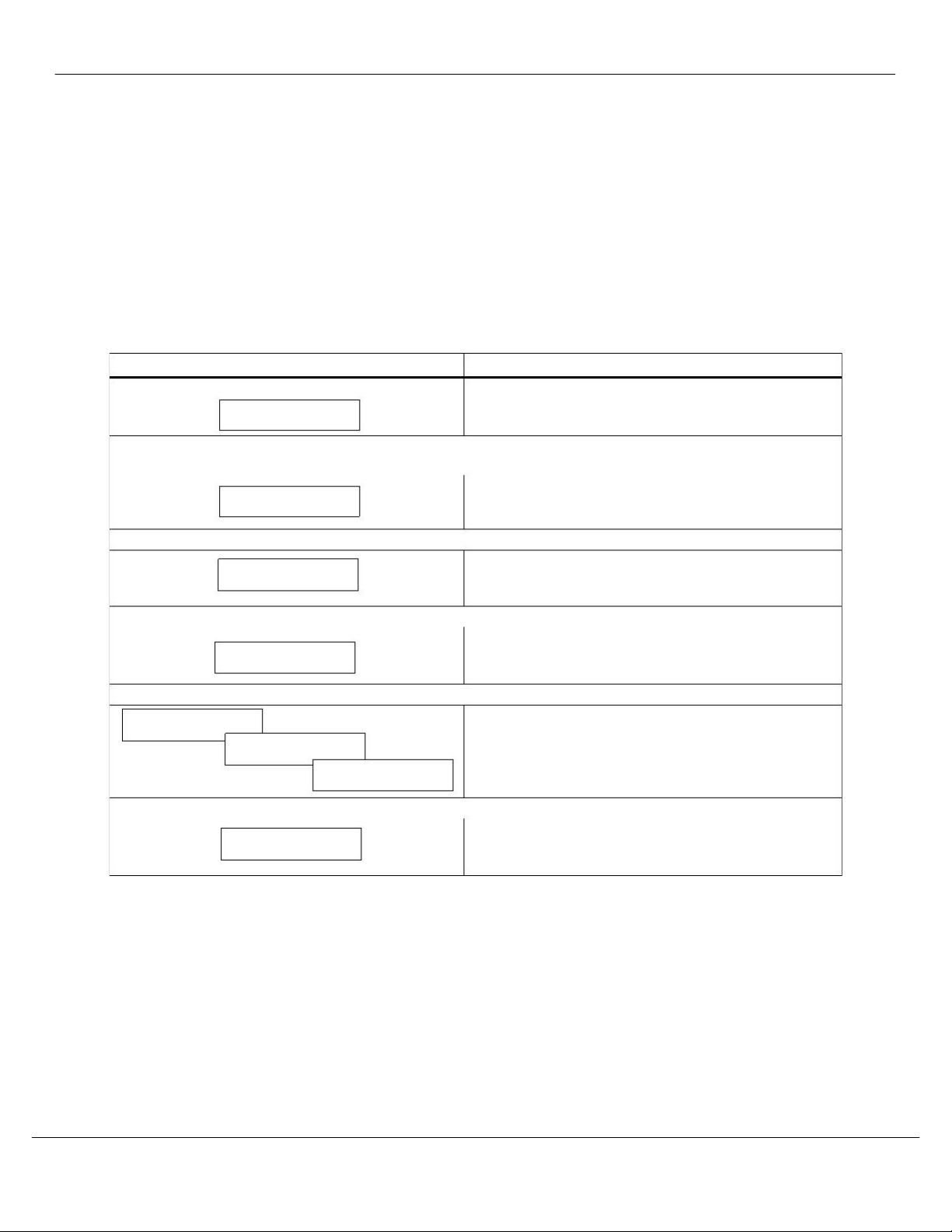
Table 1: EX-5155-MOS maintenance Menus Sequence
Example of Display
Function
Normal Display Mode
Measurement of target gas
5ppm
Hold the magnet overMENU switch for 2– 5 seconds to enter the Maintenance Menu
The Power/Fault LED will flash Green
– Red to indicate the
EX-5155-MOS
is in Maintenance Mode
To exit the maintenance Menu and return to the Normal
Exit
Display Mode:
If intended function Tap the magnet overSELECT switch
Tap the magnet over theMENU
switch to advance to the Zero procedure
For adjusting Zero:
Zero
If intended function Tap the magnet overSELECT switch
Tap the magnet over theMENU switch to advance to the Span procedure
For adjusting the Span:
Span
If intended function Tap the magnet overSELECT switch
Tap the magnet over theMENU switch to advance to each Alarm set point procedures
For adjusting the Alarm 1, 2 and 3 set points:
If Intended function Tap the magnet overSELECT switch
Alarm1
Alarm2
Alarm3
Tap the magnet over theMENU switch to advance the mA Span set point procedure
For adjusting the mA Span set point:
If intended function Tap the magnet overSELECT switch
mA Span
Taping theMENU switch without taping theSELECT switch will allow you to cycle through the menu options.
You must Tap theSELECT
switch in order to change the desired operation.
NOTE: If the S/T fails to respond, the magnet may have become weak and may need to be replaced.
Manual Release Date – November 26, 2018
Manual Part No. – 80003-098
P a g e | 11

EX-5155
ENMET
5.2 Calibration of the EX-5155-MOS
Calibration is the process of setting the instrument up to read accurately when exposed to a target gas. The Zero function s
ets the
clean air reference point and the Span function sets the sensitivity of the instrument.
Initial Calibration: Wait 24 hours after initially supplying power to theEX-5155-MOS sensor/transmitter (S/T) before initial
calibration. The S/T has been pre
-calibrated at the factory, and initial field calibration should result in only fine tuning to circuit,
as well as a way to che
ck that installation is successful. It is not necessary to open the enclosure to make adjustment. The
calibration functions are operated with magnets from outside the enclosure through the
MENU andSELECTswitches. Do Not open
the S/T unless the area is de-classified.
Calibration Zero and Span functions are two separate procedures. They operate independently of each other. It is recommended
that the Zero procedure be done prior to the Span procedure.
ENMET
Corporation recommends at least quarterly calibration of
theEX-5155-MOS transmitters.
Calibration equipment is available from
ENMET
Corporation to calibrate theEX-5155-MOS sensor/transmitters. A calibration
adapter will have a fitting for the gas cylinder on one side
, and a cover to go over the sensor housing on the other.
Generally, a cylinder of 20.9% Oxygen is used to provide a fresh air reference or Zero point for the calibration. Another cy
linder
is used to provide the Span reference point for calibration. De
pending on the instrument calibration, the Span gas may be the same
gas that the instrument is calibrated to display, or it may be another gas, which
ENMET
has found to have a similar response.
Sensors require a humidified calibration gas sample. Fill t
he humidifier bowl, half way up with clean fresh water prior to
attaching the Zero or Span gases. Be careful not to let the humidifier bowl tip, allowing water to enter the gas delivery tu
bing.
See Table 3for standard and Non-standard calibration gases.
Calibration Cover
Select
Input, for Calibration
or Optional Gas Sampling
Menu
Output, for Gas
Regulator
FROM
R
EGULATOR &
GAS CYLINDER
TO CAL COVER
Gas
Humidifier Top View
NOTE: Gas flow isopposite to arrow on humidifier
Figure 4: Calibration Adapter EX-5155-MOS Sensor/Transmitter
Manual Release Date –November 26, 2018
Manual Part No. – 80003-098
P a g e | 12

EX-5155
ENMET
Table 3: Examples of Standard and Non-Standard Calibration Gas
Gas
Range
Alarm 1*
Alarm 2* Alarm 3*
Sensor
Part
Span
Calibration Gas
Calibration Point
Number
Gas Type/ Standard
Methyl Chloride 0
– 400
PPM
100 PPM
35 PPM
200 PPM
50 PPM
300 PPM
100 PPM
03015-000
03011
-000
100 PPM
Methyl Chloride
100 PPM
Carbon
100 PPM
Methyl Chloride
100 PPM
Carbon
0 – 400
Monoxide
PPM
Carbon Monoxide
Monoxide
100 PPM
Carbon
Monoxide
800 PPM
Hydrogen
Hydrogen
Sulfide
0 – 100
PPM
10 PPM
20 PPM
50 PPM
03015-000
03016
-000
20 PPM
Hydrogen Sulfide
Hydrogen
0 – 1000
PPM
200 PPM
500 PPM
800 PPM
800 PPM
Hydrogen
Gas Type/ Non– Standard
Considered
Special Calibrations
, use for examples only. Consult
ENMET
for specifications and availability.
Ammonia
0 – 300
PPM
150 PPM
300 PPM
300 PPM
03019-000
300 PPM
Ammonia
See Addendum
Ammonia
Calibration
1200 PPM Freon
134
Freon 134A
Freon 12
0 – 2000
PPM
0
– 2000
PPM
500 PPM
500 PPM
1000 PPM
1000 PPM
1500
PPM
1500
PPM
03032-000
03032
-000
2% LEL
Methane
300 PPM
Carbon
1200 PPM Freon
12
Monoxide
2% LEL
Methane
500 PPM
Hydrogen
100 PPM
Methyl Chloride
Freon 22
Acetone
0 – 2000
PPM
0
– 2000
PPM
0
– 200
PPM
500 PPM
500 PPM
25 PPM
1000 PPM
750 PPM
50 PPM
1500
PPM
1000
PPM
03032-000
03016
-000
03015
-000
730 PPM Freon 22
1150 PPM Acetone
Methylene
Chloride
100 PPM
140 PPM
Methylene
Chloride
NOTE
: These internal sensor/transmitter alarms are independent of the 4-20mA Controller alarm point settings.
Manual Release Date -November 26, 2018
Manual Part No. – 80003-098
P a g e | 13

EX-5155
ENMET
5.2.1 Zero Adjust
A ZERO function should be performed only when theEX-5155-MOS sensor/transmitter is exposed to fresh air. If the air at the
sensor is in question, use a cylinder of 20.9% oxygen to provide a clean air reference. Attach the cylinder to the calibrati
on
adapter, fill the humidifier bowl halfway with water and allow gas to flow over the sensor for 3
– 4 minutes.
Enter the maintenance menu by placing the magnet overMENU
switch for 2 to 4 seconds. See
Figure 5, EX-5155-MOS
Maintenance Menu flow chart.
The second menu available is the Zero.
Tap theSELECT switch to perform a Zero.
If the Zero is successful
, Cal OK appears on the display and in 1 – 2 seconds, display will change to Span.
If you wish to Span the sensor Tap the
SELECT
switch you are now ready to apply gas.
Proceed to gas span step 2
If you wish to Exit the maintenance menu, Tap
MENU
switch until Exit is displayed, then tap
SELECT
switch to return to the
instrument Normal Gas Display
If the Zero is Not successful,
sensor is outside of safe parameters to be zeroed, the display will read Bad Zero. Repeat
Section 5.2.1 Zero Adjust making sure to use a cylinder of 20.9% Oxygen.
5.2.2 Gas Span
It is recommended that the Zero Function be performed first.
Enter the maintenance menu. See Figure 5, EX-5155-MOS Maintenance Menu flow chart.
1.
2.
Tap the MENU switch once to show Span on the display.
Tap the SELECT switch to perform a Span procedure. The display will alternate between the calibration gas concentration
and a signal level.
N
OTE
:
You can change the Calibration Gas Level.
HOLD
the magnet over the
SELECT
switch for 2 –4 seconds
The
MENU
s witc h changes digit indicated by underscore cursor
3.
Attach the associated calibration gas cylinder to the regulator and calibration cover. See to Figure 3.
4. Open the valve to apply the calibration gas to the sensor.
5. Watch for the signal level to stabilize. Refer to Table 4 for typical response times.
6.
Once the signal level has stabilized, the
EX-5155-MOS
will automatically lock in the calibration data and:
If the Span is successful, Cal OK appears on the display momentarily, then advances to Alarm 1. Remove calibration gas.
To exit maintenance menu tap the
MENU
switch until Exit appears, then tap the
SELECT
switch.
If the sensor is outside of acceptable parameters, Bad Span is displayed momentarily, then returns to Span.
Remove calibration gas. Tap the
MENU
switch until Exit appears, then tap the
SELECT
switch. Check span gas and repeat
calibration in 30 – 60 minutes.
If the sensor did not respond to gas, Same mV is displayed momentarily, then returns to Span.
Remove calibration gas, tap the
MENU
switch until Exit appears, then tap the
SELECT
switch and try calibration again in
30-60 minutes.
If the sensor will not calibrate See Section 5.4.
NOTE: Some software revisions require the
SELECT
switch be tapped to accept the signal.
7. Calibration is complete.
Table 2: Calibration Time
Sensor Type
Calibration Gas Concentration
Calibration Gas Application Time
MOS
PPM
3 – 4 minutes
5.2.3Exit Maintenance Menu
Exit maintenance, by tapping on the MENU
switch until Exit appears on the display. Tap the
SELECT
switch to return to the
instrument Normal Gas Display.
Manual Release Date – November 26, 2018
Manual Part No. – 80003-098
P a g e | 14
EX-5155
ENMET
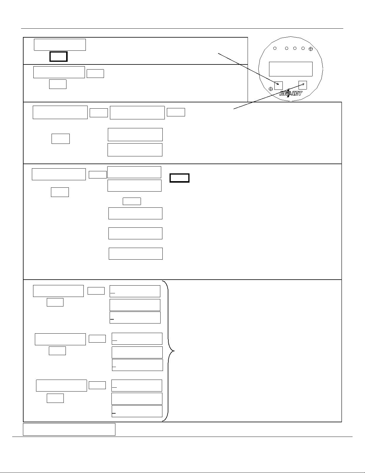
Normal Display Mode
5ppm
HOLD the magnet over theMENU switch for 2– 4 seconds
to enter the Maintenance Menus
MENU
S
ELECT
Tap theSELECT switch to return to the Normal
Display Mode.
See Section 5.2.3
Exit
Menu
Select
MENU
Tap the magnet over theMENU switch to cycle through Maintenance
Zero
PV:
0
Tap theSELECT switch to initiate Zero adjustment
SELECT
SELECT
If the Zero signal is within Preset Specs the EX-5155-MOS will
display Cal OK,
See Section 5.2.1
If
the Zero signal is not within Preset Specs the EX-5155-MOS will
display Bad ZERO
N
OTE: Some software revisions require the
SELECT
switch be tapped
to accept the signal.
Cal OK
MENU
MENU
OR
Bad ZERO
NOTE: You can change the Calibration Gas Level.
S
ELECT
PV:
0
Span
HOLD the magnet over theSELECT
TheMENU
switch changes digit indicated by underscore cursor
TheSELECT
switch
SELECT
20
switch locks underscored digit and moves to next digit
See Section 5.2.2
SELECT
Cal OK
Apply Calibration Gas until signal value becomes stable (about
1 to 4 minutes) SeeFigure 4
OR
Same mV
If cal is good display will indicate OK or Same
OR
If cal is not within preset “range” display will indicateBad
Sens
Bad Sens
NOTE: Some software revisions require theSELECT switch be
tapped to accept the signal.
To change Alarm set points:
Alarm1
Λ10
SetTDsec
0
SELECT
Tap Menu switch until Alarm to be changed is displayed
Tap Select switch to display the set point
MEN
The MENU switch: changes digit indicated by underscore cursor
The SELECT switch: locks in the underscored digit and moves to
next digit
Alarm2
Λ20
SetTDsec
0
SELECT
If change is not within range display returns to first digit
MEN
If change is within range display moves to Set Time Delay
Use MENU and SELECT switches as above to change time delay.
Between 0 and 5 seconds is allowed
Alarm3
Λ50
SetTDsec
0
If change is within range display moves to next menu
SELECT
MEN
Λ - Indicates increasing alarm
V
- Indicates decreasing alarm
Figure 5: Continued on next page
Manual Release Date – November 26, 2018
Manual Part No. – 80003-098
P a g e | 15
EX-5155
ENMET
100
To change mA Span set point:
Tap the MENU
switch until mA Span is displayed
Tap the SELECT
switch to display the set point
The
MENU
switch changes digit indicated by underscore cursor
The SELECT switch locks underscored digit and moves to next digit
mA Span
SELECT
MENU
To return to Normal Gas Display:
Tap MENU switch until EXIT is displayed
Then tap SELECT switch
Figure 5: EX-5155-MOS Maintenance Menu Flow chart
5.3 Heater Voltage Settings
Heater Voltages are necessary for MOS sensors. They are preset at the factory and should not require field adjustment. Do not
adjust these voltages unless specifically instructed to do so by
ENMET
Corporation Technical Support Staff.
CAUTION:
Improper adjustment of heater voltages can damage sensors voiding any warranties and also alter the operating
characteristics of the sensor in such a way that theEX-5155-MOS may not respond to it’s target gas.
5.4 Sensor Replacement
CAUTION: Area must be declassified during sensor replacement.
Sensors should be replaced when they can no longer be calibrated. Replacement sensor part numbers are listed in Section 6.0of this
manual. If you do not know the proper part number for your sensor, be sure to h
ave the
EX-5155-MOS
serial number available
when contacting your Distributor or
ENMET
Corporation Technical Support.
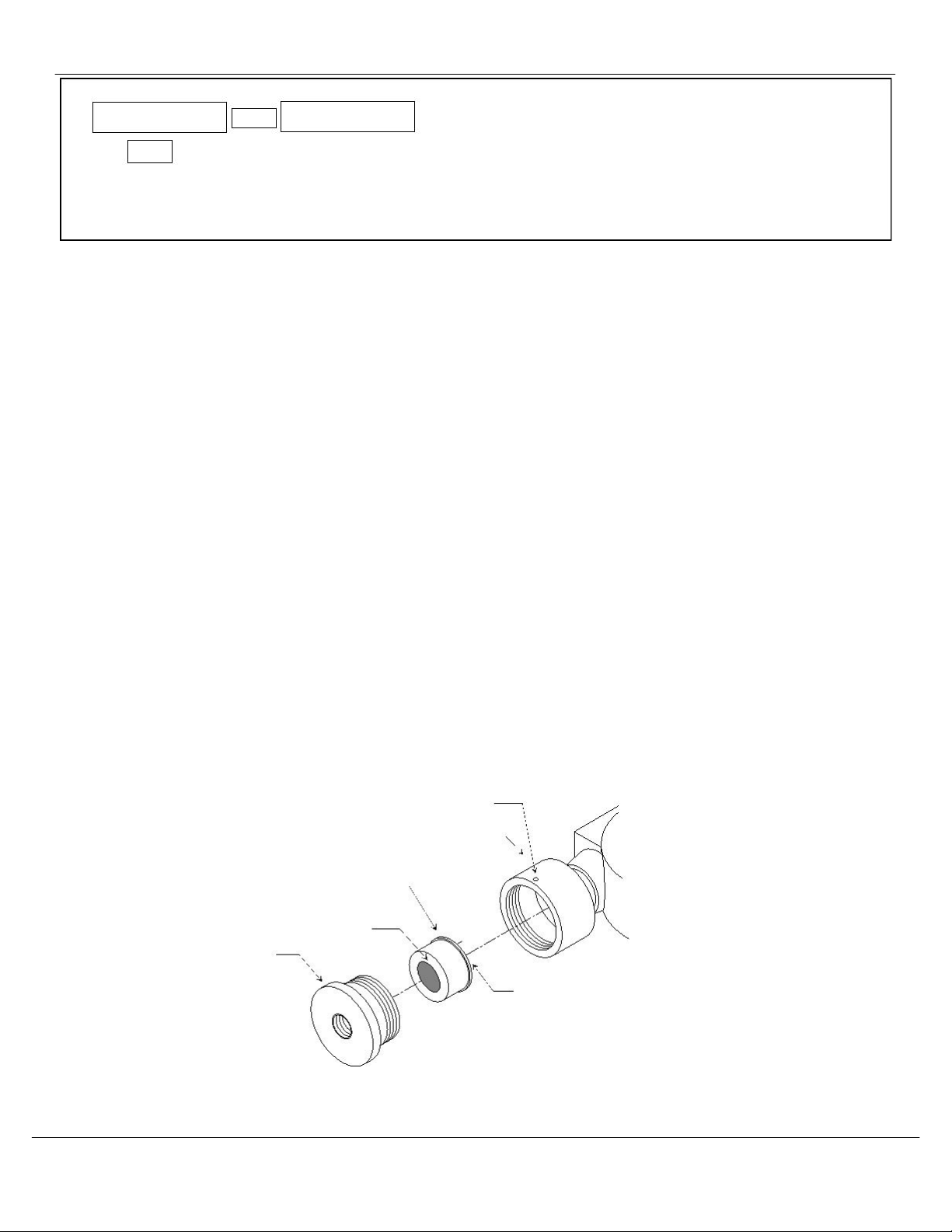
To replace a sensor, it is not necessary to open the transmitter housing.
Remove the set screw from sensor housing base.
Unscrew the sensor housing cover and remove spacer.
Note the orientation of spacer
.
Unplug the sensor form PC Board.
Plug new sensor into PC Board and replace spacer.
Replace spacer with grooved edge toward sensor housing cover
.
Reassemble the sensor housing.
After the new sensor has been installed, it is suggested to allow the sensor to stabilize for 24 hours.
A Factory calibration must be performed.
After entering the Maintenance menu, advance to the Zero menu. Then while viewing the Zero menu, hold the magnet over the
MENU
switch for 2-4 seconds.
After 2
-4 seconds, an F will appear on the far right hand side of the display. The F indicates that the instrument is in Factory mode.
Perform the calibration Zero and Span procedures as outlined in Section 5.2. Be sure that the F is present when selecting th
e Zero
and Span functions.
The Factory calibration sets a
calibration window for future standard instrument calibrations.
Only perform a factory calibration when installing a new sensor.
Set Screw
(0.050 inch, 1.27mm Hex Key)
Sensor Housing Base
Spacer
Note the orientation of spacer for replacement
Grooved edge of spacer toward Sensor Housing Cover
Sensor
Sensor Housing Cover
P C Board
Figure 6: Sensor Replacement
Manual Release Date – November 26, 2018
Manual Part No. – 80003-098
P a g e | 16

EX-5155
ENMET
6.0 Replacement PartNumbers
ENMET
replacement part numbers:
Description
Part Number
For EX-5155-MOS p/n 10014-018
Sensor
03015-000
03016
-000
03018
-000
03019-000
Consult
ENMET
Distributor or
ENMET
Corp for additional sensors
Regulator
Overlay
Magnet
Calibration/Sampling Adapter
03700-008
06000
-058
50030
-001
03700-034
Calibration Gas, Consult
ENMET
Distributor or
ENMET
Corp.
Regulator, Ammonia
03700-005
Manual Release Date – November 26, 2018
Manual Part No. – 80003-098
P a g e | 17

EX-5155
ENMET
7.0 Terms and Conditions
7.1 Ordering Information
Address orders to:
ENMET
Attention: Customer Service Department
680 Fairfield Court
Ann Arbor, MI 48108
Email Orders:[email protected]
Phone: 734
-761-1270
Fax: 734-761-3220
You may also contact our customer service department by email [email protected]. MINIMUM ORDER IS $50.00.
7.2 Shipping Terms
All shipments are F.O.B. ENMET’s facility in Ann Arbor, MI, USA or Bowling Green, KY, USA. Shipping and handlingcharges
are prepaid and added, and must be paid by the customer. Shipping and handling charges may be billed to VISA, MasterCard,
American Express, or to the customer’s preferred carrier account number. Delivery to the carrier constitutes
delivery to the
customer, and risk of loss passes to the customer at that time, however, title shall remain with ENMET until payment is recei
ved in
full. Claims for shortages and damage must be made by the customer to the carrier within 5 days of receipt
.
Refer to section “1.1
Unpack” for m ore information on this matter.
A special service of $50.00, or more, may be assessed on expedited shipments.
NOTE: Calibration gases are classified as Dangerous Goods for transportation purposes, and shipping companies charge a
hazardous material fee for processing the documentation required for handling such items. Also, other restrictions apply to
shipment of Danger Goods by air. Check with
ENMET
for clarification and additional information.
7.3 Payment
Open accounts must be established in advance
with ENMET’s accounting department.
Address Payments to:
ENMET
680 Fairfield Court
Ann Arbor, MI 48108
Phone: 734
-761-1270
We accept payments by VISA, MasterCard, and American Express. Payment by credit card must be specified at time of order
placement. Your credit card will be charged on the date of shipment.
ENMET
invoices for products that are shipped on open account are due and payable 30 days from the date of shipment from the
ENMET
site.
ENMET
may institute collection services should any bona fide invoice remain unpaid with no payment schedule
negotiated by the customer wi
th the
ENMET
Accounting Department. Any cost incurred by
ENMET
for professional collection
services or legal fees to collect on a customer invoice will be added to any future business conducted between
ENMET
and that
customer.
7.4 Warranty Information and Guidelines
Equipment must be returned prepaid to the point of origin, and ENMET will prepay the return transportation charges.
Transportation prepaid by ENMET will be by most economical means (e.g. FedEx Ground). If an expedient means of
transportation is requested during the warranty period, the customer must pay the difference between the most economical mean
s
and the expedient mode. ENMET warrants new instruments to be free from defects in workmanship and material under normal
use
for a calibration and expendable parts such as filters, detector tubes, batteries, etc. In addition, some oxygen cells and other
sensors are limited to a warranty period of six months from date of shipment. Refer to the instrument manual for specific wa
rranty
details. If the inspection by ENMET confirms that the product is defective, it will be repaired or replaced at no charge, wi
thin the
stated limitations, and returned prepaid by FedEx Ground to any location in the United States. ENMET shall not b
e liable for any
loss or damage caused by the improper use or installation of the product. The purchaser indemnifies and holds harmless the
company with respect to any loss or damagers that may arise through the use by the purchaser or others of this eq
uipment. This
warranty is expressly given in lieu of all other warranties, either expressed or implied, including that of merchantability,
and all
other obligations, or liabilities of ENMET which may arise in connection with this equipment. ENMET neith
er assumes nor
authorizes any representatives or other persons to assume for it any obligation or liability other than that which is set for
th herein.
If a component is purchased and installed in the field, and fails within the warranty term, it can be
returned to ENMET and will be
replaced, free of charge. If the entire instrument is returned to ENMET with the defective item installed, it will be replac
ed at no
cost, but the instrument will be subject to labor charges at half of the standard rate.
NOTE: When returning an instrument to the ENMET for service:
Manual Release Date – November 26, 2018
Manual Part No.– 80003-098
P a g e | 18

EX-5155
ENMET
o
o
o
o
Be sure to include all paperwork (the “Request for Service” form).
Include any specific instructions.
For warranty service, include the date of purchase.
If you require an Estimate, please contact ENMET.
The “Request for Service” form is on the final page of this manual. This form can be copied or used as needed. For service
requests, outside of the warranty period, please refer to the
“Returning an Instrument for Service Instruction” found later in this
section.
7.5 Return Policy
All returns for credit must be approved by ENMET and identified with a “Return Material Goods” number. Such returns
are subject to a minimum of a $50.00 or
20% restocking fee, whichever is greater.
Approval of equipment for return is fully at
the discretion of ENMET.
All requests for return/exchange must be made no later than 30 days of the original shipping date
from
ENMET
. The actual amount of any resulting credit will not be determined prior to a complete inspection of the equipment
by
ENMET
. Calibration gas cylinders cannot be returned or restocked due to the Department of Transportation refill restrictions.
Air Filtration Systems (AFS series &
parts) cannot be returned or restocked because their internal surfaces and filters are not
amenable to re
-inspection.
Certain products, such as stationary systems, or instruments with custom sensor configuration (non-standard) are built to
order, and cannot be returned.
Cancellation of orders for custom-built products, prior to shipment, will result in the assessment
of a cancellation fee. The amount of the cancellation fee will be based upon the size and complexity of the order, and the
percentage of total cost expended prior to cancellation.
7.6 Returning an Instrument for Service Instructions
Contact the ENMET Service Department for all service requests.
Phone: 734-761-1270
Email: repair@enmet.com
Fill out the “Service Request Form” found at the end of this manual and return with your instrument for all needs. Please send
your instrument for service to the site in which the product was purchased.
A new “Service Request Form” may be requested if
the one found in the manual is not available. All instruments should be shipped prepaid to ENMET.
Address for Service:
Michigan Location:
ENMET
Attention: Service Department
680 Fairfield Court
Ann Arbor, MI 48108
Kentucky Location:
ENMET
62 Corporate Court
Bowling Green, KY 42103
Providing the “Service Request Form” assists in the expedient service and return of your unit and failure
to provide this information can result in processing delays.
ENMET
charges a one hour minimum billing for all approved repairs
with additional time billed to the closest tenth of an hour. All instruments sent to
ENMET
are subject to a minimum evaluation
fee, even if returned unrepaired. Unclaimed instruments that
ENMET
has received without appropriate paperwork or attempts to
advise repair costs that have been unanswered after a period of 60 days may, be disposed of or returned unrepaired COD and th
e
customer will be expected to pay the evaluation fee. Serviced instruments are returned by UPS/FedEx Ground and are not insure
d
unless otherwise specified. If expedited shipping methods or insurance is required, it must be stated in your paperwork.
NOTE: Warranty of customer installed components.
For Warranty Repairs, please reference
ENMET’s
“Warranty Information and Guidelines” (found earlier in this section).
Manual Release Date – November 26, 2018
Manual Part No. – 80003-098
P a g e | 19
Table of contents
Other ENMET Gas Detector manuals


Popular Gas Detector manuals by other brands


Clemco
Clemco CMS-4 Operation manual

Riken Keiki
Riken Keiki SD-1D-AS operating manual

EsiWelma
EsiWelma Sensigas UCE11 installation instructions

Bühler technologies
Bühler technologies GAS 222.21 AMEX Brief instructions

ATI Technologies
ATI Technologies GasSens O & M Manual

SENSIT Technologies
SENSIT Technologies GOLD G3 instruction manual


