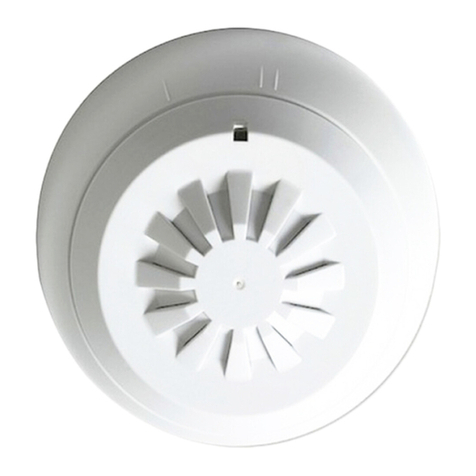
ECP GLD361 User manual

E.C. Products Limited - Head Ofce
EC House, Amberley Way, Hounslow
Middlesex, TW4 6BH, United Kingdom
Tel: +44 (0)20 8569 4100 Fax: +44 (0)20 8569 4111
ECP reserves the right to change the information contained in this datasheet as and when required without notice. Users must take care to use the information contained in this leaet. ECP will not
accept the liability for damages, loss and expenses that may be caused by omissions and errors in the information provided.
Ref: ds_GLD_0209 Ver1.0.
Gas Leak Detection GLD
Page 1 of 4
Description
The GLD gas leak detection range is suitable for use in Boiler
Rooms and other Commercial applications to provide safety and
shut down functions in the event of gas leakage.
Control units are available in 1, 2 or 3 channels for connection to
1, 2 or 3 remote sensors. They are mounted in DIN rail housings
with the option of panel or wall mount enclosures.
Output relays to operate auxiliary devices such as Solenoid Gas
Valves or Sirens and fault remote signalling are tted to all units.
Power supply is 230Vac or 12-24Vdc and sensors are available
for both Natural Gas, LPG/Propane and Carbon Monoxide.
Features
1, 2 & 3 channel options●
Audio & visual alarms●
Adjustable alarm sensitivity●
Relay output for gas valves●
Relay outputs for remote alarms●
Auto or manual reset●
Technical Specication
Power Supply: GLD361: 230Vac ±10% @ 50Hz
GLD65*: 12V ±10%
Power Consumption: GLD361: 3VA
GLD65*: 7VA
Relay Outputs: GLD361: 5(1)A @ 250V SPDT
GLD65*: 2 x 5(1)a @ 250V SPDT
Pre-alarm Thresholds: Natural Gas: 0.3% to 0.8%
(3000 to 8000ppm)
LPG: 0.14% to 0.35%
(1400 to 3500ppm)
CO: 0.012% to 0.03%
(120 to 300ppm)
Alarm Thresholds: Natural Gas: 0.5% to 1.25%
(5000 to 12500ppm)
LPG: 0.22% to 0.56%
(2200 to 5600ppm)
CO: 0.02% to 0.05%
(200 to 500ppm)
Sensors: Natural Gas: GLD150
LPG: GLD250
CO: GLD350
Materials: Base – Nylon, Cover – ABS
Ambient: Storage: -25°C to +60°C
Operating: 0°C to +45°C
Order Codes
GLD361 DIN rail Single Channel Gas Leak Detection Controller
GLD651 DIN rail Single Channel Gas Leak Detection Controller
GLD652 DIN rail Two Channel Gas Leak Detection Controller
GLD653 DIN rail Three Channel Gas Leak Detection Controller
GLD655 Panel Mounting Kit
GLD150 Natural Gas Sensor
GLD250 Propane/LPG Sensor
GLD350 Carbon Monoxide Sensor
Installation
Detector
The detector must be sited in a dry space in which the relevant
ambient limits shown in the Technical Specication are observed.
If sited in a space classied as “Dangerous” it must be installed
in a cabinet for electrical devices constructed according to the
regulations in force for the danger class involved.
The controller can be installed on a DIN rail or in a DIN
modular enclosure.
Sensors
The correct siting of the sensors is essential for efcient
operation and depends on the type of gas to be monitored and
its density in respect of air:
Methane-natural gas (light): 10…50 cm from the ceiling
LPG-propane (heavy): 10…50 cm. from the oor
CO-carbon monoxide: 150…200 cm. from the oor
It is advisable to position the sensors at a certain distance from
the gas appliances so as to avoid triggering unnecessary alarms:
Boilers & caloriers : 1…2 meters
Gas cookers : 2…3 meters
Shut-off solenoid valve
This must be installed on the gas feed pipe, possibly outside the
space controlled, in a place which is easily accessible and is
protected from bad weather.
In LPG installations the valve must be installed downstream of
the pressure reducing valve (30 ... 40 mbar).

Ref: ds_GLD_0209 Ver1.0.
Gas Leak Detection GLD
Page 2 of 4
E.C. Products Limited - Head Ofce
EC House, Amberley Way, Hounslow
Middlesex, TW4 6BH, United Kingdom
Tel: +44 (0)20 8569 4100 Fax: +44 (0)20 8569 4111
ECP reserves the right to change the information contained in this datasheet as and when required without notice. Users must take care to use the information contained in this leaet. ECP will not
accept the liability for damages, loss and expenses that may be caused by omissions and errors in the information provided.
Wiring
Separate base and cover1.
Mount base on DIN rail and check that the securing elements2.
hold it rmly in place.
Carry out the wiring according to the diagram and in3.
observance of the regulations in force, using cables of:
– 1.5 mm2 for power and relay control outputs
– 1 mm2 for sensor with maximum distance of 50 meters or
1.5 mm2 with maximum distance of 75 meters.
Carry out “Link functions” to adapt detector to type of 4.
operational control.
Switch on power (230 V ~) and check the voltage across5.
terminals L and N
Switch off power, replace cover on base and secure it with the6.
two screws supplied.
You are advised not to insert more than two cables in a single7.
terminal of the detector and if necessary to use external
junction boxes.
GLD361
B– Gas sensor
Y1– N.O. solenoid valve with manual reset
Y2– N.C. solenoid valve
Y3– N.C. solenoid valve with manual reset
M– Aeration fan
Link functions:
M - F1 without link = internal buzzer enabled
with link = internal buzzer disabled
F2 - F3 without link = relay normally energised; in presence of
gas de-energised
with link = relay normally de-energised; in presence
of gas energised
F3 - F4 without link = relay with latching alarm
with link = relay with non-latching alarm
Warning: Before changing link positions switch off power supply
GLD65x
B – Gas sensor
Y1 – N.O. solenoid valve with reset 230 V ~
Y2 – N.O. solenoid valve with reset 12 V –
M – Aeration fan
h1 – Blinking 230 V~
h2 – Siren 230 V~
h3 – Blinking 12 V~
h4 – Siren 12 V~
Link functions:
M- F1 without link = Internal buzzer and external alarm activated
with link = internal buzzer and external alarm
disactivated
F2 - F3 without link = relay normally energised; in presence of
gas de-energised
with link = relay normally de-energised; in presence
of gas energised
F3 - F4 without link = relay with latching alarm
with link = relay with non-latching alarm
B2 - H2 with link = B2 sensor not connected
B3 - H3 with link = B3 sensor not connected
NB: For N.C. valves do not make link F2-F3
Warning: Before changing link positions switch off power supply

Ref: ds_GLD_0209 Ver1.0.
Gas Leak Detection GLD
Page 3 of 4
E.C. Products Limited - Head Ofce
EC House, Amberley Way, Hounslow
Middlesex, TW4 6BH, United Kingdom
Tel: +44 (0)20 8569 4100 Fax: +44 (0)20 8569 4111
ECP reserves the right to change the information contained in this datasheet as and when required without notice. Users must take care to use the information contained in this leaet. ECP will not
accept the liability for damages, loss and expenses that may be caused by omissions and errors in the information provided.
Facias
GLD361
GLD65x
1– Sensitivity potentiometer
2– Power supply LED
3– Fault LED
4– Alarm LED
5– Reset button
OPERATION
The detector, when it is powered (2), remains inactive for 1.5 ... 2
minutes with the FAULT (3) and ALARM (4) LEDs blinking, to give
time to the sensor to become stabilised.
The sensor sends to the detector a signal with a voltage
proportional to the concentration of gas present in the air.
When the concentration exceeds the pre-alarm threshold the
ALARM (4) LED blinks.
When the signal exceeds the alarm threshold the detector, after
a delay of about 20 seconds :
– activates the internal buzzer
– switches on the ALARM (4) LED
– activates the operational control
Pre-alarm and alarm threshold
The alarm threshold for natural gas is about 16% of the LEL
(lower limit of explosivity of the gas in air). This is below the limit
set by the manufacturing standards (20% of LEL). The pre-alarm
threshold is about two thirds of the alarm threshold.
This permits, in the event of an alarm, taking action under
conditions of maximum safety.
Using the SENSITIVITY (1) potentiometer the thresholds can
be adjusted within the limits established by the manufacturing
standards :
Potentiometer towards + = increase in sensitivity
Potentiometer towards – = decrease in sensitivity
Alarm
The alarm status brings about the action of the operational relay :
if normally de-energised (F2 - F3 with link) : relay becomes●
energised,contacts : 1-3 closes, 2-3 opens.
if normally energised (F2 - F3 without link) : relay becomes de-●
energised,contacts : 1-3 opens, 2-3 closes.
It is signalled by :
activation of internal buzzer (only if terminals M - F1 without●
link)
lighting of ALARM (6.4) LED on facia.●
Latching alarm and reset
The detector can be programmed in two ways :
Without latching alarm (F3 - F4 with link) :1.
alarm ceases when concentration of gas returns below●
threshold level
a slow blinking (0.2 seconds On and one second Off) of the●
ALARM (4) LED indicates the alarm status.
To disactivate it use the RESET (5) button (press for 5●
seconds).
With latching alarm (F3 - F4 without link - factory setting) :2.
alarm continues even when concentration of gas returns below●
threshold level
To disactivate it use the RESET (5) button (press for 5 seconds).●
Self-diagnosis
In the event of a fault or of incorrect connection of the sensor the
FAULT (3) or ALARM (4) LED lights.
Type of fault Fault
LED (3)
Alarm
LED(4)
Breakage of sensor self-heating element x
No connection to terminal G x
No connection to terminal B x
No connection to terminal M x
Connections G and B inverted x
Connections G and M inverted x
When the ALARM LED lights up the detector puts the system in
alarm mode.

Ref: ds_GLD_0209 Ver1.0.
Gas Leak Detection GLD
Page 4 of 4
E.C. Products Limited - Head Ofce
EC House, Amberley Way, Hounslow
Middlesex, TW4 6BH, United Kingdom
Tel: +44 (0)20 8569 4100 Fax: +44 (0)20 8569 4111
ECP reserves the right to change the information contained in this datasheet as and when required without notice. Users must take care to use the information contained in this leaet. ECP will not
accept the liability for damages, loss and expenses that may be caused by omissions and errors in the information provided.
COMMISSIONING
Power the detector : LINE (2) LED lights.●
After 1.5 ... 2 minutes the detector is enabled for operation.●
Set SENSITIVITY (1) potentiometer on 0.●
Simulate the presence of gas : release gas from an ordinary●
cigarette lighter near the monitoring sensor.
When the gas concentration reaches the pre-alarm threshold●
the ALARM (4) LED blinks.
When it reaches the alarm threshold, after a delay of about 20●
seconds :
– the ALARM (4) LED lights and remains lit
– the internal buzzer sounds (only if terminals M - F1 are
without link).
– the operational relay closes the shut-off valve or switches on
an aeration fan.
Stop releasing gas : when the gas concentration near the●
sensor falls below the threshold level :
– if the detector is Without latching alarm, the alarm ceases
and the ALARM (4) LED continues to blink slowly until the
RESET (5) button is pressed.
– if With latching alarm, the alarm status continues until the
RESET (5) button is pressed for at least ve seconds.
If the detector controls a valve with manual reset this must be●
re-opened.
Dimensions
1 – Protective cover for electronic components
2 – Base with transformer, relay & terminal blocks
3 – Screws for xing cover- base
4 – DIN rail securing elements
5 – DIN rail release lever
GLD361 GLD65x
1
2
3
4
55
1
2
3
4
3
This manual suits for next models
7
Popular Gas Detector manuals by other brands

Dräger
Dräger X-am 7000 Instructions for use
Honeywell
Honeywell SEARCHLINE EXCEL PLUS Technical manual
Riken Keiki
Riken Keiki FP-31 operating manual
BEINAT
BEINAT GSH900 Installation and user guide

Blackline Safety
Blackline Safety G6 Technical user's manual
Tecnocontrol
Tecnocontrol Beta SE330K Series manual

ATO
ATO ATO-GAS-S4 user manual
S&S Northern
S&S Northern Merlin 1000BH Installation operation & maintenance
Seitron
Seitron SEGUGIO DOUBLE RD XSM1 SE Series instructions
Consilium
Consilium Salwico ST400 H2S Calibration instructions

New Cosmos Electric
New Cosmos Electric KD-12 instruction manual

Solight
Solight 1D37 manual

