EsiWelma® s.r.l. E202.602_En Rev. 2 dated 30/11/2018 Pag. 3/4
Technical Data
Control Unit UCE11
Power supply voltage 24VAC +/- 10%
Frequency 50/60Hz
Power consumption 21VA max (with battery under charge)
Sensor inputs 1 x UR.13/A
Control outputs - Electronic 12VDC (13W max)
- SPDT Relay 250V 5(3)A
Controlled valve type Normally Closed or
Normally Open
Operation logic positive (normally energized relay,
de-energizes in case of alarm / fault)
“VALVE TYPE” Jumper
Valve type NO = Normally Open
NC = Normally Closed
“VALVE MODE” Jumper
Valve output mode CONT = continuous
(for NO type only) PULSE = pulses (1 pulse every 10s)
Optical signals (please refer to functional tables)
Green LED Power presence / test
Yellow LED Sensor / valve / control unit fault
Red LED Gas alarm
Sensor connection length cable 1.5mm2 max 80m
Valve connection length cable 1.5mm2 max 80m
cable 1.5mm2 max 40m (13W)
Battery protection fuse T3.15A 250V 5x20
Dimensions 130 x 106 x 56.5 mm
Protection IP20 – EN60529
Room temperature 0…50°C
Room humidity Max 90% R.H. non condensing
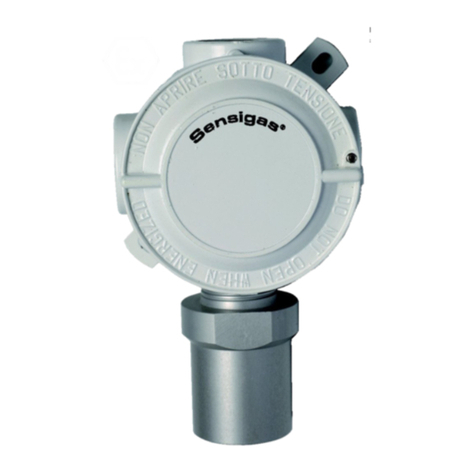
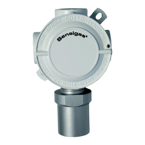
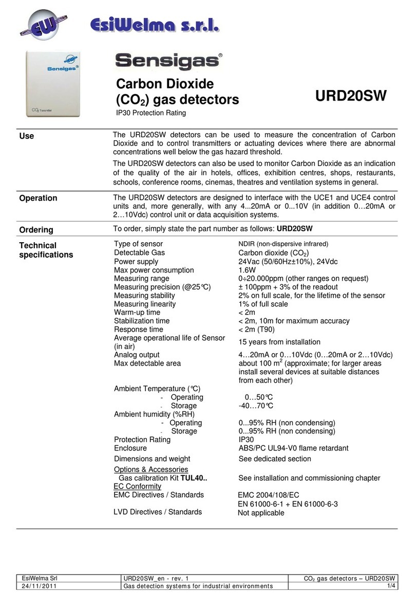
Sensor UR.13/A
Sensing element Tin dioxide semiconductor
URG13/A 20% LEL methane (10000ppm)
URG13.P/A 20% LEL LPG (3720ppm)
URO13/A 200 ppm CO
Protection IP44 (if correctly installed)
5 years from installation date
Room temperature 0…50°C
Room humidity Max 90% R.H. non condensing
Built-in relay
Operation Positive logic (normally energized).
de-energizes in case of alarm / fault
Changeover contact Voltage free 250VAC 5(3)A
Built-in battery charger
Charge voltage 13.8VDC
Charge current 0.5A max
Battery 12VDC 4÷6 Ah (not supplied)
Automatic intervention and current limit
Conformity
Regulations Low Voltage 2014/35/UE
Electromagnetic Compatibility 2014/30/UE
Standards EN50194
EN50270
CAUTION
Lifetime of sensors URG13/A, URG13.P/A e URO13/A is 5
years from installation date. It is necessary to substitute
them systematically before the end of the 5th year of use.
Average lifetime of sensors has been calculated considering a typical
usage in an environment free of pollution substances (gases,
solvents, etc.). A frequent presence or high concentration of these
substances may accelerate normal oxidation process of the sensing
element and consequently shorten its decay time (lifetime).
Functional tables
LEDs status
Functions
Green LED
Yellow LED
Red LED
Sensor preheating ph. (1 min) Flash 1Hz ON ON
TEST phase (3 min) Flash 2Hz ON ON
Normal operation ON ON ON
Gas alarm ON ON Flash 1Hz
Valve fault (*) ON Flash 1Hz ON
Sensor fault ON Flash 1Hz OFF
General fault ON OFF OFF
Output status
Functions
output
EV
(NC valve)
relay
output
Sensor preheating ph. (1 min) Voltage absence De-energized
TEST phase (3 min) Voltage presence Energized
Normal operation Voltage presence Energized
Gas alarm Voltage absence De-energized
Valve fault (*) Voltage absence De-energized
Sensor fault Voltage absence De-energized
General fault Voltage absence De-energized
(*) A valve fault is detected by short circuit (normally closed valve) and open
circuit (normally open valve).
Simultaneousness of 2 or more events causes a combined manage-
ment of LEDs and outputs in accordance with a defined priority.
IMPORTANT
IN CASE OF ALARM FOR GAS LEAK OR CARBON
MONOXYDE PRESENCE ACT AS FOLLOWS:
Cut off all free flames and all gas-supplied devices
Do not switch-on or switch-off electrical lights or any other
electrically-supplied appliance, in order to avoid the
sparkling (cause of explosion for explosive gas)
Close the main valve of gas network or of LPG gas bottle
Open windows and doors to ventilate the rooms
Look for the cause of the alarm, and eliminate it. If you are
not able to find and to eliminate the cause of the alarm,
leave the building, and, from the outside, call for emergency
aids.
Environmental compatibility and disposal
This product was developed and manufactured using materials and
processes which take full account of environmental issues and which
comply with our environmental standards.
Please note the following for disposal at the end of the product life, or
in the event of its replacement:
For disposal, this product is defined as waste from electrical and
electronic equipment (“electronic waste”); do not dispose of it as
household waste. This applies particularly to the PCB assembly.
Observe all current local laws and regulations.
Always aim for maximum re-use of the basic materials at
minimum environmental stress. Observe any notes on materials
and disposal that may be attached to individual components.
Use local depots and waste management companies, or refer to
your supplier or manufacturer to return used products or to
obtain further information on environmental compatibility and
waste disposal.
The UCE11 shipping case can be recycled. Retain it for future
use or in case of product return to the manufacturer.
C NC NO
M


