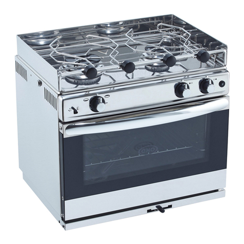
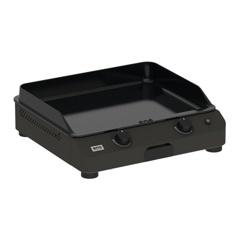
Eno Atoll User manual

eno
MANUFACTUFH
l"l,
95, Rue de la Terraudidre
79 000 NroRT
FRANCE
l:+335492860'15
Fax: + 33 5 49 33 26 84
"Atoll"
Model:0614
C( Bn
"Duo"
Model: 0623 & 0624
AGA 6744G
Australian Gas Approved
INSTRUCTION FOR USE

ENO 1/2 BURNER GAS STOVE
INSTALLATION INSTRUCTIONS
These instructions must be read and undcrstood before installation 'l'o avotd any possibility ofaccident it is essential that
the appliance is installed and operated in accordance wrth thesc lnstructions
This appliance shall only be installcd and serviccd hy an authorizcd pcrson.
DO NOT MODIFY THIS APPLIANCE.
DO NOT USE OR STORE FLAMMABLE MATERIALS IN THE APPLIANCE STORAGE DRAWER OR NEAR
THIS APPLIANCE.
DO NOT SPRAY AEROSOLS IN THE VICINITY OF THIS APPLIANCE WHILE IT IS IN OPERATION.
The Data Label is located on the bunter bracket undenreath thc appliancc A du;rlicate data labcl is supplied to adhcre in an
accessible area next to the appliance. The appliance is surtablc for use with propane gas only.
I _ INSTALLATION AND MAINTENANCE INSTRUCTIONS
Thts appliance is not connected to an exhaust flue: it nust be installed and connected in compliance with the relevant
Installation Rules. Especially respect the regulations concerning verrtilation. fhis appiiance shall only be installed by an
authorised person and in accordance with the manufacturer's installation instructions, local gas fitting regulations, and
municipal building codes, with reference to AS 560 I and any other statutory regulations that are applrcable
- Gas irrstallations on board
IMPORTANT -For marine installations refer to AS560I . scction (r 3 for :mportant specific informalion regarding tlre
installation o1'this app)iance, gas cylindcrs and thejr iocation. prllrrt sysrents etc
For comnrercial nrarine craft, refer to unifonn Shipping Larvs Code. whrch should be read in conjunction with AS5(r0i
- The minimum air inlet neccssary to a proper corrbustion is 2 nrr/h pcr kW power
- Horizontal distance between the applrance arrd the ad.jacent walls shall not be less than 20 mm.
Installatlon and maintenance ofthis appliance have to be carried out by a skilled person in accordance w:th tlre relevant
regulations, in particular:
- Tlre User lTas to comply with Technical and Safety Rules prescriptrons concerning use of inflammable gas and liquefied
lrydrocarbons in houses and outbuildings, stipulating that no unit should be installed in any roonr unless:
- a sufficient air inlet and outlet.
- a mininrum volume of Snr.
- a wjndow with a nrinimunr opening space of 0.40 m,
- a minjnrurrr height of l00 rlm lronr the ground is providcd
- Sanitary regulations
WARNING: When operated, naked flame appliances colrsu:re oxygen and reject exhaust materials,Ventilatio:t is
llecessary wlren appliances are working. Open the ventilation lrolcs designed for this purpose when operating cooker,
WHERE THIS APPLIANCE IS INSTALLED IN MARINE CRAFT OR IN CARAVANS, IT SHALL NOT BE
USED AS A SPACE HEATER.
Never obstruct the openings desrgned for ventrlation.
-This appliance is not suitable for fitment of aftermarket fold-down lids or covers to the
appliance or surrounding structure".
II - INSTALLATION OF THE UNIT (scc t)rarvinss I and 2 on the back cover of this
manual)
The stove is designed to be free standing on a piecc off'urniturc that can rcsist rvithout damage to a penral'tel'tt ternperature
of 90"C. Easily flammable supports must be avoided.
It is tnandatory to leave a space of90 m:r nrinimum behind the rear edge olthe stove and a space of50 mrr between sides
ofthe stove and adjacent vertical parts in order to Iimit increasc tn temnerature

INSTALLATION ON GIMBALS (drawine 1)
a) Fit the gimbals supports O and O on working surface ( see drawing 2 )
b) Fit the gimbals @ and @ on body @ thanks to screws@, washers @ and nuts@ (be
careful with direction of @ and@, the axis of gimbals must be located outwards).
c) Place the whole on supports O and O putting the gimbals axis into openings
d) Possibility of locking the system with key@.
AUSTRALIA 2,75 LPG ( PROPAN )
III - CONNECTION: Suitable for marine use
The gas inlet connection is Iocated behind the appliance.
\Appllanc€
6xil
' -- m""tN R-1-
'rr,! l l^1 lr L ll ll
It
l', L Male 3/8'SAE. 18 UNF
AOI Appro$Bd
flexlblE
hos€ $$ombly
Compre3sior tittlrg
INSTALLATION:
Any connection to the gas supply has to be made with tight mechanical connections or with normalised connections
The connection point is 3/8" SAE18UNF male compression fitting and is located behind the appliance.
A. Tlre cooker can be connected with rigid prpe as specified in AS560l table 6.4 formed rn a loop.
B, The cooker can be connected with an AGA approved flexjble hose assernbly that cornpJres with AS,4'.IZS
I 8(r9. 8nrm ID class B or D. between 600-700rnm long and in accordance with A3560l. The hose should not be sublected
to abrasiolr. kinking or pernranent defonnation and should be able to be inspected for its entire Jenglh Unions conrpatible
with the hose fitting shall be used and tested lor gas leaks.
C. WARNING: Ensure that the hose asserrbly is restrained fronr accidental contact with the flue or flue outlet
ofan under bench oven u,hen the cooker rs in the rnstalled positiorr
1'he supply conl'rectiol'r point shal) be accessible with the appliance installed.
An AGA approved gas cock is recommendcd to bc installed in close proximity to the appliance in an easily accessrble
locatjon. A cornplcte clreck-up ofthc whole installation as described bclow has to be carried out punctually
TIGHTNESS CONTROL
Belore putting the wlrole installation into service with I-PG supply, always make sure that the set-up has been carried out
properlv (from the rcgulator up to the bunrers in shut-offposition) The slrut-offvaives being opened test tlre whole
installation - before frxing the regulator o:r the rubber tubc- with an air pressure equal to three tinres scrvicc pressure but
testing pressure slrall never exceed I 50 rnbar. The whole connectjon has to be considered as tight ifafter a five-nrinute
period (this slrould enable pressure to get balanced), pressure remains constant + 5 mbar during the 1 5 fol)owing minutes.
An appropriate Iiquid, such as soapy water, can be used to detect any possible leakage on tl.re connection part
CAUTION: Do not use any detcrgent liable to contain ammonia: this will damage brass connection parts, Although
the damage may not be obvious at the beginning, fissures and leakage can appear a few months later.
DANGEK NEVER USE A NAKED FLAME TO CHECK TIGHTNESS.
,:,_*,*_l

-
Atier having tested pressure on the whole installalion, every single connected appliance- including burrrer
function - has to be tested while f'unctioning. A visual control ofthe l)ame height on the burners has to be carried out
while all burners are being operated in order make sure the service pressure is suitable fbr each appliance.
BEFORE LEAVING
lgnite all burners both individually and in combination to ensure correct operation ofgas valves, bunrers, flame l'ailure
device and rgnition. Turn gas taps to low 1lame position and observe stability o1'llame lbr each burner both individually
and in combination. When satislled with the operation rnstruct the user with correct method operation. ln case the
appliance fails to operate correctly after all checks have been carried out, refer to the authorised service provider in your
afea
VENTILATION
- must be in accordance with A5560 I - Cas installations section 6.3.7 ln general, pcrmanent openings to olrtslde areas are
required so that the applrance has adequate ventjlation tbr complete combustion ol gas, proper t)ueing and ro nrarnl.ain
temperature of rmmediate surroundings withirr saf'e limits. Operating a gas cookirrg appliance brings abor-rt heat and damp
exhaust in the room where it is being operated. Always make sure that the room is properly ventilated: keep natural
aeration apertures opened or install a mechanical aeration device (hood)
An intensive and prolonged operatron can require an extra ar'ration (by opening a window) or by providing a rnore
eiJicient aeration (hood - ifany - on t'ull on position).
COMB U STI BL E SU RI,-ACES
Any adjoining wall surface situated within 200mm liom the edge ofany hob burner must be a siLitable non combustibie
matenal fbraheightof l50mmfbrtheentrrelengthoithehob Anycombustibleconstructionabovethehotplatemustbe
600mm above the top olthe burner and no construction shall be within 450mm above the top ofthe burner
Pressure -fest Pornt: Ensure that the gas supply pressure at the test pornt is 2.75 kPa.
- A complete check-up should be carried out punctuaily betbre leavrng.
IV - HOW TO REPLACE the BATTERY (electronic isnition device)
- Unscrew battery support cap - at the back olthe appliance
in an anti-clockwise direction, replace with a 1.5 V battery (AA).
- Re-assemble by proceeding in the reverse order.
- lfyou do not use your appliance for a long period, remove battery
IJ.
[(( t ---l
l*r
V - BURNERS IGNITION
Each burner is berng controlled by a valve with control knob. The indicator on the knob indicates valve
position. A syn,bol on the tascia panel indicates the burner posltron.
Each burner is being guided by a tap rvith control knob. The indicator on the knob indicates tap positron. A
symbol on the tascia panel indicates burner position
'lo light a bumer, depress and tum the respectlve control knob to the leli until the knob coincides rvith the large
11ame symbol on the lascia panei (this denotes firll on posrtion). Apply a lighted match or other lighting device to the
bumer (or press eiectronic lgnltion button).
Keep the control knob depressed lor l0 seconds until the tlame lailr,rre devrce is lltted, then release
liburner is not alight, repeat the operation. Wished setting can be obtained by gradually tLlrnrng the control
knob until the indicator coincides with the small flame symbol on the tascia panel
To extinguish the burner, tum the control knob to the right to the Ol'F'position lvhere the knob rr'ill lock in the
OFF position (full symbol)
SYMBOLS: I - Large burner knob 2 - Medium burner knob
qO 10@
I r' A
@

VI - GAS ADJUSTMENT
VII - UTILISATION
HOW'I'O CTIOOSE COOKING US'I't'NSII,S
1'he pan drameter should be suitable with the burner output to avoid any useless energy consumptron.
- O l20to 200 mrn diameter pans with the nrediurn burner
- 0 180 to 260 mrn diameter pans with the large burner
VIII _ MAINTENANCE INSTRUCTIONS
Do not use any abrasrve cleaner or scouring pad.
Your cooker lvill rentain easy to clean ifyou avoid scratching the highly polished stainless steel surfbces.
Clean up spillage of acidic liquids itnrnediately r e lemon.luicr., vlnegar, ere .
Crid, burner caps and cups can be removed and cleaned rvith appropriate cleaners knowing that the burner cups are made
of aluminium. Dry caretully beibre reassembling and make srLre every part is correctly reset.
ABNORMAL OPERATION
While operating, the flame should be mostly blue.
Check that burner parts are correctly repositioned alter cleaning and rlabnormal operation persists have the appliance
serviced by a qualitied person.
ANY OF THE I'OLLOWING ARE CONSIDERED TO BE ABNORMAL OPERATION:
Yellow tipping of the bumer llame
Sooting up olcooking pots, pans etc
Burners not ignrting properly
Burners failing to remain alight
Bunrers extinguished by dralis
Gas valves that are dil.trcult to tum
F'OR WARRANTY SERVICE AND REPLACEMENT PARTS CONTACT:
OCEAN SOLUTIONS INTERNATIONAL
Telephone: (07) 3807 6033
Fax: (07) 3807 6055
Email : sefvice@ocean!olutions.co{n.au
Unit l1- 65 Business Street
YATALA QLD 4207
AUSTRALIA
This appliance is for use with Propane Gas Only
SPECIFICATIONS
GAS BURNER Nominal Output
PRESSURE TPP 2.'75 kPa Propan
Watt NGC Mr/h Jet size (mm )Inpu (sJh
LPC Larp,e "Duo" 2 500 8.5 0.80 8?
Medium "Duo" I 150 59 0.67 2'7
Medium "Atoll" 2 000 65 0'71 45

This appliance is for use with Propane Gas Only
SPECIFICATIONS
CAS BURNER Nominal Output
PRESSURE TPP 2.75 kPa Propan
Watt NGC Mi/h Jet size (mm) lnput (s/h)
LPG Lars.e "Duo" 2 500 tt5 080 182
Mediurn "Duo" I 750 59 0 6'7 127
Medium "Atoll" 2 000 65 07| 145
VI _ GAS ADJUSTMENI'
VII - UTILISATION
HOW'I'O CTIOOSE COOKING US'I'ENSII,S
'l-he pan diameter should be suitable rvith the burner oLLtput to avoid any useless energy consunrption.
- O 120 to 200 rnm dianeter pans rvith the medium burner
- O 180 to 260 mm diameler pans with the large burner
VIII _ MAINTENANCE INSTRUCTIONS
Do not use any abrasive cleaner or scouring pad.
Your cooker rvill renrarn easy to clean ilyou avoid scratching the highly polrshed stainless steel surl'aces.
Clean up spillage ol acidic licluids irnmediately t.e. lenron juice. vrncBar, cre
Crid, burner caps and ctLps can be removed and cleaned with appropriate cieaners knotving that the bumer cups are made
ofaluminium Drycaret'ullybelbrereassemblingandmakesureeverypartiscorrectiyreset.
ABNORMAL OPERATION
While operating, the flame should be mostly blLLe.
Check that burner parts are correctly repositioned atier cleaning and ifabnormal operation persists have the appliance
serviced by a qualilied person.
ANY OF THE FOLLOWING ARE CONSIDERED TO BE ABNORMAL OPERATION:
Yellow tipping ol'the burner tlarre
Sootrng up o1'cooking pots, pans etc.
Burners not igniting properly
Burners l'urlrng t0 rcmaln ullBht
Burners extingurshed by drafts
Gas valves that are ditficult to turn
F'OR WARRANTY SERVICE AND REPLACEMENT PARTS CONTACT:
OCEAN SOLUTIONS INTERNATIONAL
Telephoner (07) 3807 6033
Fax: (07) 3807 6055
E mail : [email protected]
Unit l1- 65 Business Street
YATALA QLD 4207
AUSTRALIA

II{STALLATIOIY DIMENSIOI{S GAS STOVE
"Atoll" "Duo"
- r10
j- oa
I
i
I
,i,
ll I
.I;
rlr
I
I
L.- -,-
1?,r., .. 12,
Ar6._L,s'-\
I
1!0 i30
;4t !,i
l----r
li
tl
i, rh I
ll.l lllsr
tit rlrs'
\'J LP i
lt
rt
ii.- - i
,a- - ?r2 -l -r,o
til
..43 *
I
I
,
B
i
Accessories: Gimble kit for 1 burner Gas Stove Part No KB06l4
R6f: 87959 A
,- l:
SERVICE CONTROLE:
This manual suits for next models
4
Table of contents
Other Eno Cooker manuals
Popular Cooker manuals by other brands

Range Master
Range Master 90 Ceramic Installation and user guide
Proficook
Proficook PC-SV 1159 quick start guide
Master cook
Master cook KGE 3468ZB DYN instruction manual

Range Master
Range Master Infusion 100 Induction User's guide & installation instructions

O.K.
O.K. OFC 11311 A user manual
Range Master
Range Master Classic Deluxe 90 Induction Installation and user guide
