ENOCHS POWER 4000 User manual

SERVICE MANUAL
FOR POWER 4000
ENOCHS
Examining Room Furniture

TABLE OF CONTENTS
2
Item
Page
IMPORTANT Safety Blocking Procedure
3
System Overview
4
Important Safety Information
5
Troubleshooting Problems
6
Access to Table Components
7
Back Cylinder Replacement
8
Lift Cylinder Replacement
9
External Solenoid Replacement
10
Hydraulic Hose Replacement
11
Pump Unit Replacement
12
Installation of Access Panels
14
Electrical System Wiring Diagram
15
Electrical System Schematic
16
Hydraulic System Schematic
17
Foot Pedal Wiring Diagram
18
Maintenance Checklist
19
Parts List
20
Service Log
22

SAFETY BLOCKING PROCEDURE
for ENOCHS Power 4000
3
W A R N I N G
Follow SAFETY BLOCKING PROCEDURE before any hydraulic
maintenance work is initiated.
F a i l u r e t o f o l l o w t h i s i n s t r u c t i o n c o u l d r e s u l t
i n s e r i o u s b o d i l y i n j u r y
D A N G E R
Loosening or disconnecting the hose running from the base of the
lift cylinder to the external solenoid (reference Hydraulic Schematic,
part number 116-42BH1B) will release hydraulic pressure in the lift cylinder
and will cause sudden downward collapse of table.
NEVER work inside pedestal column without safety blocking in place.
SAFETY BLOCKING PROCEDURE:
Required: External Blocking (A)2 - 2x4s cut to 18¾" for use if lift cylinder not working
Internal Blocking (B)2 - ¾" hardwood dowel rod (or equal blocking) cut to 29" length
1. Raise table to maximum height, lower back to flat position and skip to Step 4. If table can not be hydraulically raised, raise back to full
chair position and unplug table. Remove side drawer, free front of right drawer track mount channel and lower for access to the lift
cylinder clevis. Locate and remove clevis key and pin.
2. Locate and remove the bolt connecting the support arm to the couch frame. Allow support arm to lower into table base and lower back of
table to flat position. Lift up seat section to locate and remove the four bolts securing couch to table base. Carefully lift upholstered couch
top off and set safely aside.
3. With assistance, manually raise moveable table section to maximum height and support it between floor and outside shell as shown
above with External Blocking (A)
4. If lift cylinder or hose # 116-42BH2R is being replaced, locate and remove only the top two screws (1-L & 1-R) holding headend sliding
access panel channels in place (see Installation of Access Panels on page 14).
5. Remove the two sliding access panels from footend of table (C) (see Installation of Access Panels on page 14).
6. Place Internal Blocking (B) between lower foot end corners of the pedestal housing and upper cylinder support weldment (see above).
7. Raise moveable section of table and remove external blocking then lower the section so that it is fully supported by the Internal Blocking.
Verify table is firmly supported on Internal Blocking before proceeding with any maintenance or repair.
8. UNPLUG POWER CORD to eliminate possible electrical shock and proceed with specific repair.
(B) Internal Blocking
Place two correct length 3/4” dowel
(or other blocking), inside the housing
between the lower foot end corners of
the pedestal housing and UPPER
cylinder support weldment.
HEYCO® strain relief
Moveable section of table
(A) Exterior Blocking
2x4 cut to 18¾"
Upholstered couch
(D) Remove footend squaring panel.
(C) Remove sliding access panels from table
FOOTEND VIEW OF POWER 4000
(A) Exterior Blocking
2x4 cut to 18¾"

SYSTEM OVERVIEW
4
This manual covers service and repair of the ENOCHS Power 4000 High-Low Examination Table. If you
encounter questions or concerns that are not covered in this manual, contact ENOCHS Examination
Room Furniture - Customer Service at 1-800-428-2305 or Technical Support at 1-800-322-6416, FAX to
317-580-2944 or e-mail to enochs@enochsmed.com.
MAINTENANCE PROCEDURE
WARNING
Follow SAFETY BLOCKING PROCEDURE on page 3
before
any hydraulic maintenance work is initiated.
Failure to follow these instruction could result in serious bodily injury.
OPERATING OVERVIEW
The table height adjustment range is 24" to 40". Back adjustment is from flat to full chair position.
Adjustment is made by operating the appropriate foot control treadle. Other table features include
overload protected dual electrical outlets, storage drawer, warming drawer, pelvic tilt, stirrups, paper roll
holder, irrigation basin and a pull out leg extension.
SYSTEM OVERVIEW
The electro-hydraulic system includes: a 1/3 hp, 120 VAC, bi-directional hydraulic pump unit consisting of
a pump/motor/reservoir assembly, one double acting cylinder with external solenoid low control valve to
adjust table height and one double acting cylinder with internal solenoid valve to adjust back position.
The pump/motor has a built in thermal protection and will temporarily interrupt operation if overheating
occurs.
RECOMMENDED OIL: Manufacturer of system recommends using an ISO 32 or a 10 weight hydraulic
oil. Oil must be industrial grade, non-detergent and mineral based.
Manufacturer of system recommends Mobil DTE 24 (10 wt) or Valvoline 10.
IMPORTANT: DO NOT USE MEDICINAL MINERAL OIL
FILL LEVEL: Oil should be ½"–¾" below fill hole to allow for expansion of oil during system operation.
ELECTRICAL RATING: 115 VAC, 60 Hz, 12 A. DO NOT CONNECT TO OTHER VOLTAGES
MAINTENANCE
Periodically check:
inside of table to make sure no objects have fallen into base of table
hydraulic fluid levels –confirm hydraulic oil level is ½" from fill hole
Every 6 months:
Complete MAINTENANCE CHECKLIST on page 19
Every 12 months:
Lubricate gear bushings and shaft of upper chain drive
If a problem develops, DISCONTINUE USE of the table until a service technician can make repairs.
Keep this manual in a location for access by service technician as reference for correct maintenance and
repair of this product.
IMPORTANT SAFETY INFORMATION
5
Special safety considerations for the maintenance and repair of the Power 4000 are for the protection and safety
of service technician. BEFORE performing any maintenance or repair, carefully read and understand all
instructions and procedure requirements. It is technician’s responsibility to follow maintenance/repair
instructions in this manual.
Failure to follow these instructions could result in bodily injury and/or
product damage.
MAI NTENA NCE PR O C ED URE W A RNIN G
Maintenance personnel must properly secure table with SAFETY BLOCKING before any hydraulic
maintenance work is initiated. Failure to follow this instruction could result in serious bodily injury.
DANGER
The weight of the table’s upper section is supported entirely by hydraulic oil captured in the
bottom section of the lift cylinder and the hose connecting it to the external solenoid cylinder.
Loosening or disconnecting the hose running from the base of the lift cylinder to the
external solenoid (part number 116-42BH1B - see Hydraulic System Schematic page 17)
will release the hydraulic pressure in the lift cylinder and will cause sudden downward
collapse of table.
Follow SAFETY BLOCKING PROCEDURES instructions on page 3 of this manual before proceeding with
any maintenance or repair procedures.
DANGER: ELECTRICAL SHOCK HAZARD
Shock hazard exists when working on table. Unplug power cord from power source when
working on table during all repair procedures to eliminate shock hazard. Replace all covers
upon completion of repair and before power is restored.
CHECK GROUNDING CONTINUITY periodically to ensure safe operation.
Failure to follow this instruction could result in bodily injury and/or product damage
Electrical Rating: 115VAC, 60 Hz, 12 A.
DO NOT CONNECT TABLE to other voltages. Irreversible damage to the electrical
components will occur and bodily injury may result.
USE ONLY a Hospital Grade 115 V receptacle for proper electrical connection.
UNDER NO CIRCUMSTANCES SHOULD HOSPITAL GRADE 115 VOLT CORD PLUG BE
REPLACED WITH OTHER TYPE.
DO NOT USE table if electrical cord is cut, worn, frayed or otherwise damaged.
DO NOT USE table if abnormal sounds are heard during any adjustment.
DO NOT USE extension cord unless NEMA approved for required electrical specifications.
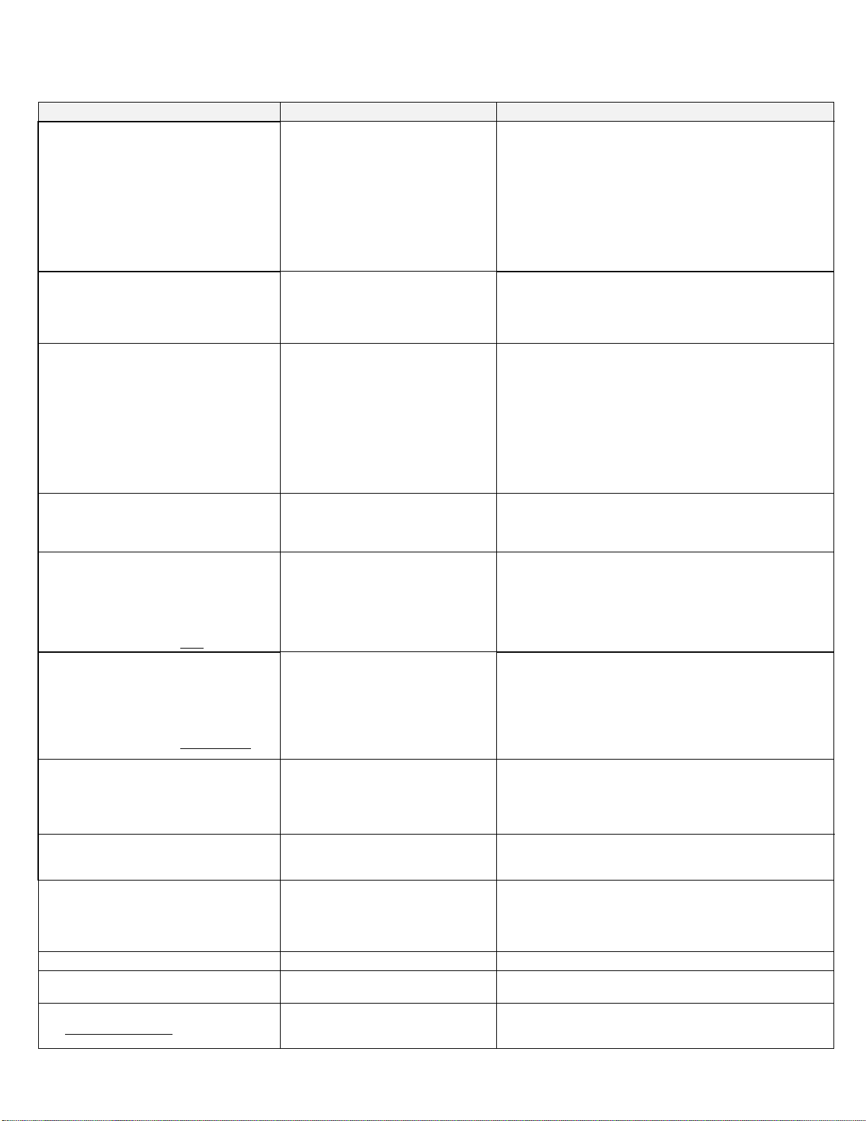
TROUBLE SHOOTING PROBLEMS
6
DESCRIPTION OF PROBLEM
POSSIBLE CAUSE
SOLUTION
Table height will not go up or down but:
motor turns on
back functions up & down
no hydraulic leak noted
foot treadle movement restricted
by debris or damage
OR
external solenoid not working
OR
problem with foot control cord wire or
micro switch
1. re-establish free movement of the treadles
2. confirm treadles making solid contact with micro-switches
1. reference Electrical System Schematic on page 16
2. check continuity of solenoid coil
3. replace bad external solenoid
1. reference Electrical System Schematic on page 16
2. check continuity of white wire in foot control cord
3. confirm micro-switch is activating solenoid
4. replace parts as required
Table is in full down position and will not
go up but:
motor turns on
back moves slowly or not at all
hydraulic leak noted
cylinder, hose or hose
connection leaking hydraulic oil
1. locate leak and replace required part
Back not responding to foot control but:
motor turns on
table height works up and down
no hydraulic leak noted
movement of foot switch treadle
restricted by debris or damage
OR
cylinder solenoid not working
OR
problem with foot control cord wire or
micro switch
1. re-establish free movement of the switch treadles
2. confirm foot pedal is making solid contact micro-switch
1. reference Electrical System Schematic on page 16
2. check continuity of solenoid coil
3. replace cylinder
1. reference Electrical System Schematic on page 16
2. check continuity of black-on-white wire in foot control cord
3. confirm micro-switch is activating solenoid
4. replace parts as required
Back will not go up or down but:
motor turns on
height will not work or is sluggish
hydraulic leaks noted
cylinder, hose or hose
connection leaking hydraulic oil
1. locate leak point
2. replace required part
Table’s height & back will not go up or
down but:
foot control micro switches clicking
when foot switches are activated
motor not turning on
no hydraulic leak noted
electrical outlets work
motor has overheated due to
prolonged continuous operation
OR
foot control cord wire problem
OR
Motor problem
1. wait for unit to cool down
2. motor protection re-sets automatically
1. reference Electrical System Schematic on page 16
2. trace circuit to isolate problem
3. repair as required
Table’s height & back will not go up or
down but:
foot control micro switches clicking
when foot switches are activated
motor not turning on
no hydraulic leak noted
electrical outlets DO NOT work
power source failure
OR
power cord damaged
1. check building power source
1. replace cord
Table will not lift patient but:
motor turns on
table acts like it wants to work
back functions up & down
no hydraulic leak noted
patient to heavy
OR
oil supply may be low
1. don’t use table with this size patient
1. check oil level in reservoir.
2. refill with recommended hydraulic oil to correct level
Table running slow or functions incomplete
oil supply low due to leak in cylinder,
hose or hose connection
1. check oil level in reservoir
2. if level is low, locate and repair any oil leaks
3. refill with recommended hydraulic oil to recommended level
Height and back moves in only one direction
–up or down.
motor/pump not changing direction flow
OR
Wire in foot control cord damaged or
disconnected
1. replace pump unit
1. reference Electrical System Schematic on page 16
2. check continuity of blue or red foot control wires
3. repair as needed
Cylinder drifts down , won’t hold position
bad solenoid valve
1. replace back cylinder or external solenoid for lift cylinder
110 V. outlet not working but:
all other table functions work
damaged outlet or loose wire
1. tighten connections or replace duplex receptacle
Hydraulic system makes squealing noise at
the end of cylinder stroke but:
no hydraulic leak noted
leaving foot to long on pedal after unit
reaches maximum stroke
1. take foot off pedal as soon as stroke is complete

TROUBLE SHOOTING PROBLEMS
7
DESCRIPTION OF PROBLEM
POSSIBLE CAUSE
SOLUTION
Hydraulic system makes squealing noise
during adjustment but:
no hydraulic leak noted
oil supply may be low
1. check oil level in reservoir.
2. refill with recommended hydraulic oil to correct level.
Clunking sounds are heard during table’s
height adjustment but:
all other tables functions working
sliding side access panels are not
positioned correctly
1. remove footend access panels, check to make sure Nylatron
edging is securely in place and reinsert panels into slides
2. reference Installation of Access Panels on page 14
Table makes scraping or grinding noises
during height adjustment but:
back does not make noise
no hydraulic leak noted
lift chains and shaft bearings require
lubrication
1. remove side drawer, locate chains and shaft
2. spray roller chains and shaft bushings with silicone lubricant
Table functions are erratic and noisy but
no hydraulic leak noted
air in hydraulic system
1. run table through all functions several times
2. loosen fill hole cap on reservoir to release air
Table wobbles or jiggles
table leveling glides not properly
adjusted
1. adjust leveling glides located at each corner of the base until
all four levelers set firmly on the floor surface.
For Diagnostic Help Call ENOCHS Technical Support at 1-800-322-6416
ACCESS TO TABLE COMPONETS
ACCESS TO TERMINAL BLOCK 1 (TB1)
Terminal block is accessible from the footend table base through the sliding access panels. Before continuing, read
and follow all instruction for SAFETY BLOCKING PROCEDURES on page 3.
ACCESS TO CAPACITORS
Capacitors are accessible from the footend table base through the sliding access panels. Before continuing, read
and follow all instruction for SAFETY BLOCKING PROCEDURES on page 3.
ACCESS TO HYDRAULIC PUMP UNIT
Pump unit is accessible from the footend table base through the sliding access panels. Before continuing, read and
follow all instruction for SAFETY BLOCKING PROCEDURES on page 3.
ACCESS TO FOOT CONTROL MICRO-SWITCHES
The foot operated function control switches are of modular construction. Each module is held in place by three (3)
Phillips screws accessible from the bottom of assembly. Once module is freed, the screw at the treadle foot plate’s
lower pivot point can be removed to free the treadle foot plate. CAUTION: Be sure the Nylatron pivot bearing is in
place on the pivot screw when reinstalling the treadle foot plate.
ACCESS TO BACK CYLINDER
If cylinder is functional, raise back to full up position and remove access panel on table base. If back cylinder is not
functional: UNPLUG TABLE FROM POWER SOURCE. Locate bolt connecting the support arm to the couch
frame. Using a 7/16" socket with 12" extension remove the nut, tap bolt out approx. 1" and remove with pliers. Lift
couch and secure in forward-most position. Then remove access panel on table base.
ACCESS TO LIFT CYLINDER
Cylinder is accessible from the headend of the table base after table has been blocked per the SAFETY
BLOCKING PROCEDURES on page 3 and headend squaring panel has been removed.
ACCESS TO EXTERNAL SOLENOID
This part is accessible from the footend table base through the sliding access panels. Before continuing, read and
follow all instruction for SAFETY BLOCKING PROCEDURES on page 3.
ACCESS TO HOSES
Reference Hydraulic Hose Replacement on page 11 for access of specific hose. Before continuing, read and follow
all instruction for SAFETY BLOCKING PROCEDURES on page 3.
ACCESS TO WARMER BULB
Pull footend drawer out to full extension, lift slightly and remove drawer from table. Warming bulb is accessible
through the drawer opening.
BACK CYLINDER REPLACEMENT
8
DANGER: ELECTRICAL SHOCK HAZARD
This repair should be done by a qualified service technician. Shock hazard exists when working on this table so
unplug power cord from power source during all repair procedures. Replace all covers upon completion of repair.
BEFORE BEGINNING: It is important to duplicate exact hose routing, plastic cable tie placement, clevis adjustment and
vinyl cylinder cover attachment to assure a correct installation. Note each detail before removal.
1. Adjust table to a comfortable working height.
2. Bring couch top to full chair position and UNPLUG TABLE. Remove bolt connecting the support arm to the couch frame
and allow support arm to lower down into table. Secure upholstered couch in a full forward position. If back cylinder is not
functional: UNPLUG TABLE FROM POWER SOURCE. Locate bolt connecting the support arm to the couch frame.
Using a 7/16" socket with 12" extension remove the nut, tap bolt out approximately 1" and remove with pliers. Lift couch
and secure in full forward position.
3. Remove four Philip-head screws that secure access panel on table base and remove panel to expose back cylinder.
4. Remove key and pin from cylinder rod-end clevis where it attaches to the support arm.
HELPFUL HINT: Before removing pin from clevis, note the position of the washer/spacers. These spacers are used to
center the cylinder within the support arm channel to allow adequate clearance for the top hose fitting of the cylinder.
Count exposed threads on cylinder rod, before removing clevis. New cylinder comes with a clevis that must be adjusted to
have the same number of exposed threads as the original to assure correct cylinder extension.
5. Cut the two large plastic cable ties securing vinyl cover to cylinder - do not cut the small plastic tie at top end of cover.
Remove cover. Note location and tension of ties for re-assembly.
6. Locate and cut the 8-10 small cable ties from the base of cylinder to the two large ties located where support arm enters
metal channel to free hoses and electrical cord - - DO NOT CUT LARGE TIES anchoring hoses and electrical cord to
channel. This process will allow splicing the electrical cord rather than replacing it all the way to the terminal point.
7. With hoses and cord still attached, remove base-end key and pin, carefully lift cylinder out and lay to the side, making
room for replacement.
8. Place new cylinder in position and secure with base-end pin and key. Transfer hoses to new cylinder. DO NOT OVER
TIGHTEN CONNECTIONS the cylinder fittings have internal "O"ring seals which can be damaged by excessive force
resulting in leaking at hose fitting.
9. Locate old cylinder’s electrical cord, measure 7-8" back from the metal channel and cut off cord at this point which will
allow ample cord to make splice. Strip outer cover to expose approx. 4" of insulated wire. Strip white and black wires
about 1/2", connect new cylinder wires and secure connections with "crimp on" wire joints (provided). Tape splices to
electrical cord in opposite directions to make splices secure and neat.
10. Plug table into power source and operate back cylinder several times to purge any air from system, confirm proper
operation and make sure there are no oil leaks at hose connections.
11. Clean up any hydraulic oil in the unit .
12. Once satisfied of successful replacement, place black vinyl cover on cylinder and secure with ties. Trim off excess tie
length. Install the rod-end clevis and leave the exact same number of threads exposed as was on old cylinder.
13. With extreme caution, depress foot pedal to extend clevis to support arm connection point. When installing new cylinder
make sure the top hose fitting on the cylinder is centered in channel with adequate clearance. This is accomplished by
using washer/spacers when installing clevis to support arm.
HELPFUL HINT: Support arm channel must be spread slightly in order to position the washers/spacers and pin for correct
alignment of the cylinder within the channel. Insert the handle of a ball pene hammer into channel and rotate using the
width of handle to spread the channel. This will allow the washer/spacers and the pin to be inserted easily.
14. Re-attach support arm to couch frame.
15. Place access panel in position on table base, but do not secure.
16. For correct clevis adjustment, place back in full down position and observe the bumpers attached to the underside of the
couch frame. At full down position, bumpers should make only gentle contact with the access panel. If back hits access
panel hard, clevis needs to be screwed out to expose more threads. If bumpers do not make contact with the access
panel, screw clevis in to reduce the number of exposed threads on the rod.
17. Confirm all adjustments are correct and hose connections are solid. Bind hydraulic hoses together with electrical cord
and secure with plastic ties. Trim off excess tie length. Secure access panel on table base with original four screws.
18. Raise table to full height, remove footend sliding access panels and insert blocking (see Safety Blocking Procedure page
3). Loosen fill cap on reservoir to release excess air from system and to check for correct oil level (see System Overview
page 4). When repair is completed install sliding access panels (see Installation of Access Panels on page 14).

LIFT CYLINDER REPLACEMENT
9
The weight of the table’s upper section is supported entirely by hydraulic oil captured in the
bottom section of the lift cylinder (116-42BC11) and the hose (116-42BH1B) connecting
it to the external solenoid (116-42BS).
Follow SAFETY BLOCKING PROCEDURE on page 3 of this manual before proceeding with this
maintenance or repair procedure.
DANGER: ELECTRICAL SHOCK HAZARD
This repair should be done by a qualified service technician. Shock hazard exists when working
on this table so unplug power cord from power source during all repair procedures.
Replace all covers upon completion of repair.
BEFORE YOU BEGIN: It is important to duplicate the exact hose routing, plastic cable tie placement and clevis
adjustment attachment in order to assure a trouble free installation. Note each detail before removal.
1. IMPORTANT: You must complete the SAFETY BLOCKING PROCEDURE on page 3 and confirm table is
unplugged from power source before continuing with this repair.
2. Working at the headend of the table, remove sliding access panel, access panel channels, squaring panel and the
Heyco® strain relief. Note the top two screws of the access panel channels were removed in the Safety Blocking
Procedure. It is important to note the washer/ spacers placement between the channels and the base of table for
proper channel alignment during reassembly. Skip to Step 4.
3. For functional cylinder, remove side drawer and set aside. Reaching through the side drawer opening, locate top of
cylinder and remove key and pin from rod-end clevis. Plug table into power source and with extreme caution, lower lift
cylinder to full down position. Unplug table.
4. Cut the plastic cable ties to free hose from cylinder.
5. Remove hose at top of cylinder first by holding elbow with a ½" wrench while loosening fitting. Next remove hose at
bottom of cylinder using a 5/8" wrench to hold adapter and a ½" wrench to loosen hose fitting.
6. Remove base-end key and pin from cylinder and carefully remove cylinder from table. NOTE: Overall length of new
cylinder must match old cylinder’s. Helpful Hint: Place cylinders side-by-side to adjust new unit to correct length.
7. Place new cylinder in position and secure base-end with pin and key. Attach hoses to replacement cylinder. DO NOT
OVER TIGHTEN CONNECTIONS the cylinder fittings have internal "O" ring seals which can be damaged by excessive
force.
8. Plug table into power source and with extreme caution, depress foot pedal momentarily to extend cylinder until clevis
pin can be easily inserted. Secure with key. IMPORTANT NOTE: positioning of clevis pin key must be vertical)
9. Raise table and remove blocking. Run table through several cycles to purge air from system and to determine there are
no hydraulic fluid leaks. Upon successful repair, place table in highest position, clean up any hydraulic oil in the unit
and secure hose with ties, trimming off excess tie length. Following Installation of Access Panels on page 14, reinstall
headend squaring panel, access panel channels, sliding access panel and the HEYCO® strain relief.
10. Loosen fill cap on reservoir to release excess air from system and to check oil level (see System Overview page 4),
then reinstall footend sliding access panels, (see Installation of Access Panels on page 14)
11. To determine if clevis is adjusted correctly, fully extend footend drawer and lower table to full down position.
A. If drawer will not close cylinder clevis needs to be adjusted so cylinder has a longer extension.
1. Block table up as instructed in SAFETY BLOCKING PROCEDURE on page 3.
2. Remove clevis key and pin and carefully lower lift cylinder 3"–4"
3. Turn clevis counter clockwise two turns.
4. Position and carefully raise cylinder rod until clevis pin can be easily inserted
5. Secure with key making sure it is positioned vertically.
6. Remove all safety blocking and lower table.
7. If footend drawer still will not completely close, repeat steps 1 through 6.
B. If footend drawer closes completely adjustment of clevis is satisfactory.

EXTERNAL SOLENOID REPLACEMENT
10
The weight of the table’s upper section is supported entirely by hydraulic oil captured in the
bottom section of the lift cylinder (116-42BC11) and the hose (116-42BH1B) connecting
it to the external solenoid (116-42BS).
Follow SAFETY BLOCKING PROCEDURE on page 3 of this manual before proceeding with this
maintenance or repair procedure.
DANGER: ELECTRICAL SHOCK HAZARD
This repair should be done by a qualified service technician. Shock hazard exists when working
on this table so unplug power cord from power source during all repair procedures.
Replace all covers upon completion of repair.
BEFORE YOU BEGIN: It is important to duplicate the exact hose and wire routing in order to assure a trouble free installation.
Observe and note each detail before removal.
1. IMPORTANT: You must complete the SAFETY BLOCKING PROCEDURE on page 3 and confirm table is
unplugged from power source before continuing with this repair.
2. SPECIAL SAFETY NOTE:The weight of the table’s upper section is supported entirely by hydraulic oil captured in the
bottom section of the lift cylinder (116-42BC11) and the hose (116-42BH1B) connecting it to the external solenoid (116-
42BS). DO NOT DO THIS REPAIR WITHOUT BLOCKING UP TABLE.
3. Remove the footend squaring panel and the HEYCO®strain relief. Note: on tables with Serial Numbers H00852 and
above, remove the black motor cover panel over pump unit and set aside.
4. Disconnect external solenoid cylinder’s two wire electrical cord from terminal block TB1 (see Electrical System Wiring
Diagram on page 15).
5. Remove hoses from external solenoid cylinder using a ½" wrench to hold adapter and a ½" wrench to loosen fitting.
HELPFUL HINT: To make cleanup easier have paper towels or shop rag handy to capture hydraulic oil from hose and
external solenoid cylinder.
6. Remove key and pin from external solenoid cylinder and carefully remove from table.
7. Place new external solenoid cylinder in position and secure with pin and key.
8. Reattach hoses to new external solenoid cylinder and secure. DO NOT OVER TIGHTEN CONNECTIONS the cylinder
fittings have internal "O" ring seals which can be damaged by excessive force.
9. Reconnect new external solenoid cylinder’s two wire electrical cord to terminal block TB1. (see Electrical System Wiring
Diagram on page 15)
10. Plug table into power source and with extreme caution raise table up slightly and look for leaks in hose and at hose
fittings. Leave blocking in place until no leaks have been confirmed.
11. Double check to make sure there are no leaks in hose or hose fittings between lift cylinder and external solenoid cylinder,
then remove blocking. Run table through several cycles to purge air from system and check again to make sure there are
no hydraulic fluid leaks.
12. Loosen fill cap on reservoir to release excess air from system and to check oil level (see System Overview page 4).
13. Once successful repair has been confirmed reinstall black motor cover, footend squaring panel, HEYCO®strain relief and
the footend sliding access panels (see Installation of Access Panels page 14).

HYDRAULIC HOSE REPLACEMENT
11
DANGER: ELECTRICAL SHOCK HAZARD
This repair should be done by a qualified service technician. Shock hazard exists when working
on this table so unplug power cord from power source during all repair procedures.
Replace all covers upon completion of repair.
BEFORE YOU BEGIN: It is important to duplicate the exact hose routing and plastic cable tie positions in order to assure a
trouble free installation. It is also important to install new hoses to maintain original travel path of the hose and electrical
cord bundle when table height is adjusted. Observe and note each detail before removal.
FOR ALL HOSE REPLACEMENTS
1. For your safety you must complete the SAFETY BLOCKING PROCEDURE on page 3 of this manual and
confirm table is unplugged from power source before proceeding.
2. DO NOT OVER TIGHTEN HOSE CONNECTIONS the cylinder fittings have internal "O" ring seals which can be
damaged by excessive force.
3. The hoses must not be allowed to rub or chafe against table parts during movement or become damaged by moving
parts. The importance of this can not be over emphasized!
REPLACING HOSE # 116-42BH1B - 9-5" hose Routing: external solenoid base of lift cylinder
1. Block up table per instructions on page 3. SPECIAL SAFETY NOTE:
DO NOT DO THIS REPAIR WITHOUT BLOCKING UP TABLE. The
weight of the table’s upper section is supported entirely by hydraulic oil
captured in the bottom section of the lift cylinder (116-42BC11) and the hose
(116-42BH1B) connecting it to the external solenoid (116-42BS).
2. Disconnect old hose from base of lift cylinder and from external solenoid.
3. Connect new hydraulic hose to lift cylinder and to external solenoid cylinder. DO NOT OVER TIGHTEN HOSE
CONNECTIONS the cylinder fittings have internal "O" ring seals which can be damaged by excessive force.
4. Plug table into power source and with extreme caution raise table up slightly and look for leaks on hose or at hose
fittings. Leave blocking in place until you have confirmed there are no hydraulic oil leaks.
5. Go to: Finishing Hose Replacement below.
REPLACING HOSES
# 116-42BH2R - 75" hose Routing: motor top of lift cylinder top of back cylinder
# 116-42BH2B - 66" hose Routing: motor external solenoid base of back cylinder.
1. Using foot control, bring couch top to full chair position and UNPLUG TABLE. Remove bolt connecting the support
arm to the couch frame and allow support arm to lower down into table. Secure upholstered couch in a full forward
position. If back cylinder is not functional: UNPLUG TABLE FROM POWER SOURCE. Locate bolt connecting the
support arm to the couch frame. Using a 7/16" socket with 12" extension remove the nut, tap bolt out approximately
1" and remove with pliers. Lift couch and secure in the forward-most position.
2. Remove four Philip-head screws securing access panel on table base and set panel off to side.
3. When replacing hose #116-42BH2R remove headend sliding access panel, access panel channels, squaring panel
and the Heyco® strain relief. Note the top two screws of the access panel channels were removed in the Safety
Blocking Procedure. It is important to note the washer/ spacers placement between the channels and the base of
table for proper channel alignment during reassembly.
4. Position new hose next to the old hose/electrical cord bundle.
5. For either hose replacement, start at the motor connection and remove old hose and connect new hose. Then
systematically cut plastic cable tie, pull old hose out of bundle, replace with new hose and secure bundle with plastic
cable ties all the way to the cylinder. Cutting ties on cylinder, remove old hose from cylinder and connect new hose
then secure with cable ties. Continually check to make sure the same curve of the hose/cord bundle is being
maintained to assure a correct travel path of the hose when table height is adjusted. NOTE: DO NOT OVER
TIGHTEN HOSE CONNECTIONS the cylinder fittings have internal "O" ring seals which can be damaged by
excessive force.
6. Go to: Finishing Hose Replacement below.
FINISHING HOSE REPLACEMENT
1. Remove blocking. Run table through several cycles to purge air from system and check to make sure there are no
hydraulic fluid leaks from cylinders, hoses or hose connections.
2. Check travel path of hoses making sure they do not rub or chafe against table parts during movement which will
result in damage to hoses by moving parts.
3. Loosen fill cap on reservoir to release excess air from system and check oil level (see System Overview page 4).
4. Once successful repair has been confirmed, reinstall squaring panel, HEYCO®strain relief and sliding access
panels (see Installation of Access Panels on page 14).

PUMP UNIT REPLACEMENT
12
DANGER: ELECTRICAL SHOCK HAZARD
This repair should be done by a qualified service technician. Shock hazard exists when working
on this table so unplug power cord from power source during all repair procedures.
Replace all covers upon completion of repair.
BEFORE YOU BEGIN: It is important to duplicate the exact hose, electrical cord and wire routings as
well as plastic cable ties placement to assure a trouble free installation. Observe and note location detail
before removal.
REPLACEMENT OF PUMP UNIT in tables with Serial Numbers H00851and below.
1. These tables have open top capacitors banded to a welded lug and do not need to be removed for the
installation of new pump unit
2. You must complete the SAFETY BLOCKING PROCEDURE on page 3 and confirm table is unplugged from
power source before proceeding.
3. Cut plastic cable ties on wires running from motor to capacitors. Disconnect the blue and red motor wires from
capacitors. Disconnect yellow motor wire from terminal block TB1 (see Electrical System Wiring Diagram page
15) DO NOT REMOVE capacitors from table but slightly lift them up for easier removal of motor pan.
4. Remove the six 1/4-20 Hex head bolts holding the motor pan to base of table.
5. Disconnect both hydraulic hoses from pump collar using a ½" wrench to hold adapter and a ½" wrench to loosen
fitting.
6. Pull out cords and wires tucked between the pan edge and the pump unit. Push them towards headend of table.
7. Lift entire pan with pump unit out of table and set on a clear work surface for installation of replacement.
8. Remove three bolts holding unit to the motor pan, carefully lift unit out and set aside.
9. Clean up any hydraulic oil in the motor pan and inside the table.
10. Place new pump unit in motor pan and secure with the three bolts.
11. Check oil level (see System Overview page 4).
12. Unfasten the terminal block TB1 from the table base and push all wires, electrical cords and hoses back towards
headend of table to keep them out of the way while installing new pump unit .
13. Place entire pump unit assembly back into table. Confirm no wires have been caught underneath motor pan.
14. Secure motor pan in place with the six 1/4-20 hex head bolts and lock washers.
15. Secure terminal block back into original position and confirm no wires have been caught under motor pan
assembly. Tuck wires and electrical cords securely between motor pan and pump unit.
16. Reconnect hoses to pump collar. DO NOT OVER TIGHTEN CONNECTIONS the cylinder fittings have internal
"O" ring seals which can be damaged by excessive force.
17. Reconnect blue and red motor wires to capacitors and the yellow wire to terminal block TB1. (see Electrical
System Wiring Diagram on page 15)
18. Plug table into power source and with extreme caution raise table slightly and remove blocking. Run table
through several cycles to purge any air from system and to confirm there are no hydraulic fluid leaks from the
hose connections.
19. Loosen fill cap on reservoir to release excess air from system and then secure cap.
20. Reinstall plastic cable ties, footend squaring panel, HEYCO®strain relief and sliding access panels (see
Installation of Access Panels on page 14).

PUMP UNIT REPLACEMENT
12
DANGER: ELECTRICAL SHOCK HAZARD
This repair should be done by a qualified service technician. Shock hazard exists when working
on this table so unplug power cord from power source during all repair procedures.
Replace all covers upon completion of repair.
REPLACEMENT OF PUMP UNIT in tables with Serial Numbers H00852 and above.
1. For your safety, you must complete the SAFETY BLOCKING PROCEDURE on page 3 and confirm table is
unplugged from power source before proceeding.
2. Locate the black motor cover panel over pump unit remove the two screws securing panel to assembly. Remove
panel and set aside.
3. Disconnect the blue and red capacitor wires and yellow motor wire from terminal block TB1 (see Electrical
System Wiring Diagram on page 15) DO NOT disconnect capacitors from pump unit assembly.
4. Remove the six 1/4-20 Hex head bolts holding the motor pan to base of table.
5. Disconnect both hydraulic hoses from pump collar using a ½" wrench to hold adapter and a ½" wrench to loosen
fitting.
6. Pull out cords and wires tucked between the pan edge and the pump unit and place towards headend of table.
7. Lift entire motor pan with pump unit and capacitors out of table and set on a clear work surface for installation of
replacement.
8. Cut the two small plastic cable ties holding the blue, red and yellow motor wires together on the pump unit
assembly.
9. Disconnect capacitors by slightly prying up on the spring clips holding capacitors in place. Once capacitors are
free, remove capacitor caps to gain access to wire connections.
10. Disconnect the blue and red motor wires only from the capacitors.
11. Remove three bolts holding pump unit to the motor pan and carefully lift pump unit out and set aside.
12. Clean up any hydraulic oil in the motor pan and inside the table.
13. Place new pump unit in motor pan and secure with the three bolts.
14. Reconnect the blue and red motor wires to capacitors - connect blue to blue side and red to red side.
15. Reassemble capacitors and clip back into place. Check to make sure spring clips are correctly aligned with the
groves in both the top and bottom caps of the capacitors.
16. Using plastic cable ties, secure all wires leading to capacitors.
17. Check oil level (see System Overview page 4).
18. Unfasten the terminal block from the table base and push all wires, electrical cords and hoses back towards
headend of table to keep them out of the way of reinstalling pump unit assembly.
19. Place entire pump unit assembly back into table making sure no wires have been caught underneath motor pan.
20. Secure motor pan with the six 1/4-20 Hex head bolts and lock washers.
21. Secure terminal block back into original position and tuck wires and electrical cords securely between pan and
pump unit.
22. Reconnect hoses to pump collar. DO NOT OVER TIGHTEN CONNECTIONS (the cylinder fittings have internal
"O" ring seals which can be damaged by excessive force.
23. Reconnect the blue and red capacitor wires and yellow motor wire to terminal block TB1. (see Electrical System
Wiring Diagram on page 15).
24. Plug table into power source and with extreme caution, raise table slightly and remove blocking. Run table
through several cycles to purge any air from system and to confirm there are no hydraulic fluid leaks from the
hose connections.
25. Loosen fill cap on reservoir to release excess air from system and then secure cap.
26. Reinstall black motor cover panel, footend squaring panel, HEYCO®strain relief and sliding access panels (see
Installation of Access Panels on page 14).

INSTALLATION OF ACCESS PANELS
14
See Attachment

ELECTRICAL SYSTEM WIRING DIAGRAM
See Attachment

ELECTRICAL SYSTEM SCHEMATIC
See Attachment

HYDRAULIC SYSTEM SCHEMATIC
See Attachment
FOOT PEDAL WIRING DIAGRAM
See Attachment
Maintenance Checklist
19
Maintenance of the Power 4000 is responsibility of owner. Manufacturer recommends the following areas be inspected by
qualified service technician every six months to assure proper operation of table. Copy of this checklist should be used for each
inspection and maintained in table’s master file. Each inspection area is required to indicate a pass or fail status. ALL AREAS
failing inspection must be serviced/repaired immediately by qualified technician. See ENOCHS Service Manual for Power 4000
for repair/service advice and instructions. Direct all questions to ENOCHS at 1-800-322-6416.
Serial Number:
H
Inspection Date:
Inspection Agency:
Table Location:
Technician:
Area Supervisor:
PASS
FAIL
INSPECTION AREA
grounding continuity
outer rubber covering of power cord is free from all nicks, cuts, abrasions and/or
any fraying
electrical plug is free from all damage
power cord held firmly in place by strain relief at plug and table base
electrical outlet on table functional
warming drawer indicator light illuminates in ON position
warming drawer bulb is a 40 watt ( 11 ¾” long) and in working order
no hydraulic leaks
all foot control pedals move freely, returning to neutral position without sticking
outer rubber covering of foot control power cord firmly held in place by strain
relief at back of foot control and at table base
TABLE UP/DN functions exhibit smooth range of movement
BACK UP/DN functions exhibit smooth range of movement
pelvic tilt adjusts smoothly and easily
leg extension moves freely in and out of table
irrigation basin drawer moves freely in and out of table
stirrups slide smoothly in and out of table and lock into lateral position
upholstery is free from cuts, rips or punctures

POWER 4000 PARTS LIST
21
Part
Number
Category
Part Description
Unit
116-19B
base
base with shell, foot pedal & all internal parts (no top or padboard)
ea
116-19B1
base
base shell only
ea
116-19B8
base
lower sliding access panel
ea
116-19B9
base
upper sliding access panel (new style)
ea
116-19B91
base
upper sliding access panel (old style with galvanized panel)
ea
116-42BL
chain
chain with link assembly
ea
116-42BL1
chain
chain only
ea
116-42BL2
chain
connecting link
ea
116-42BGL
chain
single shaft assembly, lower gear (designate left or right side)
ea
116-42BGU
chain
upper gear with shaft
ea
116-42BC2
cylinder
BACK cylinder with hoses
ea
116-42BC22
cylinder
BACK cylinder black cover
ea
116-42BC21
cylinder
BACK cylinder only
ea
116-42BS
cylinder
external solenoid
ea
116-42BC1
cylinder
LIFT cylinder with hoses
ea
116-42BC11
cylinder
LIFT cylinder only
ea
116-54B
drawer
side drawer with laminate front
ea
116-54B1
drawer
side drawer only
ea
116-54B2
drawer
side drawer front
ea
116-55B
drawer
footend drawer with heat sink & laminate front
ea
116-55B1
drawer
footend drawer with heat sink attached
ea
116-55B2
drawer
footend drawer laminate front
ea
116-55B3
drawer
footend drawer plastic rail & metal guide - right side
pr
116-55B5
drawer
footend metal heat sink only
ea
116-55B4
drawer
footend drawer plastic rail & metal guide - left side
pr
116-54B4
drawer
side drawer plastic rail & metal guide - left side
ea
116-54B3
drawer
side drawer plastic rail & metal guide - right side
ea
116-68
electrical
electrical plug, hospital grade NEMA plug
ea
116-69B
electrical
el-pac complete with Power 4000 faceplate
ea
116-69B2
electrical
el-pac without faceplate
ea
116-69B1
electrical
faceplate only
ea
116-68B2
electrical
HEYCO®strain relief at foot control
ea
116-68B1
electrical
HEYCO®strain relief for motor connection
pair
116-68B
electrical
hospital grade power cord and plug
ea
116-42BF
foot control
complete foot control with cord
ea
116-42BF1
foot control
complete foot control module
ea
116-42BF5
foot control
foot control outside metal casing only
ea
Table of contents
Popular Indoor Furnishing manuals by other brands

Mocka
Mocka Inca Console Table Assembly instructions

Furniture of America
Furniture of America CM6471-LV Assembly instructions

Cooper Lighting
Cooper Lighting FAIL-SAFE FSR Specification sheet

Steelcase
Steelcase Ellipse H Junction manual

Notável Móveis
Notável Móveis NT 1195 Assembly instructions

Coaster
Coaster 223652 Assembly instructions

Riverside
Riverside AVON Assembly instructions

Haworth
Haworth Zody II Adjustment

Night & Day Furniture
Night & Day Furniture Murphy Cube Assembly instructions

Do+Able Products
Do+Able Products 12307 Assembly instructions

FMD Furniture
FMD Furniture BRISTOL 2 4020-002 Assembly instruction

JWA
JWA MARCELLUS 70888 Assembly instruction


