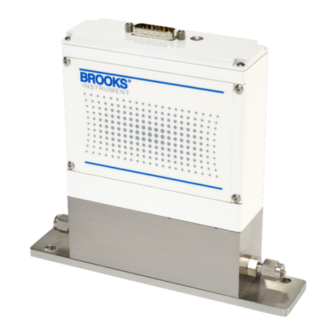
2.5mm DIAGNOSTIC PORT
DSUB 15 PIN
ZERO BUTTON
ACCESS PORT
LED STATUS LIGHT
Step 3: Electrical Connections
NEMA 1 / IP40 Meter/Controller
D-Connector Functions Legends:
• = Feature Available
N/A = Not Available
NOTE: Chassis ground is available through the D-Connector back
shell.
D-Connector for QmC NEMA 1 / IP40
Pin Out Connections
3-A1
3-A2
Pin Function Controller Meter
1 Setpoint Common * N/A
2 0-5(10) Volt Flow Output * *
3 (TTL) Open Collector Alarm Output * *
4 (0)4-20 mA Flow Output * *
5 Power Supply (14-27 V) * *
6 Not Connected N/A N/A
7 (0)4-20 mA Setpoint Input * N/A
8 0-5(10) Volt Setpoint Input * N/A
9 Power Common * *
10 Signal Out Common * *
11 Not Connected N/A N/A
12 ValveOverrideInput * N/A
13 Density or Tempertaure output,
Current or Voltage
* *
14 RS-485, B(-) Input/Output * *
15 RS-485, A(+) Input/Output * *
Receipt of Equipment
Whentheequipmentisreceived,theoutsidepackingcaseshould
be checked for damage incurred during shipment. If the packing
caseisdamaged,thelocalcarriershouldbenotiedatonce
regarding his liability. A report should be submitted to the nearest
BrooksInstrumentlocationlistedontheGlobalServiceNetwork
page on our website: brooksinstrument.com/service-support
Removetheenvelopecontainingthepackinglist.Carefullyremove
the instrument from the packing case. Make sure spare parts are
not discarded with the packing materials. Inspect for damaged or
missing parts.
Return Shipment
Priortoreturninganyinstrumenttothefactoryforanyreason,visit
our website for instructions on how to obtain a Return Materials
Authorization Number (RMA #) and complete a Decontamination
Statement to accompany it: brooksinstrument.com/service-support
All instruments returned to Brooks also require a Material Safety
DataSheet(MSDS)fortheuid(s)usedintheinstrument.Failure
toprovidethisinformationwilldelayprocessingoftheinstrument.
Instrumentmusthavebeenpurgedinaccordancewiththe
following:
Equipment Receipt and Return Procedures
Aftertheowmeterorowcontrollerhasbeeninstalledinthe
system it is ready for operation.
Meter: Themeterwillprovideaowsignalproportionaltothe
fullscaleowofthedeviceasindicatedonthedevicelabel.
Controller: Youmustprovideasetpoint/commandsignaltothe
controller. The controller will read the setpoint signal and will
automaticallyadjustthevalvetotheappropriatepositionto
achievethedesiredowandwillprovideaowsignal
proportionaltothefullscaleowofthedeviceasindicatedon
thedevicelabel.
Step 4: Zeroing Procedure
To assure measurement accuracy, the instrument must be
zeroed to the operational installation conditions:
• Apply power to instrument for approximately 45 minutes to
reachastablethermalconditionpriortoapplyingow.
• Flowtheprocessuidintotheinstrumentandallowsucient
time for the sensor to reach normal operating temperature.
• Closetheshutovalvedownstreamtoeliminateanypressure
dierentialacrosstheinstrument.
• AfterconrmingaNOowcondition,pressthezeroingbutton
for at least 3 seconds
• Zeroing button is located on the side of the instrument’s
housing.
• The zeroing process takes approximately 60 seconds. Status
lightwillashred.
• A solid Green LED means a successful zero.
• A solid Red LED means an unsuccessful zero.
Note: If solid Red LED is indicated, recycle power and repeat
zeroingprocedureorcontactTechnicalServicesatBrooks
Instrument
Step 5: Operation

