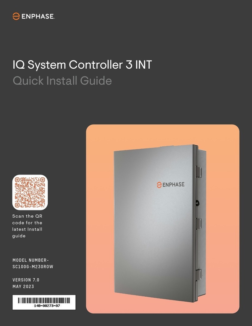
enphase E3 PCBA User manual

QUICK INSTALL GUIDE
Replacing the E3 PCBA from the IQ System
To replace IQ System Controller, read and follow all warnings and instructions in this guide. Safety warnings are listed on the back of this guide. These instruc-
tions are not meant to be a complete explanation of how to design and install an energy storage system.
All installations must comply with national and local electrical codes and standards. Only qualied electricians shall install, troubleshoot, or replace the IQ Sys-
tem Controller.
All service or maintenance operations on the IQ System Controller unit should be performed only by trained and qualied personnel who understands and fol-
lows the required safety codes and use adequate Personal Protective Equipment (PPE).
* WARNING! The following procedure is to be performed only when the grid is functional and the Enphase system has not formed a microgrid.
* WARNING! Failure to follow this warning could cause personal injury or death. Before performing service or maintenance operations on unit, always turn off
main power switch to unit and install lockout tag. Unit may have more than one power switch.
© 2021 Enphase Energy. All rights reserved. Enphase, the Enphase logo, IQ System Controller, IQ Battery, IQ Gateway, IQ combiner, IQ microinverter, Enphase App
and other trademarks or service names are the trademarks of Enphase Energy, Inc. Data subject to change. Rev01-10-23-2021
Tools and parts to be used:
Open the IQ System Controller and remove the Dead-
front
A ) Open the three latches that lock the enclosure door. To release the
latch, pull the latch handle forward and then to the right. With all the
latches opened, swing open the enclosure door.
B ) Use a Phillips Size #2 screw driver to loosen the six screws along the
periphery of the deadfront. Support the deadfront to keep it from falling
while performing the next step.
C ) While supporting the deadfront, use a blade screwdriver to disconnect
the deadfront ground wire from the grounding bar before removing the
deadfront.
D ) Use the two tabs on the front to assist handling the deadfront during
dismantling.
E ) Remove deadfront from the IQ System Controller unit and place it aside
safely.
2
Open the Controller PCBA Cover
A ) Locate the Zigbee antenna cable zip tied to right side of the E3 cover
(metal cover) as shown in Figure 1. Using the small wire cutter cut the
zip-tie tied between E3 Cover and Zigbee antenna cable.
NOTE:
1. Mark the zip tie location on antenna cable using a sharpie for easy
locating while reinstalling zip-tie.
2. Pay attention to only cut zip tie, do not cut or damage the antenna
cable or the EMI sheet wrapped around the cable.
3
B ) Unscrew the 4 screws on top of E3 cover. Do not remove the ground
(green) cable (indicated in Figure 2a) connected on the left side of E3
cover. Remove and secure the E3 cover on left side empty space as
shown in Figure 2b.
NOTE: Do not disconnect ground wire connection to E3 cover.
S.No Component Qty Source of part
1E3 replacement PCB 1 Provided in kit
2Zip tie 2 Provided in kit
3 Serial number label- for E3 1 Provided in kit
4 Serial number label- for IQ System
Controller
1 Provided in kit
5 Spare Zigbee antenna assembly 1 Provided in kit
6Philips Screwdriver (Size #2) 1 Arranged by installer
7Flat head Screwdriver (any size) 1 Arranged by installer
8 Multimeter 1 Arranged by installer
9 Sharpie 1 Arranged by installer
10 Wire cutter 2 Arranged by installer
11 Step Ladder 1 Arranged by installer
12 ESD Protective hand gloves 1 pair Arranged by installer
PROCEDURE
Figure 2a: E3 cover with ground
wire indicated
Figure 2b: E3 cover after being
removed
Figure 1: Zigbee Antenna tied to the side of the E3 cover
De-energizing the IQ System Controller
A ) Turn DC switches in IQ Batteries to OFF. ( For instruction on opening IQ
Battery cover please refer to the following document https://enphase.
com/sites/default/les/2021-04/IQ Battery3-10-QIG-EN-US.pdf).
B ) Open IQ Battery breaker in IQ System Controller.
C ) Open PV breaker in IQ System Controller.
D ) Open the mains breaker.
E ) Disconnect the grid source power supply (breaker in main panel).
F ) Open generator breaker.
G ) Use multi meter to measure AC voltage on all the following terminals –
PV, IQ Battery, Grid , Load and Generator. It is safe to work on IQ System
Controller only when no voltage is detected on any of these terminals
and you have ensured that all IQ Battery units have DC powered off.
1

L ) Place the cover in the right position while being careful to route the
Zigbee cable wire through the conduit provided in the cover.
M ) Loosely install all 4 screws on E3 cover and then go back over them
and tighten fully. The torque rating for the 4 screws is 1 N.m (8.8 lb.in).
N ) Install the dead front carefully without causing any push/damage to
antenna cable as shown in Figure 5.
Replace the Controller PCBA and Cover
A ) Remove the new PCBA from its packaging.
B ) Insert the new cable tie on the new board in the cable tie slot provided
in the board, this will be used to route the Zigbee antenna cable.
C ) If the insulator was removed, retrieve the insulator and align it with the
new PCBA so that the insulator is on the bottom and the screw holes
on both insulator and PCBA are aligned.
D ) Place the assembled PCBA and insulator in position, align the screw
holes on the IQ System Controller.
E ) Loosely screw the board with 5 screws with Torq screwdriver, T10.
Leave the screws loose until the ziptie is tightened.
F ) Reconnect the white connector to the E3 board.
G ) Reconnect the Zigbee antenna, and route the cable through the zip
tie which had been attached to E3 board in step B. Be sure to insert
antenna onto chip in top right corner. The lower chip does not receive
an antenna. Trim the zip tie once the antenna is routed.
H ) Reconnect the red connector to the E3 board
I ) Using a hand screw driver , nish tightening the T10 Torq screws to
attach the board. Do not use a power tool as this can damage the
board. The approximate Torque needed is 0.7 N.m (6.2 lb.in).
J ) Insert another cable tie through the hole on the right side of the E3
cover.
K ) Secure the Zigbee antenna cable to the E3 cover as shown in Figure 4.
5
Figure 4: Zip tie pulled through E3 Cover
Figure 5: Antenna cable position in IQ System Controller
Remove the E3 PCBA and Insulator
A ) Make sure to wear ESD protection gloves before handling the connec-
tors on E3 board.
B ) Ensure the following steps are performed 120 seconds after the IQ
System Controller has been powered off.
C ) Cut the zip tie on E3 board with the cutter (Zip tie location indicated in
Figure 3).
D ) Disconnect the red connector from E3 board (indicated in Figure 3) .
E ) Disconnect the Zigbee antenna (indicated in Figure 3).
F ) Disconnect the white connector from E3 board (Indicated in Figure 3)
G ) Unscrew the 5 screws with Torx screwdriver T10 (Indicated in Figure 3
with red circles).
H ) Remove the E3 controller PCBA. If the insulator below the PCBA does
not stay in place, remove the insulator and keep it handy as it will have
to be reinstalled while installing the new PCBA.
4
Figure 3: Connections and screws on E3 board
Steps to be followed in case of damage to zigbee
antena
A ) Take a new fresh antenna which is provided in E3 replacement kit.
B ) Position the new antenna beside the present antenna as shown below
and paste the adhesive tape as shown in Figure 6.
C ) Remove the adhesive tape holding the existing antenna as shown in
Figure 7.
D ) Follow the steps from section 5 ( Replace the Controller PCBA and
Cover) .
6
Figure 6: Pasting new Zigbee antenna adjacent to existing one
Figure 7: Removing damaged Zigbee antenna
Zigbee antenna
Zip tie
Red connector
White connector

C ) Before energizing the IQ System Controller check the Manual
override position. Toggle the manual override to the “RIGHT”/ OFF
position. If the manual override switch had not been engaged (it
is already in the “RIGHT”/ OFF position, do not disturb the manual
override toggle) replace cover and sticker if available.
D ) Do not Turn on the DC switch on the IQ Battery
E ) You must ensure that all electrical circuits external to IQ System
Controller are completed and safe before energizing IQ System
Controller in the following order:
• NFT breaker
• Main breaker
• PV breaker
• IQ Battery breaker
• Generator breaker
• Load breaker
F ) After IQ Battery breaker is turned ON wait and observe if the IQ
Battery red LEDs ash 3 times continuously. Wait for 90 seconds,
with the red LED ashing , before turning on the DC switch on IQ
Battery.
G ) The IQ Battery LED should change to blue or green based on SOC of
battery.
H ) For closing the cover of the IQ Battery please refer to the IQ Battery
QIG (https://enphase.com/sites/default/les/2021-04/IQ Battery3-
10-QIG-EN-US.pdf).
I ) Energize the circuit feeding the IQ System Controller. If installed, turn
the breaker feeding the IQ System Controller to ON position.
H ) Close and secure the door of the IQ System Controller.
I ) The E3 PCBA replacement kit comes with stickers which will have
new serial numbers for the IQ System Controller. Please remove the
older serial numbers and paste the new ones in its place.
A ) Reconnect the deadfront ground cable to the grounding bar, torque
as shown in Table 1.
B ) Replace the dead front using the six captive screws. Tighten the
cover screws using a PH#2 screw driver. The torque for the screws
are 1.2 Nm (10.6 lb.in).
Close and Energize IQ System Controller
7
Table 1: Torque value for Neutral and ground bar
Neutral and Ground bars Torque (N.m / lb.in)
Large holes (5/16 -24 UNF) 5.6/50
5.1/45
4.5 /40
4.0/35
Small Holes (10-32UNF) 2.8 /25
1.7 /15
A ) In order to compelte the E3 PCBA replacement the IQ System
Controller needs to be retired and the new IQ System Controller
serial number needs to be registered using Enphase Installer App.
B ) In order to do this please refer to the Technical Brief for Enphase
Energy System Commissioning using Enphase Installer App 3.0. It
can be found in this link: https://support.enphase.com/s/article/IQ
System Controller-RMA-Instructions.
Steps for Retiring the IQ System Controller and reg-
istering the new IQ System Controller in Enphase Installer
App
8

Enphase Customer Support: enphase.com/en-us/support/contact
Safety and Advisory Symbols
+DANGER: This indicates a hazardous situation, which if not avoided, will
result in death or serious injury.
*WARNING: This indicates a situation where failure to follow instructions
may be a safety hazard or cause equipment malfunction. Use extreme
caution and follow instructions carefully.
✓NOTE: This indicates information particularly important for optimal system
operation. Follow instructions carefully.
Safety Instructions
+DANGER: Risk of electric shock. Risk of re. Only qualied electricians should
install, troubleshoot, or replace the IQ System Controller.
+DANGER: Risk of electric shock. Risk of re. Do not attempt to repair the
IQ System Controller. Tampering with or opening the IQ System Controller
will void the warranty. If the IQ System Controller fails, contact Enphase
Customer Support for assistance at enphase.com/en-us/support/contact.
+DANGER: Risk of electric shock. Do not use Enphase equipment in a manner
not specied by the manufacturer. Doing so may cause death or injury to
persons, or damage to equipment.
+DANGER: Risk of electric shock. Do not install the IQ System Controller
without rst removing AC power from the photovoltaic system and ensuring
that the DC switch on the Enphase IQ Batteries are off. Disconnect the power
coming from the photovoltaics and ensure that the DC switch on the IQ
Batteries are off before servicing or installing.
+DANGER: Risk of electric shock. Risk of re. Do not work alone. Someone
should be in the range of your voice or close enough to come to your aid
when you work with or near electrical equipment.
+DANGER: Risk of re. Do not allow or place ammable, sparking, or explosive
items near the IQ System Controller.
+DANGER: Risk of electric shock. In areas where ooding is possible, install
the IQ System Controller at a height that prevents water ingress.
*WARNING: Risk of equipment damage. IQ System Controller is shipped and
stored on its back. The upright position is only needed when installed.
*WARNING: You must install the IQ System Controller only on a suitable wall
using an Enphase wall-mount bracket.
*WARNING: Before installing or using the IQ System Controller, read all
instructions and cautionary markings in this guide and on the equipment.
*WARNING: Do not install or use the IQ System Controller if it has been
damaged in any way.
*WARNING: Do not sit on, step on, place objects on, or insert objects into the
IQ System Controller.
*WARNING: Do not place beverages or liquid containers on top of the IQ
System Controller. Do not expose the IQ System Controller to ooding.
✓NOTE: Perform installation and wiring, including protection against lightning
and resulting voltage surge, in accordance with all applicable local electrical
codes and standards.
✓NOTE: Because IQ Battery is grid forming, you must install signage in accord-
ance with NEC articles 705, 706, and 710.
✓NOTE: Using unapproved attachments or accessories could result in dam-
age or injury.
✓NOTE: Install properly rated over current protection as part of the system
installation.
✓NOTE: To ensure optimal reliability and to meet warranty requirements,
the IQ System Controller must be installed and/or stored according to the
instructions in this guide.
✓NOTE: The IQ System Controller is compatible only with the IQ Gateway
or Envoy S-metered communications gateway properly tted with USB
hub, USB radios, and production and Consumption/PCS CTs. The Envoy is
required for operation of the IQ System Controller. Earlier versions of the
Enphase Envoy communications gateway are incompatible.
✓NOTE: The Enphase IQ System Controller is intended to operate with an Inter-
net connection through the Envoy. Failure to maintain an Internet connection
may have an impact on the warranty. See Limited Warranty for full terms and
services (enphase.com/warranty).
✓NOTE: When replacing an Enphase IQ System Controller, you must replace
it with an IQ System Controller of the same type, with the same AC current
rating.
✓NOTE: Properly mount the IQ System Controller. Ensure that the mounting lo-
cation is structurally suited to bearing the weight of the IQ System Controller.
✓NOTE: During use, storage, and transport, keep the IQ System Controller:
• Properly ventilated
• Away from water, other liquids, heat, sparks, and direct sunlight
• Away from excessive dust, corrosive and explosive gases, and oil smoke
• Away from direct exposure to gas exhaust, such as from motor vehicles
• Away from falling or moving objects, including motor vehicles. If mounted
in the path of a motor vehicle, we recommend a 91cm (36-inch) minimum
mounting height.
• In a location compliant with re safety regulations
• In a location compliant with local building codes and standards
✓NOTE: IQ System Controller is not suitable for use as service equipment
in Canada.
SAFETY
IMPORTANT SAFETY INSTRUCTIONS. SAVE THESE INSTRUCTIONS. This guide contains important instructions that you must follow during installation
and maintenance of the Enphase IQ System Controller. Failing to follow any of these instructions may void the warranty (enphase.com/warranty).
In Case of Fire or Other Emergency
In all cases:
• If safe to do so, switch off the AC breaker for the IQ System Controller circuit,
and if an isolator switch is present, switch off the AC isolator for the IQ
System Controller circuit.
• Contact the re department or other required emergency response team.
• Evacuate the area.
In case of re:
• When safe, use a re extinguisher. Suitable types are A, B, and C dry chemical
re extinguishers. Additional extinguishing media include carbon dioxide, or
alcohol-resistant foams.
In case of ooding:
• Stay out of water if any part of the IQ System Controller or wiring is
submerged.
• If possible, protect the system by nding and stopping the source of the
water, and pumping it away.
• If water has contacted the UNIT, call your installer to arrange a inspection.
If you are sure that water has never contacted the battery, let the area dry
completely before use.
In case of unusual noise, smell or smoke:
• Ensure nothing is in contact with the IQ System Controller or in the venting
area on top of the IQ System Controller.
Safety Instructions, continued
Environmental Protection
ELECTRONIC DEVICE: DO NOT THROW AWAY. Waste elec-
trical products should not be disposed of with household
waste. Refer to your local codes for disposal requirements.
Other enphase Controllers manuals
