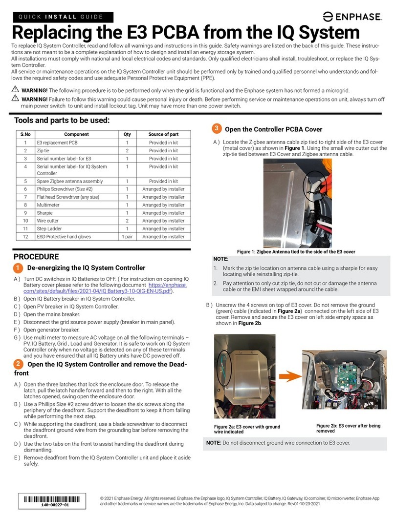
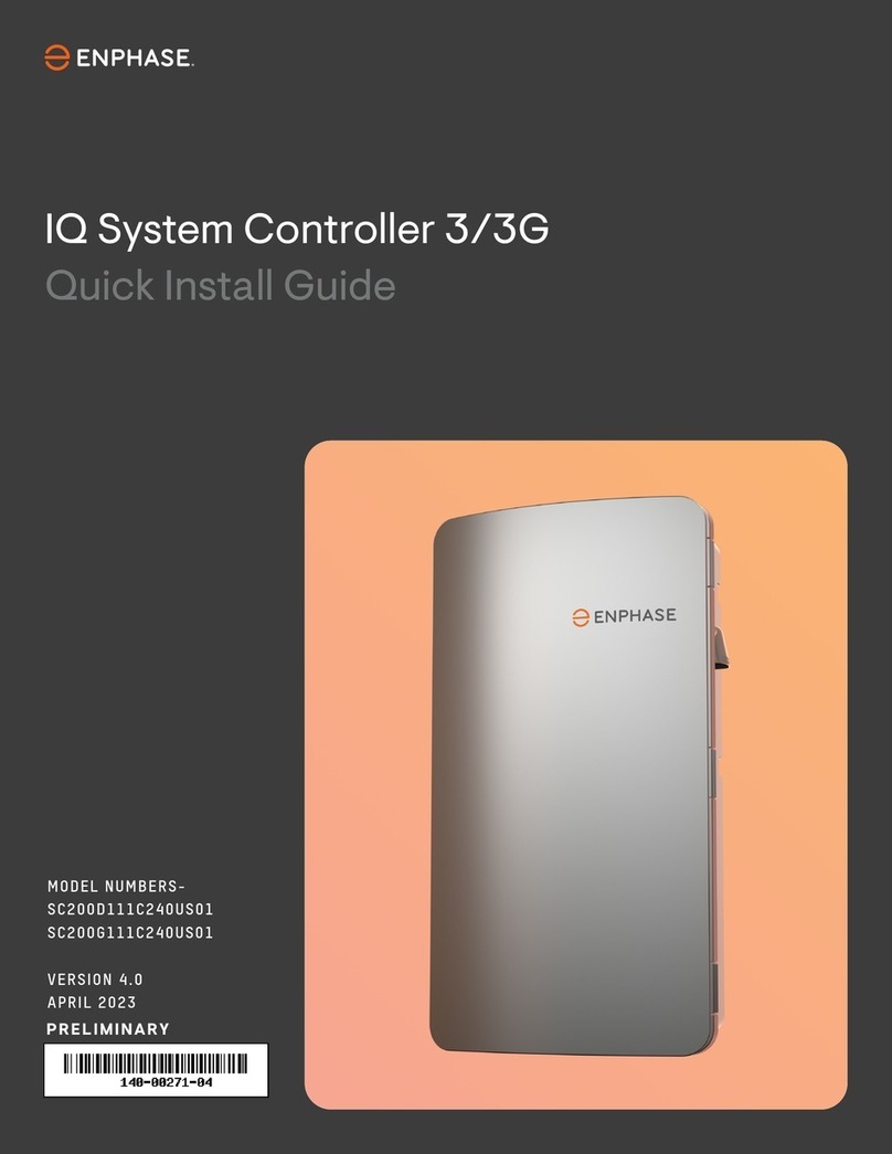
enphase IQ System Controller 2 User manual

2
IQ System Controller 2 Quick Install Guide
The IQ System Controller 2 connects the home to grid power,
the IQ Battery storage system, and solar PV. It provides microgrid
interconnection device (MID) functionality by automatically
detecting and seamlessly transitioning the home energy system
from grid power to backup power in the event of a grid failure.
It consolidates all interconnection equipment into a single enclosure
and streamlines grid-independent capabilities of PV and storage
installations by providing a consistent, pre-wired solution for
residential microgrid applications. It integrates a microgrid
interconnect device (MID), a neutral-forming autotransformer (NFT)
and supports lugs to connect solar PV, batteries, and third-party
generators.
The IQ System Controller 2 supports IQ8, IQ7, or M Series
Microinverters.
To install the IQ System Controller 2, read and follow all
warnings and instructions in this guide and documents at
https://support.enphase.com.
To access the latest technical brief and user guides for generator
integration, see the Generator Support page at https://enphase.
com/installers/storage/generator.
Safety warnings are listed at the end of this guide. These instructions
are not meant to be a complete explanation of how to design and
install an energy storage system. All installations must comply with
national and local electrical codes and standards. Only qualied
electricians shall install, troubleshoot, or replace the IQ System
Controller 2.

3
IQ System Controller 2 Quick Install Guide
Table of contents
Scenario 1
Full Energy Independence conguration
Whole Home backup
Scenario 2
Home Essentials Backup conguration
Partial Home backup
Scenario 3
Home Essentials Backup conguration
Sunlight Backup with generator
What’s in the box
Tools/additional items required
Section A
Mounting the product
Plan a location for the IQ System Controller 2
Step 1: Minimum clearance
Step 2: Install the mounting bracket
Step 3: Open the dead front
Section B
Mounting the breakers
Internal view of IQ System Controller 2
Wiring for service entrance
Install main and backup breakers
Breakers for IQ8 Systems without generator
Breakers for IQ8 Systems with generator
Breakers for non IQ8 Systems
Section C
Wiring
Drill conduits
DER wiring
Aux wiring: System Shutdown Switch
Aux wiring: IQ Load Controller
Aux wiring: Generator control
Main/supply side wiring
Backup loads wiring
CT wiring
Close and energize IQ System Controller 2
Safety

4
IQ System Controller 2 Quick Install Guide
This gure shows the system conguration. For wiring
details, see the “wiring” section.
Scenario 1
Whole home backup with
IQ System Controller 2
This is the preferred conguration for the back up of the entire main
load panel. This conguration supports up to an 80 A breaker each for
the PV and IQ Battery, and the generator (optional).
The microinverter ranges supported in this conguration are IQ8, IQ6,
IQ7, M215, and M250 Series.
Note: The System Shutdown Switch is not used for IQ6, IQ7, and M Series
systems. Refer to the System Shutdown wiring section for details.
Additional wiring and components are required when integrating generators.
Refer to the Generator integration page for technical briefs and guides
https://enphase.com/installers/storage/generator.

5
IQ System Controller 2 Quick Install Guide
This gure shows the system conguration. For wiring
details, see the “wiring” section.
Scenario 2
Partial home backup with
IQ System Controller 2
This is the preferred conguration for partial home backup with PV
and IQ Batteries. The generator can be integrated with IQ System
Controller 2 based on the homeowner’s needs.
The microinverter ranges supported in this conguration are IQ8,
IQ6, IQ7, M215, and M250 Series.
Note: The System Shutdown Switch is not used for IQ6, IQ7, and M Series
systems. Refer to the System Shutdown wiring section for details.
Additional wiring and components are required when integrating generators.
Refer to the Generator integration page for technical briefs and guides
https://enphase.com/installers/storage/generator.

6
IQ System Controller 2 Quick Install Guide
Partial Home backup with
Sunlight Backup and generator
This is the preferred conguration for partial home backup using
only IQ8 PV i.e., Sunlight Backup. The generator or IQ Battery can be
integrated with IQ System Controller 2 based on the homeowner’s
needs.
It is recommended that installers use two IQ Load Controllers for
load shedding to ensure seamless back up of essential loads using
IQ8 Microinverters. At least one IQ Load Controller is required to
successfully commission a Sunlight Backup system.
Do not install a Sunlight Backup system for a whole home backup
scenario. This conguration can only be supported with IQ8
Microinverters.
Note: The System Shutdown Switch is not used for IQ6, IQ7, and M Series
systems. Refer to the System Shutdown wiring section for details.
Additional wiring and components are required when integrating generators.
Refer to the Generator integration page for technical briefs and guides
https://enphase.com/installers/storage/generator.
Scenario 3
This gure shows the system conguration. For wiring
details, see the “wiring” section.

7
IQ System Controller 2 Quick Install Guide
What’s in the box
IQ System Controller 2 Wall-mounting bracket System Shutdown Switch
Accessory kit
ITEM NAME ITEM CATEGORY DESCRIPTION QUANTITY
Filler Cover Mounting BKT-L 200G Enpower Plastic part Filler Cover Mounting BKT-L 200G 2
Filler Cover Mounting BKT-R 200G Enpower Plastic part Filler Cover Mounting BKT-R 200G 2
Screw, Pan Hd, Phillips #3, M6 x 25 mm Lg
(5 mm Shank - 20 mm Thread), Machine, 304 SS Fastener Screw, Pan Hd, Phillips #3, M6 x 25 mm Lg (5 mm
Shank - 20 mm Thread), Machine, 304 SS 2
Screw, pan Hd, Torx X20, Machine,
#8-32 UNC, 0.63" Lg, A2-70 Fastener Screw, pan Hd, Torx X20, Machine, #8-32 UNC, 0.63" Lg,
A2-70 1
Lit Kit Label, Enpower 200G Label Lit Kit Label, IQ System Controller 200G 1
Label, Enpower, CT Field Label 6
Label, Enpower, PCS Field Label 2
Feed-through header with Cable Assy Header
Enpower 200G R2 Cable assembly Cable Assy Header IQ System Controller 200G R2 4
NEC Labels for Rapid Shutdown Label Labels required as per NEC for rapid shutdown switch 2
MODEL NUMBER DESCRIPTION
EP200G101-M240US01
NOTE: No longer sold separately.
IQ System Controller 2 with neutral-forming transformer (NFT) and microgrid
interconnect device (MID). Streamlines grid-independent capabilities of PV and
storage installations.
EP200G-SC2-RSD-KIT Includes EP200G101-M240US01, System Shutdown Switch (EP200G-NA-02-RSD) with
red, black, orange and purple 12 AWG wires, and breaker for powering IQ Gateway.
EP200G-SC2-RSD-BRK-KIT
Includes EP200G-SC2-RSD-KIT, three Eaton BR220B breakers for either IQ System
Controller 2 or IQ Combiner, two BR240B breakers and one BR260 breaker for
IQ System Controller 2, two X-IQ-NA-HD-125A hold-down kits for IQ Combiner, and
two EP200G-NA-HD-200A hold-down kits for IQ System Controller 2.
Comes pre-wired with 4 x 20 ft.
color-coded wires.

8
IQ System Controller 2 Quick Install Guide
Tools/additional
items required
S. NO ITEM NAME QUANTITY SOURCE
1 CT-200-SPLIT 2 IQ Combiner/Enphase Store
2 EP200G-HNDL-R1 (lifting handle) 1 Enphase Store
3 Breakers, dierent ratings 4 Enphase Store/retail outlets*
4 Conduits (with ttings and tting tools) As required Provided by installer
5 Drill 1 Provided by installer
6 5/32" pilot bit 1 Provided by installer
7 Screwdriver 1 Provided by installer
8 Wrench 1 Provided by installer
9 Adjustable wrench 1 Provided by installer
10 Torque wrench 1 Provided by installer
11 Level 1 Provided by installer
12 5/32" Allen key 1 Provided by installer
13 Conductor stripper 1 Provided by installer
14 Electrician’s hole saw (2") or punch set 1 Provided by installer
15 Stud nder (if required) 1 Provided by installer
16 Conduit ground hub rings 1 Provided by installer
17 #10, 1/4" or 5/16" lag bolts or screw 3" long (depending
on attaching wall) - for each wall-mount bracket 3 Provided by installer
*2 Eaton BR240B, 1 Eaton BR260, and 3 Eaton BR220 included with EP200G-SC2-RSD-BRK-KIT.

9
IQ System Controller 2 Quick Install Guide
Plan a location for the
IQ System Controller 2
Mounting the product
Section A
• IQ System Controller 2 is NEMA type 3R rated and can be mounted both
indoors and outdoors. Install the unit where it is not exposed to direct rainfall.
• Install this product where cables from PV/IQ Combiner, grid, and IQ Battery
are easily accessible and can be terminated at the IQ System Controller 2.
• This product is designed to be installed on a vertical wall only.
Do not install this product at on the ground.
• The mounting surface must support 87 lbs.
• Follow all local standards and regulations during installation.
• The product operates within an ambient temperature range from -40°C to 50°C.
• Do not install this product in a place directly exposed to sunlight.
• Do not install the product in a dusty environment.
• This product must not be installed at altitudes above 8,200 ft (2,500 m).
• In ood-prone areas, ensure that the clearance from the ground is sucient
to avoid water ingress.
-40°C
+50°C

10
IQ System Controller 2 Quick Install Guide
19.7 in
36 in
9.7 in
6 in
35 in
36 in
6 in
6 in
This product must be installed with clearance at the left, right, top,
bottom, and front of the product as shown in the gure.
Follow all local standards and regulations related to the mounting of
an IQ System Controller 2.
Section A - Mounting the product
Step 1:
Minimum clearance

11
IQ System Controller 2 Quick Install Guide
6
Step 2:
Install the mounting bracket
Install the mounting bracket and mount the IQ System Controller 2
as per the following instructions:
• The IQ System Controller 2 weighs 39.4 kg (87 lbs) and will
require two people to lift the unit.
• Risk of injury and equipment damage. Avoid dropping the
IQ System Controller 2. Doing so may create a hazard, cause
serious injury, and/or damage the equipment.
Provided in the accessory kit
21
4
3
5
• Risk of injury and equipment damage. Do not release the
IQ System Controller 2 until you ensure that the IQ System
Controller 2 is fully seated on the wall-mount bracket shelf.
• Use 3" long wood screw #10, 1/4", or 5/16" (depending on
the attachment wall) or masonry attachments if installed in
masonry to attach the IQ System Controller 2 bracket. Use one
screw and washer for each slot. The slot size of the IQ System
Controller 2 wall-mount bracket is 8.5 mm.
• Check the local standards with a structural engineer for local
requirements. Washers should be used between fastener heads
and wall-mount bracket.
Section A - Mounting the product

12
IQ System Controller 2 Quick Install Guide
Step 3:
Open the dead front
Before removing the dead front, ensure the IQ System Controller 2
is completely de-energized.
Risk of equipment damage. Do not wire the IQ System
Controller 2 when it is energized.
• Risk of equipment damage. Do not remove the pre-installed
solar shield attached to the enclosure door.
• Risk of electric shock. Do not modify the dead front other than
to remove or replace ller plates, as needed. The product
warranty can be aected in case of modication.
The ground connection to the dead front needs to
be carefully disconnected before the dead front can
be dismantled from the IQ System Controller 2.
Philips screw #2
Section A - Mounting the product
1
2 3

13
IQ System Controller 2 Quick Install Guide
Main lugs
Neutral terminals
Ground terminals
Load center for
DER breakers
Backup lugs
AUX and System
Shutdown terminals
Terminals for
DER cables
Internal view of
IQ System Controller 2
The following gure shows the IQ System Controller 2 after the
dead front is removed. It comes with an inbuilt neutral forming
transformer, microgrid interconnection device, automatic transfer
switch, and a panel board to mount plug-in type breakers.
Section B
Mounting the breakers

14
IQ System Controller 2 Quick Install Guide
If the IQ System Controller 2 is used as service entrance
equipment:
• Do not remove the green-colored system bonding jumper
• Paste labels provided in the accessory kit
If the IQ System Controller 2 is NOT used as service entrance
equipment:
• Remove the system bonding jumper wire
Grounding Electrode Terminal
Grounding Electrode Terminal
Label
Label
Main/Service Disconnect
Suitable for use as Service Equipment
Main/Service Disconnect
Suitable for use as Service Equipment
Wiring for service entrance
Section B - Mounting the breakers
Magnied view
Magnied view

15
IQ System Controller 2 Quick Install Guide
Install main and backup
breakers
If breakers are being installed for main and backup connections,
the lugs should be removed, and the breakers should be installed.
Only Eaton CSR range breakers with ratings between 100A-200A
can be used for a main and backup connection.
Risk of equipment damage. Do not wire the IQ System
Controller when it is energized.
Backup connection Main connection
Screw part of
Eaton breaker kit
Screw part of
Eaton breaker kit
Torx - T20
13.3 lb.in
Torx - T20
13.3 lb.in
3/8 in
35.4 lb.in
Hex nut from lugs
to be reused for
breakers
3/8 in
35.4 lb.in
Hex nut from
lugs to be
reused for
breakers
Section B - Mounting the breakers
ENPHASE BREAKER SKU EATON BREAKER PART
BRK-100A-2P-240V CSR2100N
BRK-125A-2P-240V CSR2125N
BRK-150A-2P-240V CSR2150N
BRK-175A-2P-240V CSR2175N
BRK-200A-2P-240V CSR2200N

16
IQ System Controller 2 Quick Install Guide
The IQ System Controller 2 comes pre-installed with a 40 A breaker
for the neutral forming transformer (NFT). When a generator is not
installed, the NFT breaker should not be removed.
Breakers for IQ8 Systems
without generator
NFT breaker
Pre-installed in factory,
not to be disturbed
IQ Gateway breaker
Wire IQ Gateway in IQ Combiner
to factory-installed breaker in
IQ System Controller 2
Solar branch circuit
breakers
Use hold-down kits
(X-IQ-NA-HD-125A)
with included 20 A
breakers. Each branch
circuit requires a
separate breaker.
Hold-down kit
(X-IQ-NA-HD-125A)
Wiring to power IQ Gateway
Solar breaker
Use hold-down kit
(EP200G-NA-HD-200A)
with included breakers
(20 A/40 A/60 A) or a
correctly sized breaker
Pre-wired red and
black wires
Connect to storage and
solar breakers
Storage breaker
Use hold-down kit
(EP200G-NA-HD-200A)
with included breakers
(20 A/40 A/60 A) or a
correctly sized breaker
ENPHASE BREAKER PART EATON BREAKER PART TORQUE
BRK-20A-2P-240V-B BR220B
27 lb.in
BRK-40A-2P-240V-B BR240B
BRK-60A-2P-240V BR260
BRK-80A-2P-240V BR280
Section B - Mounting the breakers

17
IQ System Controller 2 Quick Install Guide
IQ System Controller 2 allows for generator integration with the
Enphase Energy Systems. The breaker on the bottom right slot
of the panel board can be sized and used to integrate the generator.
For generator control and power line schematics, refer to the
generator control section.
Breakers for IQ8 Systems
with generator
NFT and IQ Gateway breaker
Remove the factory-installed
NFT breaker and install a
Quad breaker (Eaton Part:
BQC220240) Wire as shown
alongside
Generator breaker
Use hold-down kits
(EP200G-NA-HD-200A)
with included breakers or
a correctly sized breaker
Solar breaker
Use hold-down kit
(EP200G-NA-HD-200A)
with included breakers
(20 A/40 A/60 A) or a
correctly sized breaker
Storage breaker
Use hold-down kit
(EP200G-NA-HD-200A)
with included breakers
(20 A/40 A/60 A) or a
correctly sized breaker
ENPHASE BREAKER PART EATON BREAKER PART TORQUE ON WIRE
BRK-20A-2P-240V-B BR220B
27 lb.in
BRK-40A-2P-240V-B BR240B
BRK-60A-2P-240V BR260
BRK-80A-2P-240V BR280
BRK-20A40A-4P-240V BQC220240
Pre-wired red and
black wires
Connect to storage and
solar breakers
Pre-wired red and
black wires
Connect to generator
breaker
Section B - Mounting the breakers
L1 - IQ Gateway
L1 - NFT
L2 - NFT
L2 - IQ Gateway
NOTE:
A cable used to connect IQ Gateway power terminals to the
quad breaker must adhere to local electrical codes.

18
IQ System Controller 2 Quick Install Guide
Breakers for non IQ8 Systems
The IQ System Controller 2 comes pre-installed with a 40 A breaker
for the neutral forming transformer (NFT). When a generator is not
installed, the NFT breaker should not be removed.
Section B - Mounting the breakers
*For generator integration, follow the same instructions applicable for IQ8 Systems.
ENPHASE BREAKER PART EATON BREAKER PART TORQUE ON WIRE
BRK-20A-2P-240V-B BR220B
27 lb.in
BRK-40A-2P-240V-B BR240B
BRK-60A-2P-240V BR260
BRK-80A-2P-240V BR280
BRK-20A40A-4P-240V BQC220240
NFT breaker
Pre-installed in the factory,
not to be disturbed
IQ Gateway breaker
Remove breaker from
IQ System Controller 2
and wire IQ Gateway to the
breaker in IQ Combiner*
Solar breaker
Use included breakers
(20 A/40 A/60 A) or a
correctly sized breaker
Pre-wired red and
black wires
Connect to storage and
solar breakers
Storage breaker
Use included breakers
(20 A/40 A/60 A) or a
correctly sized breaker

19
IQ System Controller 2 Quick Install Guide
Section C
Wiring
Drill conduits
Drill the conduit entry holes as needed and install conduit grounding
lugs for each opening. Be sure to reseal unused conduit entry holes
with sealing plugs.
Main supply conductors may enter the IQ System Controller 2 from
the bottom or the bottom-left side.
Backup load conductors may enter the IQ System Controller 2 from
the bottom or bottom-right side.
IQ Battery, IQ Combiner, and generator conductors may enter from
the bottom, bottom-left or bottom-right sides.
Size the conductors (line, neutral, and ground) depending on the
service or breaker rating and voltage rise requirements according
to local codes.
Refer to the conductor rating table on the door of the IQ System
Controller 2.
CONDUIT LOCATION MAIN BACKUP LOADS DER
Bottom
Left wall
Right wall

20
IQ System Controller 2 Quick Install Guide
AWG TORQUE (LB.IN)
14-10 25
8 30
4-6 35
2-3 40
IQ Battery wiring Generator wiringPV wiring
1/8"2-14 AWG
DER wiring
Section C - Wiring
NEUTRAL AND GROUND CONNECTIONS AWG TORQUE (LB.IN)
Neutral and ground bar – large holes
1/0-3 50
4-6 45
840
10-14 35
Neutral and ground bar – small holes
6-8 25
10-14 15
Neutral lugs 300 kcmil-6 275 3/8"
5/16"-24 UNF
#10-32 UNF
1/0-14 AWG
300 kcmil-14 AWG
Connect the DER (IQ Battery, IQ Combiner/Solar and generator)
wires to the lugs at the bottom as indicated in the following images.
Refer to the wiring table and torque recommendation before
connecting the wires. Refer to local codes for any specic local
requirements.
PV/IQ Battery/generator connections
Other manuals for IQ System Controller 2
1
Table of contents
Other enphase Controllers manuals
Popular Controllers manuals by other brands
Danfoss
Danfoss VLT HVAC Drive FC 102 Programming guide
Eaton
Eaton Crouse-Hinds Flex-Station EDS Series Installation & maintenance information
KegLand
KegLand Mini 360 instruction manual
ITEM
ITEM C Series manual

Siemens
Siemens SIRIUS 3SE5000-0A Series Original operating instructions
Emerson
Emerson EIM TEC2 500 quick start guide

