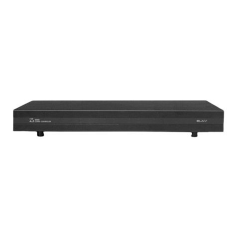
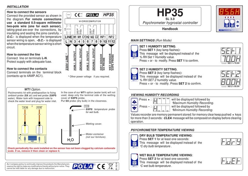
enphase IQ System Controller 3 INT User manual

2
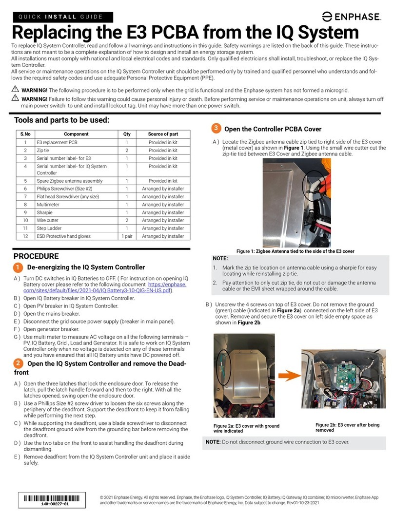
IQ System Controller 3 INT Quick Install Guide
Table of contents
Introduction
Section A
Mounting an IQ System Controller 3 INT
Tools/additional items required
Step 1: Plan a location for mounting the unit
Step 2: Minimum clearance
Step 3: Opening the door
Step 4: Mounting the IQ System Controller 3 INT
Step 5: Opening the dead front
Section B - Wiring
Internal view of IQ System Controller 3 INT
Power terminals
Recommended breaker selection
Drill conduits
Single-phase home
Field wiring of mains
Field wiring of loads
Field wiring one branch of single-phase PV
Field wiring single-phase battery and one branch
of single-phase PV
Field wiring two branches of single-phase PV
Field wiring two branches of single-phase PV
and single-phase IQ Battery
System eld wiring single-phase battery and
one branch of single-phase PV
Three-phase home
Field wiring of mains
Field wiring of loads
Field wiring three-phase PV
Field wiring three-phase PV and three-phase IQ Battery
Wiring control (CTRL) cable to headers
Control (CTRL) wiring between system components
AUX wiring: PV shedding/load control
Close dead front and install breaker ller plate
Connecting Cellular modem
System Shutdown (SSD) switch wiring
Energize IQ System Controller 3 INT
Operation
Safety
Revision history

3
IQ System Controller 3 INT Quick Install Guide
The IQ System Controller 3 INT connects the home to grid power,
the IQ Battery storage system, and solar PV. It provides microgrid
interconnection device (MID) functionality by automatically
detecting and seamlessly transitioning the home energy system
from grid power to backup power in the event of a grid failure.
It consolidates interconnection equipment and a communication
gateway into a single enclosure and streamlines the grid
independent capabilities of PV and storage installations by
providing a consistent, pre-wired solution.
The IQ System Controller 3 INT supports IQ8, IQ7, and S Series
Microinverters.
To install the IQ System Controller 3 INT, read and follow all
warnings and instructions in this guide and documents at
enphase.com/support.
Safety warnings are listed on the back of this guide. These
instructions are not meant to be a complete explanation of how
to design and install an energy storage system. All installations
must comply with national and local electrical codes and
standards. Only Enphase certied electricians shall install,
troubleshoot, or replace the IQ System Controller 3 INT.
Introduction

4
IQ System Controller 3 INT Quick Install Guide
Tools/additional items required
S. NO ITEM NAME MINIMUM QUANTITY SOURCE
1 Breakers of dierent ratings 4 Provided by installer
2 Conduits (with ttings and tting tools) - IP55 and above (for non-rear entry systems) As required Provided by installer
3 IP55 conduit ground locknut (for non-rear entry systems) 1 Provided by installer
4 M6 pilot bit 1 Provided by installer
5 Screw driver 1 Provided by installer
6 Wrench 1 Provided by installer
7 Adjustable wrench 1 Provided by installer
8 Torque wrench up to 10 N m 1 Provided by installer
9Level 1 Provided by installer
10 5/32" Allen key 2 Provided by installer
11 Conductor stripper 1 Provided by installer
12 Electrician’s hole saw (2") or punch set 1 pair Provided by installer
13 Stud nder 1 Provided by installer
14 Drill, drill bit extender As required Provided by installer
15 M6 lag bolts or screw 80 mm long (depending on attaching wall) for each wall-mount
bracket 2 Provided by installer
16 Control wire As required Provided by installer*
Section A
Mounting an
IQ System Controller 3 INT
NOTE: The IQ System Controller 3 INT weighs 15.2 kg and will
require two people to lift and align the unit.
* Recommended Electra EAS7302PHV or the LAPP 1270802

5
IQ System Controller 3 INT Quick Install Guide
Section A - Mounting an IQ System Controller 3 INT
• IQ System Controller 3 INT is IP55 rated and can be mounted both indoors and
outdoors. Install the unit where it is not exposed to direct rainfall.
• Install this product where cables from PV, incoming mains, and batteries are
easily accesible and can be terminated at the IQ System Controller 3 INT.
• This product is designed to be installed on the wall only. Do not install this product
on the ground.
• The mounting surface must be able to support 15 kg.
• Follow all local standards and regulations while choosing a location for IQ System
Controller 3 INT.
• Do not install the product on the ceiling. The unit must be accessible.
• Do not install the product on a wall with a slope of more than 10 degrees.
• Product should be installed upright. Do not install the product tilting forward.
• The product operates within an ambient temperature range from -40°C to 50°C.
• Do not install this product in a place where it is directly exposed to sunlight.
• Do not install the product in a very dusty environment.
• This product must not be installed at altitudes above 2,000 m.
• In ood prone areas, ensure that the clearance from the ground is sucient to
avoid water ingress.
10°
-40°C
+50°C
2,000 m
Step 1:
Plan a location for mounting
the unit

6
IQ System Controller 3 INT Quick Install Guide
500 mm
760 mm
158 mm
150 mm
150 mm 150 mm
900 mm
This product must be installed with clearance at the left, right, top,
bottom, and front of the product as shown in the gure.
Follow all local standards and regulations related to mounting of an
IQ System Controller 3 INT.
Section A - Mounting an IQ System Controller 3 INT
Step 2:
Minimum clearance

7
IQ System Controller 3 INT Quick Install Guide
Step 3:
Opening the door
Install the IQ System Controller 3 INT as per instructions below.
Please note the following before installing:
• The IQ System Controller 3 INT weighs 15.2 kg and will require
two people to lift and align the unit.
• Risk of injury and equipment damage. Avoid dropping the
IQ System Controller 3 INT. Doing so may create a hazard,
cause serious injury, and/or damage the equipment.
• Remove the door and keep it aside safely for ease of
installation.
Section A - Mounting an IQ System Controller 3 INT

8
IQ System Controller 3 INT Quick Install Guide
Step 4:
Mounting the IQ System
Controller 3 INT
Please note the following:
• Risk of electric shock. To maintain the warranty, do not modify
the dead front other than to remove or replace ller plates, as
needed.
• Place the IQ System Controller 3 INT on the wall so that the
mounting holes at middle of the mounting tabs are aligned with
the center of the stud. Mark the top center hole for predrilling
and keep the unit aside safely.
• Adhere to local standards. Use washers between fastener
heads and wall-mount bracket.
Ensure proper
alignment using
alignment indicator
M6
M6
80 mm
recommended
(depending on
wall thickness)
80 mm
recommended
(depending on
wall thickness)
Section A - Mounting an IQ System Controller 3 INT
NOTE: Use a drill bit extender for better access to mounting
holes during installation.
WARNING: Do not drill the conduit holes on the wall when the
unit is installed as it may lead to exposure of circuit boards to
heavy dust. Conduit holes to be marked separately on the unit
and wall for drilling.

9
IQ System Controller 3 INT Quick Install Guide
Step 5:
Opening the dead front
Before removing the dead front, ensure the IQ System Controller 3
INT is completely de-energized.
Risk of equipment damage. Do not wire the IQ System
Controller 3 INT when it is energized.
IQ System Controller 3 INT orientation
Philips screw #2
Torque: 1.4 N m
Section A - Mounting an IQ System Controller 3 INT
NOTE: Step 1 shown above may not be required during initial
installation as Cellular modem may not be connected.

10
IQ System Controller 3 INT Quick Install Guide
Backup load lugs
Manual
override
Ethernet port
IQ Gateway LED status
and buttons explained
on door label and in
Operation section of
this document
IQ System Controller
LED status explained
in the label on the
dead front
IQ Gateway USB connection
Connect at the time
of installation
Non-backup load lugs
Mains lugs
Backup loads breaker
Mains breaker
Non-backup loads breaker
Neutral terminals
Ground terminals
PV lugs
IQ Battery lugs
DER breakers
System shutdown
terminal
Once the dead front is removed the IQ System Controller 3 INT
looks like the diagram below.
DIN rails are provided to install breakers. Use conductors (line,
neutral, and ground) and breakers of proper ampacity and
protection requirements according to local codes.
Before connecting the wires, refer to the wiring table, torque
recommendations, and local codes for any specic local
requirements.
Internal view of
IQ System Controller 3 INT
IQ Gateway breaker
(pre-installed and pre-wired)
DIN rails
NOTE: Breakers for IQ Battery, mains, and non-backup/
backup loads are not supplied with IQ System Controller 3 INT
and must be purchased separately.
In Australia and New Zealand, the neutral will not be switched.
Section B - Wiring
Ensure to connect the USB cable from controller PCBA to
IQ Gateway before closing the dead front.
Ensure that wires are not pinched while re-attaching the dead
front.

11
IQ System Controller 3 INT Quick Install Guide
Connect DER, mains, and load wires as mentioned below:
• Backup loads: backup load lug (1), neutral bar (10)
• Mains: mains lugs (2), neutral bar (10), earth bar (9)
• Non-backup loads: non-backup load lugs (3), neutral bar (10),
earth bar (9)
• PV: PV L1, L2, L3 (4), neutral lugs (6) through PV breaker (B1)
• IQ Battery: IQ Battery L1, L2, L3 (5), neutral bar (10)
Power terminals
Backup load lug
Mains lugs
Non-backup load lugs
Earth bar
Neutral bar
PV neutral lugs
DER termination label
Main relay label
PV lugs
IQ Battery lugs
Section B - Wiring
NOTE: Connect L1, L2, and L3 mains, loads, and PV as
indicated on equipment labels (12, 13). Maintaining correct
phase continuity is necessary for proper operation.
CONNECTIONS WIRE SIZES
(Sq.mm)
TORQUE
(N m)
STRIP LENGTH
(mm)
IQ System Controller 3 INT lugs 2.5 - 35 6 12
Neutral and ground bar large
holes 2.5 - 35 5 10
Neutral and ground bar small
holes 2.5 - 16 2.2 10
WARNING: PV neutral must be wired to breaker before landing
on neutral lugs. Battery neutral must be wired to neutral bar.

12
IQ System Controller 3 INT Quick Install Guide
Recommended breaker selection
POSITION # PHASES CONFIGURATION (PER CIRCUIT BRANCH]
PV
PV on three-phase
4-pole PV MCB pre-installed in the unit
Must use additional 4-pole Miniature Circuit Breaker (MCB) for any additional three-phase PV branch
circuit
Must use additional 2-pole breaker for any additional single-phase PV branch circuit
PV on single-phase 4-pole PV MCB pre-installed in the unit, use for up to 2 single-phase 25 A PV branch circuits
Must use additional 2-pole breaker for any additional single-phase PV branch circuit
IQ Battery
Single-phase 1 x 1-pole MCB (20 A for 1 x IQ Battery 5 - Max 80 A for 4 x daisy-chained batteries)
Three-phase 3 x 1-pole MCB (20 A for 1 x IQ Battery 5 - Max 80 A for 4 x daisy-chained batteries)
Mains
Three-phase 1 x 3-pole MCB (Max 63 A)
Single-phase 1-pole MCB (Max 63 A)
Backup Single-phase 1-pole MCB (Max 63 A)
SCHNEIDER/CLIPSAL HAGER LEGRAND
For mains breaker
1-pole MX9MC1XXR MSN1XXR 4 034 XX
3-pole MX9MC3XXR MSN3XXR 4 035 XX
For other positions
1-pole M9MC1XX/4CB1XX-6 MSN1XX 4 034 XX
2-pole M9MC2XX/4CB2XX-6 MSN2XX 4 035 XX
3-pole M9MC3XX/4CB3XX-6 MSN3XX 4 035 XX
4-pole M9MC4XX/4CB4XX-6 MSN4XX 4 035 XX
XX is current rating XX - Current code to be identied from breaker product manual
IEC AC power circuit wiring colour codes
Wire type Colour code (IEC)
AC three-phase (L1)
AC three-phase (L2)
AC three-phase (L3)
Neutral (N)
Protective earth (PE)
ground (GND)
Single-phase (L)
(1-wire line)
Section B - Wiring
NOTE:
Breakers for IQ Battery, mains, and non-backup/backup loads
are not supplied with IQ System Controller 3 INT and must be
purchased separately.
Size the conductors and breakers according to local electrical
codes. All nal sub-circuits to follow IEC and AS/NZS colour
code indicated in this page.
Ensure that the wires connected to the breakers are tightened
with torque as recommended by the breaker manufacturer.
NOTE: IQ Gateway breaker is pre-installed and pre-wired along
with IQ System Controller 3 INT. Use this breaker to power
cycle the IQ Gateway only if required for troubleshooting.
Do not change the breaker position from slot number 19
(indicated in dead front).
Legends indicating breakers in scenario pages
Mains breaker IQ Gateway breaker
Backup breaker
Non-backup breaker
PV breaker
IQ Battery breaker

13
IQ System Controller 3 INT Quick Install Guide
Drill conduits
Section B - Wiring
Drill conduit entry holes as needed, and install conduit grounding
lugs for each opening. Be sure to reseal unused conduit entry holes
with sealing plugs.
There are options for conduit entry from bottom, the two sides, and
rear. Maximum sizes for bottom and rear conduit are also shown
below.
51 mm
51 mm40 mm
25 mm
20 mm
20 mm
16 mm
40 mm 40 mm
Right side view Left side viewBack view
Bottom view
NOTE:
Dimensions in the images indicate
the diameter of conduit drill holes.
10 mm thickness to be considered
for conduit thickness.
WARNING: Do not drill the conduit holes on the wall when the
unit is installed as it may lead to exposure of circuit boards to
heavy dust. Conduit holes to be marked separately on the unit
and wall for drilling.

14
IQ System Controller 3 INT Quick Install Guide
Section B - Wiring
Single-phase home
Field wiring of mains
Utility
grid
Main
Switch
Utility
meter
^ Breakers should be sized as per local requirements and procured
separately. They are not supplied with the IQ System Controller 3
INT.
Mains L1
Mains breaker^
IQ Gateway breaker (pre-installed and pre-wired)
PE from
mains panel
Neutral from
mains panel
NOTE: Do not change the IQ Gateway breaker position from
slot number 19 (indicated in dead front).
CONNECTIONS WIRE SIZES
(Sq.mm)
TORQUE
(N m)
STRIP LENGTH
(mm)
IQ System Controller 3 INT lugs 2.5 - 35 6 12
Neutral and ground bar large
holes 2.5 - 35 5 10
Neutral and ground bar small
holes 2.5 - 16 2.2 10
Earth bar
Neutral bar
L1
Legends
Neutral
Protective earth (PE)

15
IQ System Controller 3 INT Quick Install Guide
Section B - Wiring
^ Breakers should be sized as per local requirements and procured
separately. They are not supplied with the IQ System Controller 3
INT.
Non-backup L1
Backup L1
Backup breaker^
Non-backup breaker^
IQ Gateway breaker (pre-installed and pre-wired)
Neutral from backup panelNeutral from
non-backup
panel
NOTE: Do not change the IQ Gateway breaker position from
slot number 19 (indicated in dead front).
Backup loads
Non-backup loads
Single-phase home
Field wiring of loads
CONNECTIONS WIRE SIZES
(Sq.mm)
TORQUE
(N m)
STRIP LENGTH
(mm)
IQ System Controller 3 INT lugs 2.5 - 35 6 12
Neutral and ground bar large
holes 2.5 - 35 5 10
Neutral and ground bar small
holes 2.5 - 16 2.2 10
Neutral bar
L1
Legends
Neutral

16
IQ System Controller 3 INT Quick Install Guide
Section B - Wiring
* Pre-installed four-pole breaker to be used for PV wiring.
PV neutral lug (pre-wired to neutral pole on 4-pole breaker)
PV L1
PV breaker*
IQ Gateway breaker (pre-installed and pre-wired)
PV neutral
PV L1 PV
Single-phase home
Field wiring one branch of single-phase PV
CONNECTIONS WIRE SIZES
(Sq.mm)
TORQUE
(N m)
STRIP LENGTH
(mm)
IQ System Controller 3 INT lugs 2.5 - 35 6 12
Neutral and ground bar large
holes 2.5 - 35 5 10
Neutral and ground bar small
holes 2.5 - 16 2.2 10
NOTE: Do not change the IQ Gateway breaker position from
slot number 19 (indicated in dead front).
WARNING! PV neutral must be connected to breaker.
L1
Legends
Neutral

17
IQ System Controller 3 INT Quick Install Guide
Section B - Wiring
* Pre-installed four-pole breaker to be used for PV wiring.
^ Breakers should be sized as per local requirements and procured
separately. They are not supplied with the IQ System Controller 3 INT.
IQ Battery neutral
IQ Battery L1
NOTE: Do not change the IQ Gateway breaker position from
slot number 19 (indicated in dead front).
PV neutral
PV L1
PV IQ Battery(s)
IQ Battery lug
PV L1
PV breaker*
IQ Battery breaker^
IQ Gateway breaker (pre-installed and pre-wired)
Single-phase home
Field wiring single-phase battery
and one branch of single-phase PV
CONNECTIONS WIRE SIZES
(Sq.mm)
TORQUE
(N m)
STRIP LENGTH
(mm)
IQ System Controller 3 INT lugs 2.5 - 35 6 12
Neutral and ground bar large
holes 2.5 - 35 5 10
Neutral and ground bar small
holes 2.5 - 16 2.2 10
PV neutral lug (pre-wired to neutral pole on 4-pole breaker)
WARNING! PV neutral must be connected to breaker.
Neutral bar
L1
Legends
Neutral

18
IQ System Controller 3 INT Quick Install Guide
Section B - Wiring
* Pre-installed four-pole breaker to be used for PV wiring.
PV L1
PV breaker*
IQ Gateway breaker (pre-installed and pre-wired)
PV neutral
PV neutral
PV L1
PV L1
NOTE: Do not change the IQ Gateway breaker position from
slot number 19 (indicated in dead front).
PV
PV
Single-phase home
Field wiring two branches of single-phase PV
CONNECTIONS WIRE SIZES
(Sq.mm)
TORQUE
(N m)
STRIP LENGTH
(mm)
IQ System Controller 3 INT lugs 2.5 - 35 6 12
Neutral and ground bar large
holes 2.5 - 35 5 10
Neutral and ground bar small
holes 2.5 - 16 2.2 10
PV neutral lug (pre-wired to neutral pole on 4-pole breaker)
WARNING! PV neutral must be connected to breaker.
L1
Legends
Neutral

19
IQ System Controller 3 INT Quick Install Guide
Section B - Wiring
PV neutral
PV neutral
PV L1
PV L1
NOTE: Do not change the IQ Gateway breaker position from
slot number 19 (indicated in dead front).
PV
PV
IQ Battery neutral
IQ Battery(s)
IQ Battery L1
IQ Battery lug
PV L1
PV breaker*
IQ Battery breaker^
IQ Gateway breaker (pre-installed and pre-wired)
* Pre-installed four-pole breaker to be used for PV wiring.
^ Breakers should be sized as per local requirements and procured
separately. They are not supplied with the IQ System Controller 3 INT.
Single-phase home
Field wiring two branches of single-phase
PV and single-phase IQ Battery
CONNECTIONS WIRE SIZES
(Sq.mm)
TORQUE
(N m)
STRIP LENGTH
(mm)
IQ System Controller 3 INT lugs 2.5 - 35 6 12
Neutral and ground bar large
holes 2.5 - 35 5 10
Neutral and ground bar small
holes 2.5 - 16 2.2 10
PV neutral lug (pre-wired to neutral pole on 4-pole breaker)
WARNING! PV neutral must be connected to breaker.
NOTE: The neutral from the 2nd single-phase PV branch
is landed on the pre-installed 4-pole breaker and then
terminated at PV neutral lug (6).
Neutral bar
L1
Legends
Neutral

20
IQ System Controller 3 INT Quick Install Guide
Section B - Wiring
PV neutral
PV neutral
PV L1
PV L1
IQ Battery
neutral
IQ Battery(s)
IQ Battery L1
IQ Battery lug
PV L1
PV breaker
IQ Battery breaker
Single-phase home
System eld wiring single-phase battery
and one branch of single-phase PV
PV neutral lug (pre-wired to neutral pole on 4-pole breaker)
Neutral bar
Utility
grid
Main
Switch
Utility
meter
Mains L1
Mains breaker
IQ Gateway breaker (pre-installed and pre-wired)
PE from
mains panel Neutral from mains panel
Earth bar
PV
PV
Neutral
from
backup
panel
Neutral from
non-backup
panel
Backup loads
Non-backup loads
Non-backup L1
Backup L1
Backup breaker
Non-backup breaker
L1
Legends
Neutral
Protective earth (PE)
This manual suits for next models
1
Table of contents
Other enphase Controllers manuals

