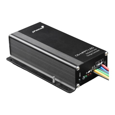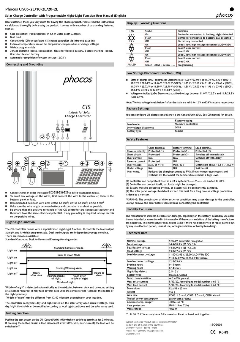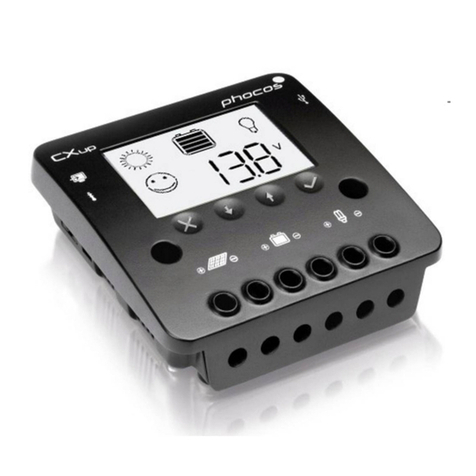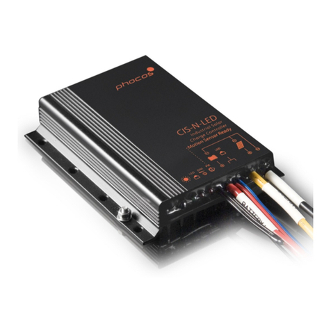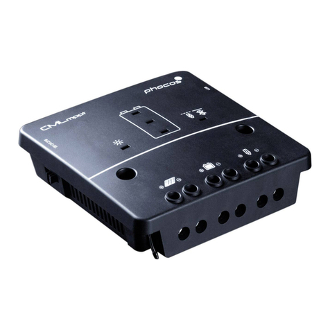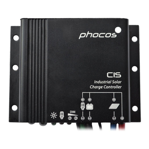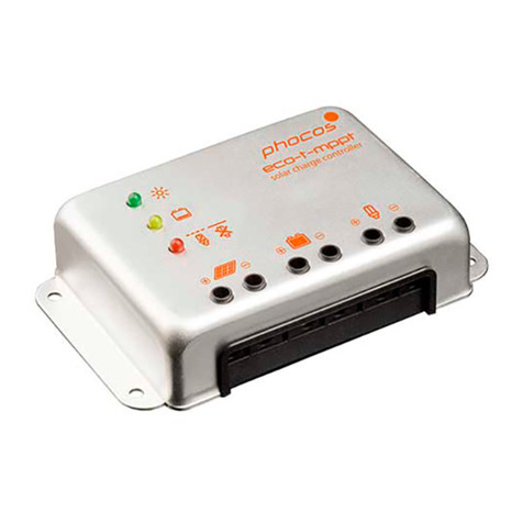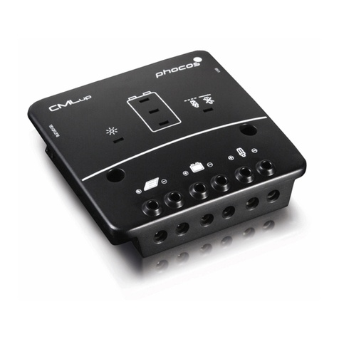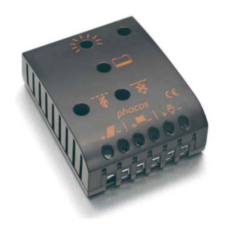
Programmable SolarChargeControllerwithNightlightFunctionCX10-1.1,CX20-1.1,CX40-1.1
UserManualEnglish,Page1
Dear Client,
Thankyouverymuch forbuyingaPhocosproduct. With yournewCX
controlleryouown astate-of-theartdevicewhichwasdeveloped
accordingto thelatestavailabletechnicalstandards. Itcomeswith a
numberofoutstandingfeatures,like:
nMultifunctionalLCdisplay
nProgrammableLowVoltageDisconnectwith newALVD(Adaptive
LowVoltageDisconnect)
nSophisticatedprogrammablenightlightfunction
nExcess EnergyManagement(EEM)forbetterutilizationofyoursolar
system
nCompleteelectronicprotection
Thismanualgivesimportantrecommendationsforinstalling,usingand
programmingaswellasremediesincaseofproblemswith thecontroller.
Read itcarefullyin yourown interest andmindthesafetyandusage
recommendationsattheendofthismanual.
Description ofFunctions
nThechargecontrollerprotects thebatteryfrombeingovercharged
bythesolar arrayandfrom beingdeepdischargedby theloads.The
chargingcharacteristicsincludeseveralstageswhich includesauto-
maticadoption totheambienttemperature.
nThechargecontrolleradjusts itselfautomaticallyto12Vor24Vsystem
voltage.
nThepushbutton allowsswitchingtheload on andoff.
nThechargecontrollercan beprogrammedforlightingapplications.
nThecontrollerprovidesacontroloutputforspecialloadsthatmake
useofexcessenergy, likethePhocosSF32EandSF50ESolar Refrigera-
tors.Additionally, ithasaserialinterface whichcan beusedwith an
optionalinterface adapter(CX-I).
nThechargecontrollerhasanumberofsafetyanddisplayfunctions.
MountingandConnectingthe ChargeController
Theregulatorisintendedforindooruseonly.Protectitfromdirect
sunlightandplaceitin adryenvironment. Neverinstallitin humidrooms
(likebathrooms).
Theregulatormeasurestheambienttemperatureto adoptthecharg-
ingvoltages,thereforeitmust beinstalledinthesame roomasthe
battery.
Theregulatorwarmsupduringoperation.Itshallbeinstalledon anon
flammablesurface only.
REMARK:Connectthecontrollerby followingthestepsdescribedbelow
to avoidinstallationfaults.
1
Open theterminallid.
2
Removethescrewsfromthestrain relief andtake
offthestrain relief bridges.
3
Mountthecontrollerto thewallwith
screwsthatfitto thewallmaterial.
Usescrewswith 4to5mm shaftand
max. 9mm head diameter,no
countersunk.
Mindthatthescrewshavetocarry
alsotheforceappliedby thewiring.
Mindalso theminimumrequired
distance to floorandceiling,thisis
necessaryforventilation reasons.
ADINRailmountingplateisavail
asan accessory(CX-DR2). Thisallows
mountingthecontrolleron astan-
dard 35mm DINrail.Usethescrews
suppliedwiththemountingplateto
fixit to thecontroller.
>10cm
>4
>10cm
>4
4
Connectthewiresleadingto thebatterywith
correctpolarity.To avoidanyvoltageon the
wires, firstconnectthecontroller,then thebattery.
Mindtherecommendedwirelength(min 30 cm
tomaxapprox.100 cm)andthewiresize:
CX10: min2,5mm
CX20: min4mm
CX40: min10mm
Wrongpolaritywillcauseapermanentwarning
sound.
WARNING:Ifthebatteryisconnectedwithreversepolarity,theload
terminals willalso havethewrongpolarity. Neverconnectloadsduring
this condition!
REMARK:Thecontrollerhasabuilt-involtagedropcompensation which
automaticallycompensatesbatterywirevoltagedropsofupto 250mV.
REMARK:Mindtherecommendationsofyourbatterymanufacturer.We
stronglyrecommendconnectingafusedirectlyto thebattery to protect
anyshortcircuitatthebattery wiring.Thefusemusttakethecharge
controllernominalcurrent:
CX10: 15A,CX20: 30A,CX40: 50A
5
Connectthewiresleadingto thesolar arraywith
correctpolarity.To avoidanyvoltageonthe
wires,firstconnectthecontroller, thenthesolar
array.
Mindtherecommendedwiresize:
CX10: min2,5mm
CX20: min4mm
CX40: min10mm
REMARK:placepositive andnegativewireclosetoeachotherto
minimizeelectromagneticeffects.
REMARK:Solar panelsprovidevoltageassoonasexposedtosun light.
Mindthesolarpanelmanufacturer’srecommendationsin anycase.
66
Toavoidvoltageattheload terminal,pushthe
button toshutofftheload output.Connectthe
wiresleadingto theloadswith correctpolarity.
Mindtherecommendedwiresize:
CX10: min2,5mm
CX20: min4mm
CX40: min10mm
7
Fasten thestrainrelieves.
8
IfyouintendtousetheExcessEnergy
Managementoutput,followthesesteps:
a. Removethegreenterminalblock in the
terminalcom
down.
b. Mounttheexcess energysignalwiresas
shownin thepicturebeside.
c.Connectthesignalwiresto theexcess
energymanagementinputoftheap-
propriateload(e.g.PhocosSolar coolers
SF32E, SF50E)
d. Reconnectthegreenterminalblockto
theCX
9
Closetheterminallid.
Nowyou havesuccessfullyconnectedyourCX
controller.
Grounding theSolarSystem
Beawarethatthepositive terminalsoftheCXcontrollerareconnected
internallyandthereforehave thesame electricalpotential.Ifany
groundingisrequired,alwaysdo thison thepositivewires.
REMARK:IftheCX isusedin a
vehiclewhichhasthebatterynegativeon
thechassis,loadsandsolar panels connectedto theregulatormust not
haveanelectricconnection to thecar body.Otherwisetheovercharge
protection, theLowVoltageDisconnectandtheelectronicfusefunc-
tion ofthecontrolleris shortcircuited.
StartinguptheController
SelfTest
Assoon asthecontrolleris suppliedwith powereitherfromthebattery
orthesolar array,itstarts aselftestroutine.Thisisindicatedfirstby
runningLCDbarsforapprox.0.5seconds,andthen thefirmwareversion
isdisplayedin codedsymbols foraboutanothersecond(thisis for
service purposesonly).Then thedisplaychangestonormaloperation.
SystemVoltage
Thecontrolleradjusts itselfautomaticallyto12V or24V systemvoltage.
Assoon asthevoltageatthetimeofstart-upexceeds20.0V, the
controllerimpliesa24 V system.
Ifthebattery voltageisnotwithin thenormaloperation range(approx.
12to15.5Vorapprox.24to31 V)atstart-up, astatusdisplayaccording
to thesection ERROR DESCRIPTIONoccurs.
BatteryType
Thecontrolleris presetto operatewith lead acidbatterieswith liquid
electrolyte.IfyouintendtouseaVRLAbattery (GELtype)you can
adjustthecontrollerinProgrammingMenu 1(seeback page). The
equalization chargeisdeactivatedthen.In caseofanydoubts consult
yourdealer.
Recommendationsfor Use
Theregulatorwarmsupduringnormaloperation.Ifthereis insufficient
ventilation (e.g.inaninstallation cabinet),thecontrollerlimits thesolar
chargecurrenttopreventoverheating.
Theregulatordoesnotneedanymaintenanceorservice.Removedust
with adrytissue.
Itis importantthatthebattery getsfullychargedfrequently(atleast
monthly). Otherwisethebattery willbepermanentlydamaged.
Abatterycanonlybefullychargedifnottoo muchenergyis drawn
duringcharging.Keepthatinmind,especiallyifyou installadditional
loads.
DisplayFunctions
In normaloperationmodethecontrollerdisplaysthestateofcharge
(availableenergy)ofthebattery.Anychangeofthestateofcharge
(SOC)to alowerstatusisadditionallysignalledacoustically.
System conditionsaredisplayedasfollows:
25x5x3x2x
1x
<10%
Flashes
10...35%35...60%
60...80%>80%
Thepercentagecorrespondsto theavailableenergyuntilLowVoltage
Disconnectin relation to afullychargedbattery.
Aslongasthesolar array suppliesenoughvoltagetochargethe
battery,thisis indicatedby up-movingbarsalternatelyto thestateof
chargedisplay.
In normaloperationtheloadscan beswitchedon andoffby pushing
thebutton. Thisis indicatedin thedisplay:
manuallyON
Specialconditionsareshownin theLCdisplayiftheLowVoltage
Disconnectfunctionshuts off theload outputorin caseofvariousother
errorconditions. See section ERROR DESCRIPTIONfordetails.
LowVoltageDisconnectFunction
Thecontrollerhas5differentmodestoprotectthebatteryfrom being
deepdischarged:
Mode1Disconnectat11.4V(atnominalload current)upto11.9V
(atnoload current). Normaloperation modeforgoodbat-
teryprotection.
Mode2Disconnectat11.0V(atnominalload current)upto11.75 V
(atnoload current). Modewithlowerdisconnection point.
Batteryiscycleddeeper,thiscan shorten battery lifetime.
Mode3Disconnectat11.0Vto12.2V dependingonload current
andpreviouschargingcycles. Thisadaptivemodeleadsto
longerlifetime ofthebatterybecauseitallowsrecovery of
thebatteryby fullrecharge.Maximumbattery life.
Mode4:Disconnectat11.5Vfixedsetting.Appropriateifbypassloads
drawcurrentdirectlyfrom battery.
Mode5:Disconnectat11.0Vfixedsetting.Appropriateifbypassloads
drawcurrentdirectlyfrom battery.Modewith lowerdiscon-
nectionpoint.Battery is cycleddeeper,thiscanshorten bat-
terylifetime.
Thecontrollerispresetto Mode1fromthefactory. Use
ProgrammingMenu2. tochangethesetting(seeback page).
In caseofdoubtswhichmodetochoose, consultyourdealerbecause
thishasto beevaluateddependingonthebatteryused.
Excess EnergyManagementFunctionEEM
Thecontrollerprovidesabuilt-inexcess energymanagementfunction.
This function,incombination withespeciallydesignedloads(e.g.
PhocosSolar Refrigerators/CoolersSF32E,SF50E),allowstomakeuseof
excessenergywhichwouldbelostotherwisebecauseoftheover-
chargeprotection ofthebattery.Abetterutilization ofthesolar system
isthebenefit.Also thebattery treatmentisimprovedbecausemore
energycomesdirectlyfromthesolarpanelinstead ofthebattery.Ask
you dealeraboutavailableloadsthatcanmakeuseofexcess energy.
To connectyourExcess Energyload with thecontroller,see picture8
(signalwires).
NightlightFunction
TheCXcontrollercomeswith asophisticatednightlightfunction. It
controlstheload outputatnightandiswidelyprogrammable.
Thereare2modesavailable:
DUSK TODAWNandEVENING/MORNING.Themodecanbeselectedin
ProgrammingMenu3.
Lighton
Lightoff
Lightoff
Lighton
Number
of hours Number
ofhours
or or
timeto
midofnight timeafter
midof night
Midofnight
IfEVENING/MORNINGisselected,ProgrammingMenu 5allowschoos-
ingtheMORNINGtimingbehaviour,andProgrammingMenu4allows
choosingtheEVENINGtimingbehaviour.
Mindthattheload outputis switchedoffassoon asthebattery has
reachedtheLowVoltageDisconnectthreshold.TheLowVoltage
Disconnecthaspriorityabove thenightlightfunction.
“Midofnight”is detectedautomaticallyasthemiddlebetweendusk
anddawn,no realtimesettingis required.Itmaytakesome daysuntil
thecontrollerhas “learnt”midnight.Thismethodcancausesome
inaccuracybutavoidsanyclockreadjustment.Thecontroller’s “Midof
night”canbedifferentfromtherealtime midnightdependingon your
location.
