Next, define the behavior for each of eight relay outputs.
Each relay may be set for momentary or latching output.
Check the Pair Relay Channels box in order for the relays
to act as mutually exclusive pairs. When this box is
checked, a command to one relay will cause the second
relay to de-energize.
Note: When the Pair Relay Channels box is checked, it is
recommended to configure the two paired relays with the same behavior (Latching / Latching or
Momentary / Momentary). If one relay is configured as Latching and the other as Momentary, a
command to the momentary relay will de-energize the latching relay. After the momentary
command is finished, both relays will remain de-energized until a new command is issued to
one of the relays.
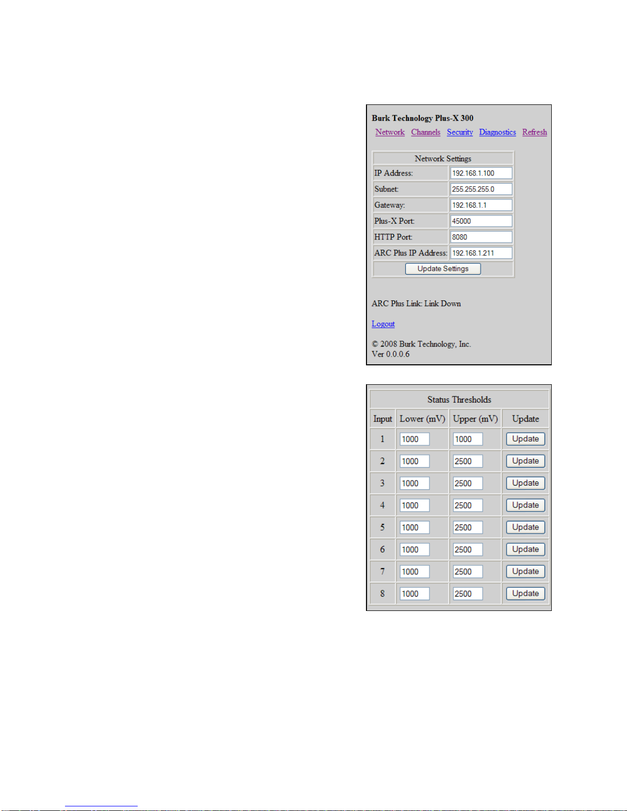
Security
Navigate to the Security page to set the
password for the Plus-X 300. This password is
used only to access the Plus-X configuration
screens. ARC Plus user names and passwords
are set up using AutoLoad Plus software.
The Plus-X 300 user name is always admin.
Adding Plus-X Channels to the ARC Plus
Now that you have configured the input and output channels on the Plus-X 300, these channels
may be added to the ARC Plus site using AutoLoad Plus. To add Plus-X 300 channels to the
ARC Plus:
1. Launch AutoLoad Plus and connect to the ARC Plus site to which the Plus-X 300 is
linked.
2. From the Edit menu, select Plus-X Devices…and click New.
3. When the Plus-X Settings window appears, select Plus-X 300 from the device type drop-
down. Enter a description of the Plus-X 300 for your own reference, followed by the IP
address and Plus-X port, both of which are already configured on the Plus-X 300.
4. Check the box marked Map Default Set of Channels to add all eight inputs and eight
relays to the ARC Plus. If you are not using all Plus-X 300 channels or if you do not wish
for them to appear in sequential order, you will need to manually map these channels
later. In this case, leave the Map Default Set of Channels box unchecked.
5. Press OK to close the Plus-X Settings window. Press OK to close the Plus-X Devices
window.
6. To manually map Plus-X 300 channels to the ARC Plus, click the Metering, Status or
Commands tabs, as appropriate. Locate an unused channel and click the […] button in
the Source column. This will bring up the Source dialog box. Click the Plus-X button and
choose the Plus-X 300 channel you wish to use. At least one meter channel and one