ensol ES2H/2.65 User manual

Installation instruction
For flat solar collectors
on flat roof or foundation.
Installation instruction for flat solar
collectors on flat roof or foundation
01/2019 Read before installation

2
Installation
i
nstruction
for flat collectors on flat roof or foundation.
The installation instruction applies to collectors:
Flat
collector
Installation
setting
Absorber
type
Absorber
material
*
1
width
height depth Collector
mass Surface
Connecting
system
Li uid
content
Optimal
flow min.
- max.
symbol - - - A B C m S - V m
unit - - - mm mm mm kg m
2
- dm
3
dm
3
/h
E 2H/2,65
Al-Cu horizontal meander Al-Cu 2356 1120 85 49 2,65 o-ring v.1. 2,20 75 - 105
E 2V/2,65
Al-Cu vertical meander Al-Cu 1120 2356 85 49 2,65 clamp 2,20 75 - 105
E 2V/2,65 vertical meander Cu-Cu 1120 2356 85 49 2,65 clamp 2,20 75 - 105
E 2V/2,0
HE vertical meander Cu-Cu 1006 2007 85 38 2,02 clamp 1,80 60 – 90
E 2V/2,0
AL vertical meander Al-Al 1006 2007 85 38 2,02 o-ring v.1. 1,80 40 - 60
EM2V/2,0
Al-Cu vertical meander Al-Cu 1006 1988 85 38 2,0 clamp 1,80 60 - 90
EM2V/2,0 vertical meander Cu-Cu 1006 1988 85 38 2,0 clamp 1,80 60 - 90
EM1V/2,0
Al-Cu vertical double
harp Al-Cu 1006 1988 85 40 2,0 clamp 1,80 60 - 90
EM1V/2,0 vertical double
harp Cu-Cu 1006 1988 85 40 2,0 clamp 1,80 60 - 90
E 1V/2,0 vertical double
harp Cu-Cu 1006 2007 85 40 2,02 clamp 1,80 60 - 90
E-PVT 2,0
v.1 vertical roll-bond
Al-Al 1006 2007 85 37 2,02 o-ring v.1 1,2 90
*
1
Cu-Cu – high-selective sheet=Cu, hydraulic system=Cu;
Al-Al – high-selective sheet=Al, hydraulic system=Al;
Al-Cu – high-selective sheet=Al, hydraulic system=Cu.

3
Installation
i
nstruction
for flat collectors on flat roof or foundation.
1. Introduction
Lightning protection installation
In the case where the height of the collector installation exceeds 20m and the building is not
e uipped with lightning protection, all of the electrically conductive elements should be
connected to an earth rod (minimal earth rod cross-section – 16mm
2
), and then to the
e ualizing potential.
When the collector installation height does not exceed 20m, the lightning protection system
is not re uired.
If the building is e uipped with the lightning protection, the connection of the solar
installation with the lightning protection should be checked. This procedure should be
performed by an electrician.
Recycling
Worn out solar collectors can be returned to the manufacturer.
The manufacturer will dispose the returned collectors in an environmentally sound manner.
2. afety during installation
Before starting the installation it is necessary to get promptly acquainted with the
safety precautions!
2.1 Notes included in the instruction
The installation instruction includes important information concerning safety and proper
positioning of the collectors on the roof as well as the proper execution of the hydraulic
connection.
The drawings and the information included in the instruction apply to a vertical and
horizontal installation of collectors.
The installation of collectors described in the instruction may only be performed by
ualified persons who have expertise in a range of gas and water installations.
Upon the completion of works, the installer should hand over the installation instruction to
the customer and present in a comprehensible manner the principles of operation and Note
essential to a proper operation of the solar installation.
2.2 Application
This instruction includes a description of an installation set for installation of collectors on a
flat roof or a foundation with the inclination ranging from 30°
to 75°.
The installation set shall be used only for solar collectors installation, it must not be used
for installation of other devices on the roof. The installation of solar collectors only on a
supporting structure guarantees safety.
Collectors installed on the ground must be attached to the ground by the means of
foundation and transitional construction (Not included in the standard installation set).
The minimum distance between the bottom edge of a collector to the ground surface must
be min.40cm.

4
Installation
i
nstruction
for flat collectors on flat roof or foundation.
3. Before installation
Note
Due to the fact, that installation works on a roof can be dangerous it is recommended to hire
a roofing contractor company to carry them out.
BURN HAZARD
If collectors and installation materials are exposed to solar radiation for a long time, there is
a risk of getting burnt on the hot elements.
In order to avoid the danger of getting burnt it is appropriate to:
- use protective clothing,
- cover the collectors and installation elements with a tarpaulin (what limits the heat up
from the sun rays).
Caution!
If the collectors are packed on a transport pallet vertically,
use the following unloading instructions.
Read the instruction before proceeding to unloading of the vertical collector pallet!
1) The first stage before unloading is to set the transport pallet on a flat surface. Figure 1.1 shows the transport
pallet set on a flat consolidated foundation
2) The second stage of unloading is to put a 30mm high board under the transport pallet so that the inclined
transport pallet becomes stable. Figure 2.1 presents the conditions that the transport pallet should fulfill
before unloading.
3) After fulfilling the conditions for setting the transport pallet, the collectors can be unloaded. Take special
caution while unloading (COLLECTOR ARE PROTECTED ONLY AT THE FRONT OF THE
PALLET). In the picture marked as 3.1, the transport pallet ready for unloading is presented.
4) After removing a collector, the next one should be absolutely protected until it is unloaded.

5
Installation
i
nstruction
for flat collectors on flat roof or foundation.
1.1 Shipment position 2.1 Unloading position
3.1 Transport pallet ready for unloading
3.1 The delivery completeness
Before installation it is necessary to check if the delivery is complete (see figure below) and
the delivered components are not damaged.
- in case of discovering any damages of element or part the replacement of a such should
be immediately provided,
- the replacement must be provided only with the application of original spare parts

6
Installation
i
nstruction
for flat collectors on flat roof or foundation.
3.1.1 Installation set for vertical collectors
3.1.2 Installation set for horizontal collectors

7
Installation
i
nstruction
for flat collectors on flat roof or foundation.
3.1.3 Installation set delivery completeness – flat roof / foundation „on compensator”
Flat roof
installation
set
Ba
t
tery
No.
Na
me
unit
1
2
3
4
5
6
7
8
9
10
1.
Assembly
triangle
pc
.
2
3
4
5
6
7
8
9
10
11
2.
Side fastening
plate PMB35
pc.
4
4
4
4
4
4
4
4
4
4
3.
Inter-collector
fastening
plate
PMM112
pc.
0
2
4
6
8
10
12
14
16
18
4.
1
Vertical
collectors
2,0m
2
Multi-slot
section
l=2240
pc.
2*1120
2*2240
2*1120
+
2*2240
4*2240
2*1120
+
4*2240
6
*2240
2*1120
+
6*2240
8
*224
0
2*1120
+
8*2240
10
*22
40
4
.
2
Vertical
collectors
2,65m
2
Multi-slot
section
l=2460
pc.
2*
1230
2*
2460
2*
12
30
+ 2*
2460
4*
2460
2*
12
30
+
4*2440
6*
2460
2*
12
30
+
6*
2460
8*
2460
2*
12
30
+ 8*
2460
10*
2460
4
.
3
Horizontal
collectors
2,65m
2
Multi-slot
section
l=2500
pc.
2
*
2500
4
*
2500
6
*
250
0
8
*
2500
1
0
*
2500
12
*
2500
14
*
2500
16
*
2500
18
*
2500
20
*
2500
5
.
Fastening
holder
UM114
pc.
2
4
6
8
10
12
14
16
18
20
6
.
Mounting
bolt set 1
set
4
8
12
16
20
2
4
28
32
36
40
- tee head bolt
inox 8x20
- inox plate
M8
- resilient
plate inox M8
- inox nut M8
7
.
Mounting bolt
set 2 (triangle)
set
4
6
8
10
12
14
16
18
20
22
- tee head bolt
inox 8x20
- wide plate
inox M8
- resilient plate
inox M8
- inox nut M8
8
Installation
i
nstruction
for flat collectors on flat roof or foundation.
3.1.4 The delivery completeness of Installation set – flat roof / foundation „on pipe union”
Flat roof
installation
setInstallation set
Bat
tery
Lp.
No.
Name
unit
1
2
3
4
5
1.
Assembly
triangle
pc.
2
3
4
5
6
2.
Side fastening
plate PMB35
pc.
4
4
4
4
4
3.
Inter
-
col
lect
or
fastening plate
PMM112
pc.
0
0
0
2
2
4.
Mount
ing
inter
-
collector plate
PMM79
pc.
0
2
4
4
6
5.1
Vertical
collectors
2,0m
2
Multi-
slot section
l=2240
p
c.
2*1120
2*2240
2*1120
+
2*2240
4*2240
2*112
0
+
4*2240
5.2
Horizon
t
al
collectors
2,65m
2
Multi-slot
section l=
2460
pc.
2*1220
2*2440
2*1220
+
2*2440
4*24
40
2
*1
2
20
+
4*2440
5.3
Horizontal
collectors
2,65m
2
Multi-slot
section l=2500
pc.
2
*
2500
4
*
2500
6
*
2500
8
*
2500
10
*
2
500
6.
Fastening
holder UM114
pc.
2
4
6
8
1
0
7.
Mo
unting bolt
set 1
S
et
4
8
12
16
20
-
tee head bolt
inox 8x20
-
plate
inox
M
8
-
resilient
plate
inox M8
-
nut
inox M8
8.
Mounting bolt
set 2 (triangle)
set
4
6
8
10
12
-
te
e head
b
olt
inox 8x20
-
wide
plate
inox
M8
-
resil
ient
plate
inox M8
-
nut
inox M8

9
Installation
i
nstruction
for flat collectors on flat roof or foundation.
3.1.5 Vertical collectors Installation set – light version (economical without inclination
angle adjustment and bottom strut positioning spacing of the triangle feet)
The collation applies to the part of the instruction only for installation of collectors
with the surface of 2,0m
2
on supporting structure on a roof or flat surface in light
version, which is an additional version.

10
Installation
i
nstruction
for flat collectors on flat roof or foundation.
3.1.6 The delivery completeness of Installation set for vertical collectors light version „on
compensator”.
Installation set – light version Battery
Lp.
No. Name uni
t 1 2 3 4 5
1
Vertical triangle light flat
roof pc. 2 3 4 5 6
2
Fastening holder UM114 pc. 2 4 6 8 10
3
Multi-slot section
Collector 2.0
m
2
lm 2*1,12 2*2,24 2*2,24 +
2*1,12 4*2,24 4*2,24 + 2*1,12
4
Multi-slot section
Collector 2.65
m
2
lm 2*1,23 2*2,46 2*2,46 +
2*1,23 4*2,46 4*2,46 + 2*1,23
5
Multi-slot section
connector pc. - - 2 2 4
65
Side fastening plate
PMB35
pc. 4 4 4 4 4
7
Inter-collector fastening
plate PMM112
pc. - 2 4 6 8
8
Tee head bolt set 1 set 4 6 8 10 12
Tee head bolt INOX
M8x20
Nut INOX M8
Resilient plate INOX M8
Plate INOX M8
9
Mounting bolt set 2 set 4 6 8 10 12
- tee head bolt INOX
M8x20
- nut INOX M8
- resilient plate INOX M8
- wide plate INOX M8
Optional elements for
light version
10 Angle strut al.35x35 pc. 1 2 3 4 5
11 Strut bolt set set 2 3 4 5 6
- bolt INOX M8x55
- nut INOX M8
- resilient plate
- plate INOX M8

11
Installation
i
nstruction
for flat collectors on flat roof or foundation.
3.1.7 The delivery completeness of Installation set for vertical collectors light version “on pipe
union”
Installation set - light
version Battery
No. Name unit 1 2 3 4 5
1
Vertical triangle light flat
roof pc. 2 3 4 5 6
2
Fastening holder UM114 pc. 2 4 6 8 10
3
Multi-slot section 2.0
m
2
mb. 2*1,12 2*2,24 2*2,24 + 2*1,12
4*2,24 4*2,24 + 2*1,12
4
Multi-slot section
Collector 2.65
m
2
lm 2*1,23 2*2,46 2*2,46 + 2*1,23
4*2,46 4*2,46 + 2*1,23
5
Multi-slot section
connector pc. - - 2 2 4
6
Side fastening plate
PMB35
pc. 4 4 4 4 4
7
Inter-collector fastening
plate PMM112
pc.
- - - 2 2
8
Inter-collector fastening
plate PMM79
pc.
- 2 4 4 6
9
Tee head bolt set 1 set 4 6 8 10 12
Tee head bolt INOX
M8x20
Nut INOX M8
Resilient plate INOX M8
Plate INOX M8
10
Mounting bolt set 2 set 4 6 8 10 12
- tee head bolt INOX
M8x20
- nut INOX M8
- resilient plate INOX M8
- wide plate INOX M8
Optional elements for
light version
11 Angle strut al.35x35 set 1 2 3 4 5
12 Strut bolt set set 2 3 4 5 6
- bolt INOX M8x55
- nut INOX M8
- resilient plate
- plate INOX M8
12
Installation
i
nstruction
for flat collectors on flat roof or foundation.
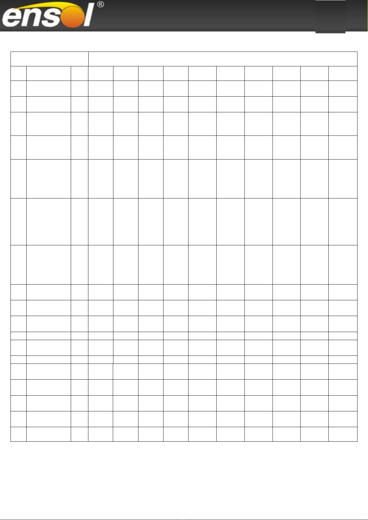
3.1.8 The delivery completeness for clamp connecting system „on compensator” for double
harp collector
Connect
i
ng system for
do
uble
-
harp co
l
lec
tors
Bat
tery
x
No
.
Name
unit
1
2
3
4
5
1.
Cross f
itting
fi22
x GZ3/4”
w
ith
a vent
pc.
1
1
1
1
1
2.
Clamping elbow
fi22 x GZ3/4”
pc.
1
1
1
1
1
3.
Com
pensator
fi22 x fi22
pc.
0
1
2
3
4
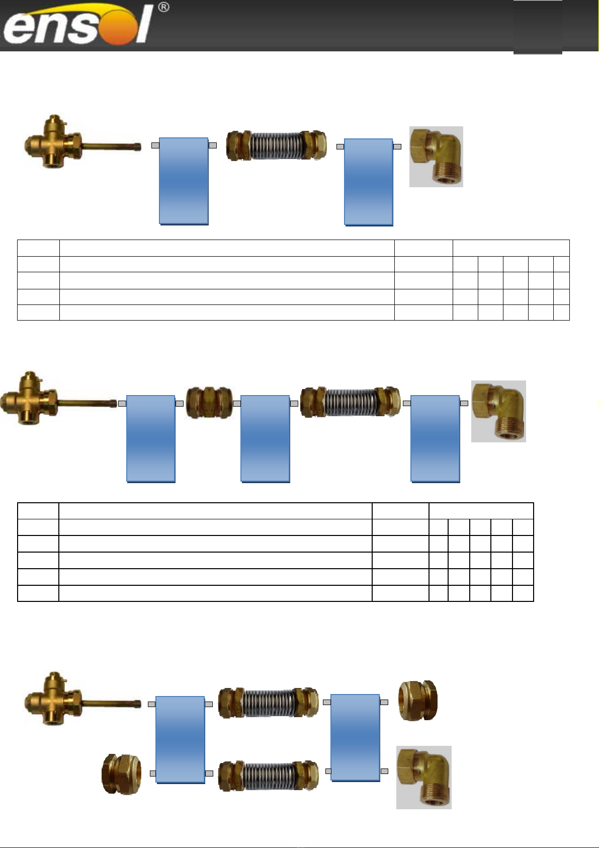
3.1.9 The delivery completeness for clamp connecting system „on a pipe union” for double
harp collector
Conn
ect
ing system
for
do
uble
-
harp coll
ec
to
rs
Battery
x
No
.
Name
unit
1
2
3
4
5
1.
E
lbow
f
i22
x GZ3/4”
pc.
1
1
1
1
1
2.
Pipe union
fi22 x fi2
2
pc.
0
1
2
2
3
3.
C
omp
ensator fi22 x fi22
*
pc.
0
0
0
1
1
4.
Cross fitting
fi22 x GZ
3/4
”
w
ith a vent
pc.
1
1
1
1
1
*In case of a battery with 4 and 5 collectors, the compensator needs to be placed between 2 and 3 collector.
3.1.10 The delivery completeness for clamp connecting system „on a compensator” for a
meandric collector – vertical installation
3
.
1
.
2
.
1
.
2
.
3.
4
.
4
.
1
.
2
.
3.

13
Installation
i
nstruction
for flat collectors on flat roof or foundation.
3.1.11 The delivery completeness for clamp connecting system „on a pipe union” for
meandric collector – vertical installation
Con
nect
ing system fo
r meandric
collector
s
Batt
ery
x
No
.
Name
unit
1
2
3
4
5
1.
Elbow
fi22 x GZ
3/4”
pc.
1
1
1
1
1
2.
P
i
pe union
fi22 x fi22
pc.
0
2
4
4
6
3.
Compensato
r
fi22 x fi
22
*
pc.
0
0
0
2
2
4.
Cross fitting
fi22 x GZ3/4”
w
ith a vent
pc.
1
1
1
1
1
5.
C
lamping end c
ap
fi22
pc.
2
2
2
2
2
*In case of a battery with 4 and 5 collectors, the compensator needs to be placed between 2nd and 3rd collector.
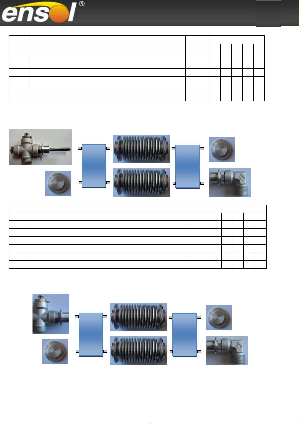
3.1.12 The delivery completeness for o-ring v.1 connecting system „on compensator” for
meandric collector – horizontal installation
Connect
ing
system for meandric collector
s
Battery
x
N
o
.
Na
me
unit
1
2
3
4
5
6
7
8
9
10
1.
Clamp
ing end cap
fi22
pc.
2
2
2
2
2
2
2
2
2
2
2.
Clamping elbow
fi2
2 x
GZ3
/4”
p
c.
1
1
1
1
1
1
1
1
1
1
3.
Compensato
r
fi22 x fi
22
pc.
0
2
4
6
8
10
12
14
16
18
4.
Cross
fit
ting
fi22 x GZ3/4”
w
ith a vent
pc.
1
1
1
1
1
1
1
1
1
1
4
.
5
.
2
.
1
.
3
.
1
.
2
.
3
.
4
.
14
Installation
i
nstruction
for flat collectors on flat roof or foundation.
Connecting syst
e
m for meand
ric coll
ectors
Battery
x
No
.
Name
unit
1
2
3
4
5
1.
End cap
o
-
ring v.1
pc.
2
2
2
2
2
2.
Elb
ow
o
-
ring v.1
pc
.
1
1
1
1
1
3.
Compensat
or
o
-
ring v.1
pc.
0
2
4
6
8
4.
Cross f
i
tting with a
vent
o
-
ring v.1
pc.
1
1
1
1
1
5.
Gasket
o
-
ring v.1
pc
.
4
8
12
1
6
20
6.
C
lasp
o
-
ring v.1
pc.
4
8
12
16
20
3.1.13 The delivery completeness for o-ring v.1 connecting system „on compensator” for
meandric collector Al-Al – vertical installation
Connecting system for meandric collectors Battery x
No. Name unit 1 2 3 4 5
1. End cap
o-ring v.1
pc. 2 2 2 2 2
2. Elbow
o-ring v.1
pc. 1 1 1 1 1
3. Compensator
o-ring v.1
pc. 0 2 4 6 8
4. Cross fitting with a vent
o-ring v.1
pc. 1 1 1 1 1
5. Gasket
o-ring v.1
pc. 4 8 12
16
20
6. Clasp
o-ring v.1
pc. 4 8 12
16
20
3.1.14 The delivery completeness for o-ring v.1 connecting system „on compensator” for
hybrid collector – vertical installation
1
.
2
.
3
.
4
.
1
.
2
.
3
.
4
.

15
Installation
i
nstruction
for flat collectors on flat roof or foundation.
Connecting system Battery x
No. Name unit 1 2 3 4 5
1. End cap
o-ring v.1
pc. 2 2 2 2 2
2. Elbow
o-ring v.1
pc. 1 1 1 1 1
3. Compensator
o-ring v.1
pc. 0 2 4 6 8
4. Tee connector with a
o-ring v.1
vent pc. 1 1 1 1 1
5. Gasket
o-ring v.1
pc. 4 8 12 16
20
6. Clasp
o-ring v.1
pc. 4 8 12 16
20
3.2 hipment and storage
- during shipment the collector connectors are protected by rubber caps,
- the collectors should be stored in a dry place. If the collectors are stored outside they
should be protected from atmospheric agents.
3.3 Technical documentation
Solar installation set consists of different components. Before installing any of them you
should become familiar with an ade uate instruction. Installation instructions are attached
to a given device or piece of e uipment.
- installation instruction for solar collectors,
- installation instruction for a pump group,
- installation instruction for a solar controller,
- installation instruction hot water tank.
3.4 Tools and additional equipment
- level gauge,
- harness with a safety cable (for work at heights),
- scaffolding, a roof ladder or a crane.
3.5 Collector location
Potential uantity of the absorber radiation depends on a proper location of the absorber in
relations to incident rays. Collector surface horizontal position to radiation is an optimum
manner.
Recommended location of a collector:
- inclination angle:
40 – 45
o
for yearlong installations
approx. 30
o
for installations used during summer
approx. 60
o
for installations used during winter
- positioning of a collector in the southern direction (or approximate to the southern direction).
Collectors recommended, optimal angle of inclination ranges from 30° to 75°.
The admissible inclination angle of collectors ranges from 15° to 90°. It is recommended to
install collectors on a south-facing roofs. During installation, particular attention should be paid
to protection of the collectors against strong winds.
The admissible snow and wind load amount is max. 2,0 kN/m².
A collector field should be located in a manner that the absorber will not be shadowed by the
16
Installation
i
nstruction
for flat collectors on flat roof or foundation.
adjacent buildings, trees, etc.
In case of a larger number of collector fields it is important for the front row not to shadow the
one in the back.
3.6 The warranty conditions of installation and use of collectors can be found in the
warranty card of a particular collector.
3.7 Application of collectors in coastal areas.
For collectors that are installed up to 500LM from the coastline – lack of warranty for an
absorber with a high-selective coat.
It is recommended to apply collectors with an absorber with an increased resistance to
seawater e.g. Mirosol TS.
4. upporting construction installation
4.1 Inclination angle of the collectors
4.1.1 Roof or flat surface
In case of collector installation on a roof or a flat surface, the inclination angle of an
installing system corresponds directly to the assumed inclination of collectors.
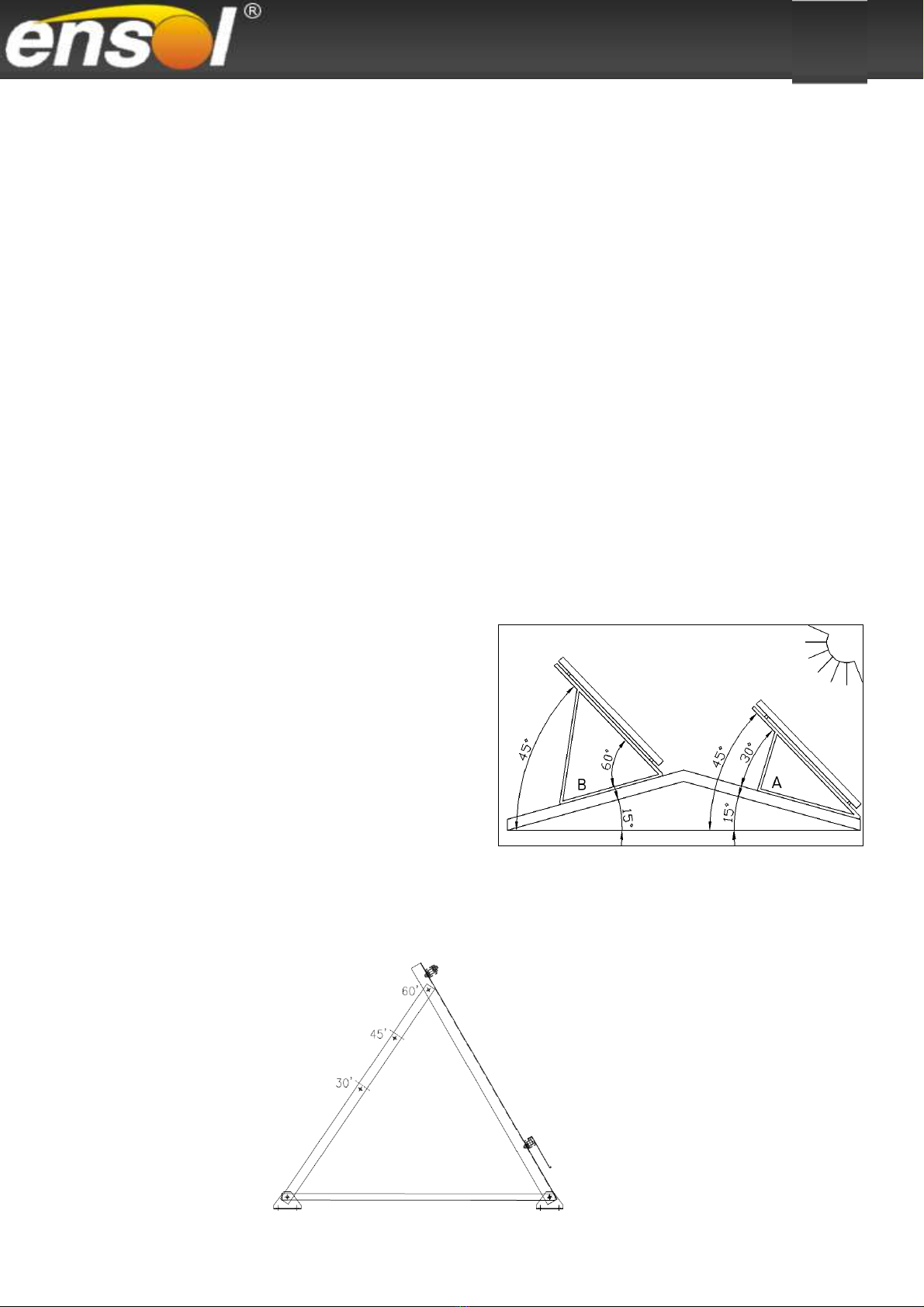
4.1.2 Roof or surface of inclination angle up to 20°
In case of roofs inclined in the
southern direction „A” the roof
inclination should be deducted from
the assumed collector inclination. In
case of roofs inclined in the northern
direction „B”, the roof inclination
should be added to the assumed
collector inclination.
The obtained value indicates the
inclination angle of the set.
4.2 etting the inclination angle
4.2.1 etting the inclination angle of an installation set for a horizontal collector
17
Installation
i
nstruction
for flat collectors on flat roof or foundation.
Inclination angle of an installation set can be adjusted by cutting the profile in a proper,
marked spot. Standard angles of inclination were set at 30, 45 and 60°.
When it is necessary to set the installation set in a different angle one should make
connection holes oneself, bearing in mind the maximum setting of the solar collector angle
in the range of 15 - 60°.
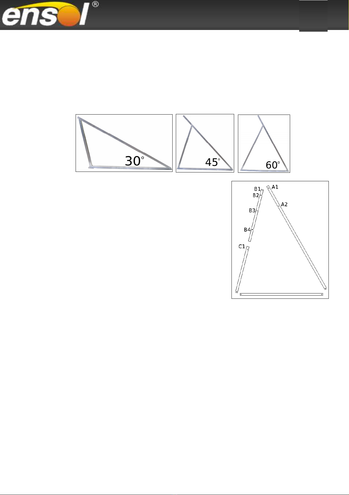
4.2.2 etting the inclination angle of an installation set for a vertical collector
Inclination angle of an installation set can be adjusted
by means of telescopic rails. Standard inclination
angles have been determined as 30, 45 and 60°
depending on the position of the installation set. In
order to obtain the assumed inclination angle, it is
necessary to connect properly the sections of the
installation set.
30
o
angle is obtained by connecting the holes:
A1 with B1 and B2 with C1.
45
o
angle is obtained by connecting the holes:
A2 with B1 and B3 with C1.
60
o
angle is obtained by connecting the holes:
A2 with B1 and B4 with C1.
where:
A – Prop of supporting frame
B – Top strut
C – Bottom strut
When it is necessary to position the installation setat a different angle, connection holes
should be made by oneself, bearing in mind the maximum setting of the solar collector
angle in the range of 15 - 75°.
4.2.3. Inclination angle for n installation set for flat collectors on an economical triangle
(light version)
The construction allows setting the inclination angle only at 45
o
.

18
Installation
i
nstruction
for flat collectors on flat roof or foundation.
4.3 The installation set construction on a flat roof or a foundation

19
Installation
i
nstruction
for flat collectors on flat roof or foundation.
4.4 The assembly of supporting triangles
4.4.1 The assembly of supporting triangles for vertical collectors
The supporting triangles are the base of the installation set. All of the triangles are
assembled in the same manner.
Note!
Before a supporting triangle assembly all of the components should be laid out
according to the figure presented below.
When of all the components are arranged, the assembly triangle can be bolted together,
bearing in mind the setting of a suitable inclination angle (4.2 Determining the inclination
angle of the collectors).

20
Installation
i
nstruction
for flat collectors on flat roof or foundation.
4.4.2 The assembly of supporting triangles for a horizontal collector
The supporting triangles are the base of the installation set. All of the triangles are
assembled in the same manner.
4.4.3 The assembly of supporting triangles and struts – light version (economical)
The supporting triangles are the base for an installation set . All of the triangles are
assembled in the same manner. The installation distance between each triangle should be set
accordingly with the dimensions shown in the figure.
The struts are bolted to the assembled triangles (ADDITIONAL OPTION).
Note!
Before a supporting triangle assembly all of the components should be laid out according to
the figure presented below.
This manual suits for next models
10
Table of contents
Other ensol Solar Panel manuals

Popular Solar Panel manuals by other brands


REC
REC TwinPeak 2S Mono 72 Series installation instructions

Flexsolar
Flexsolar C100 Instruction manual & warranty

Energizer
Energizer HardCase Sunpack 120W user guide

solarwatt
solarwatt EasyIn 60M Series installation instructions

Mission Solar Energy
Mission Solar Energy MONO Series Installation and user manual

Wiedenmann
Wiedenmann Favorit XP Translation of original operating instructions