CR8 MANUAL MULTI-TURN VALVE
3Entegris, Inc. | P/N 01-1011423 | Rev. C 09/18
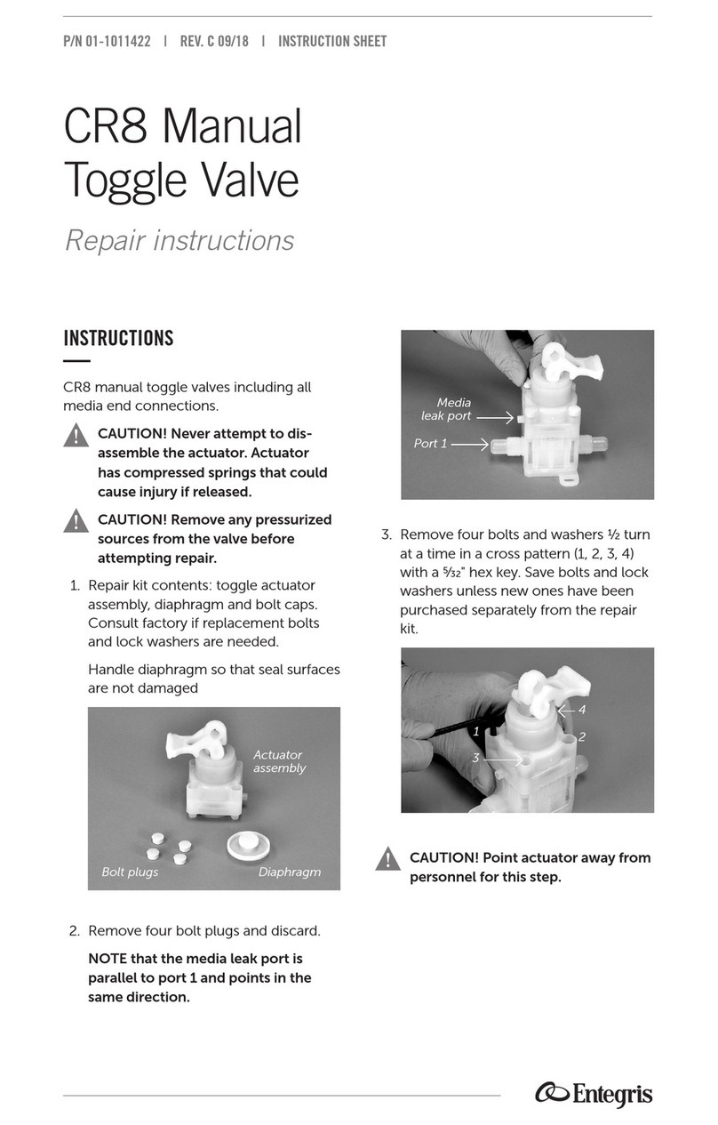
9. Install four bolts and lock washers into
the holes in the actuator assembly.
CAUTION! It is very important to
perform step 10 exactly as directed.
10. Tighten with a torque wrench to
0.11 N•m (1 in•lb) torque in a cross
pattern (1, 2, 3, 4). Repeat this step
in 0.11 N•m (1 in•lb) increments until
1.02 N•m (9 in•lb) torque is reached.
11. A recommended (but not required)
step is to visually check the gap
between the body and actuator. It
should measure less than 1.1 mm
(0.045") and not vary by more than
0.38 mm (0.015"). Use a feeler gauge
or caliper to measure the gap at the
corners of the valve.
12. Turn actuator nut clockwise to
0.56 N•m (5 in•lb) with a ⁄" deep
well socket.
13. Install red stop nut by turning it
clockwise by hand until it stops. Turn
stop nut counterclockwise ⁄–⁄ turns
and align corners of the stop nut and
actuator nut as shown.
14. Install the handle temporarily upside
down as shown. Turn the handle
clockwise with a comfortable finger
tight torque.
1
24
3
Red stop nut
Actuator nut

