ON Semiconductor LV8548MCSLDGEVB User manual

© Semiconductor Components Industries, LLC, 2015 1
2 April 2018- Rev 1.0
.
LV8548MCSLDGEVB
Brush DC Motor Driver Module Solution Kit
Quick Start Guide
Overview
The LV8548MCSLDGEVB is an ON Semiconductor motor driver
module featuring the LV8548MC. This module is capable of easily
driving 2 brushed DC motors.
Motor driving is made easy with Arduino Micro1) compatibility. The
LV8548MCSLDGEVB comes with a Baseboard for facilitated
plug-and-play connectivity with an Arduino Micro. GUI and
Open-source API Functions are available for custom, user-specific
motor driving programs.
Features:
•VCCmax = 20 V, IOmax =1.0 A2)(Through OUT_A-B and OUT_C-D)
• 6~12 V System Applications Recommended(VCC = 4~16V Max)
• Standby current consumption = 0
•Pulse Width Modulation (PWM) control, adjustable motor torque and
speed
•Forward rotation, reverse rotation, and built in brake function
•Typical Applications: In-Home Appliances, Consumer Products,
Industrial Products
For further product information, please visit:
http://www.onsemi.com/PowerSolutions/product.do?id=LV8548MC
What you need
•PC (Windows 7, 64bit)
Arduino IDE 1.8.4 3) Installed
User with an Administrator permission
• Power Supply
AC Adapter Output voltage:4~16V
Output current:~2A
Connector specification
Polarization:Positive Center
Inner diameter=2.1mm、outer diameter=5.5mm
Recommended : WSU075-1000(Triad Magnetics)
or stabilized DC power supply, dry cell battery, etc.
www.onsemi.com
LV8548MCSLDGEVB Board
ONBB4AMGEVB Board with
Arduino Micro and
LV8548MCSLDGEVB Board
1) Arduino / Genuino is Arduino AG are registered trademarks.
2) Stress exceeding this voltage or current may risk damage to the device. Functionality and reliability may be hindered if the device exceeds
these values. The maximum current value, IOmax, does not guarantee the module can handle that much current. If the device
overheats, thermal shutdown will occur.
3) Contents of kit may not be compatible with different versions. Please see the Appendix attached if specified version is not installed.

LV8548MCSLDGEVB for Brush DC motor
www.onsemi.com
2
Contents of the Kit
Hardware
• LV8548MCSLDGEVB:Motor driver module
• ONBB4AMGEVB:Baseboard
•Arduino Micro
•USB Cable (Micro B-A)
•USB Thumb Drive
• Flat-tip Screw Driver
•Brush DC Motor - RC-260RA-18130 (MABUCHI motor) 1pc
(Stepper motor 1pc)
Software(Included in USB Thumb Drive)
Software Setup
Please download
found on the provided USB flash drive to any
preferred directory.
(E.g. Libraries\Documents or Desktop)
API Library
Following process should be operated with the
Arduino Micro disconnected.
①Double click on the Arduino sketch
.
This will launch the Arduino IDE.
(Check the Appendix if the Arduino IDE is not
installed)
The IDE will display the following message when
the LV8548_DC_Program.ino file is opened for the
first time. Click “OK” to continue.
This message will be displayed if the .ino file is not
inside of a folder with the same name. (E.g.
Sketch12345.ino must be in the Sketch12345
folder).
・・・GUI as well as .NET Framework4.6.1 Installer
・・・Arduino IDE Installer
・・・API Library
・・・Instructions for operation and setup (This document)
・・・GUI –Arduino Firmware
・・・Stepper Motor Files
(Refer to Stepper Motor Manual)
・・・Appendix for supplementarymaterial
・・・.NET Framework Related Files
・・・GUI Related Files
・・・Installer package in Japanese

LV8548MCSLDGEVB for Brush DC motor
www.onsemi.com
3
②Include the API Library
As shown below, navigate to Sketch→Include
Library→Add .Zip Library
The following window will appear. Select the
“LV8548_DC_APILibrary” folder, and open this
folder as shown below.
Click the folder only once and push “Open” button.
Do not double click the folder.
Unless updating the function library, including the
API function library only needs to be done once.
Writing and Compiling with the Arduino IDE
①Select the Arduino board to upload to by
navigating to
“Tools→Board→Arduino/Genuino Micro”
②Write an Arduino sketch and navigate to
“Sketch→Verify/Compile” when finished
writing
The IDE will display “Done compiling” after a
successful compile has been verified.
③Connect the PC to the Arduino Micro via
USB and select the corresponding COM port
④Upload the sketch byclicking “Sketch→Upload”
or by pressing the ○
→button
The IDE will display “Done uploading” after a
successful upload to the Arduino
Sketches written to the Arduino will not be erased
unless rewritten.

LV8548MCSLDGEVB for Brush DC motor
www.onsemi.com
4
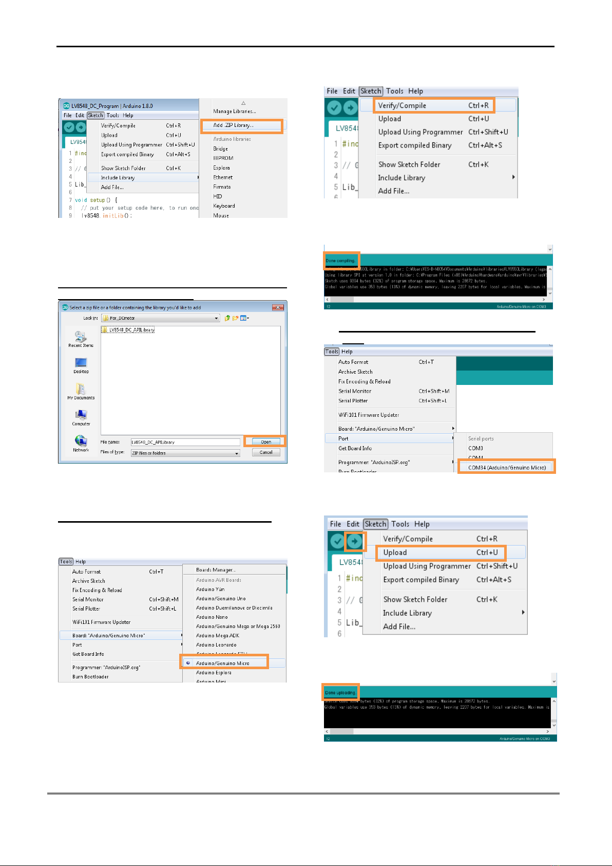
If the uploading of the program fails confirm the
details in step ①check board name and step ③
check serial port connection.
Rewrite the Arduino Program
In the case of ①or ②below, please rewrite the
program to the Arduino
①When updating the API Function library
1)Delete the existing API function library by
navigating to Documents\Arduino\libraries
and deleting the LV8548_DC_APILibrary
folder.
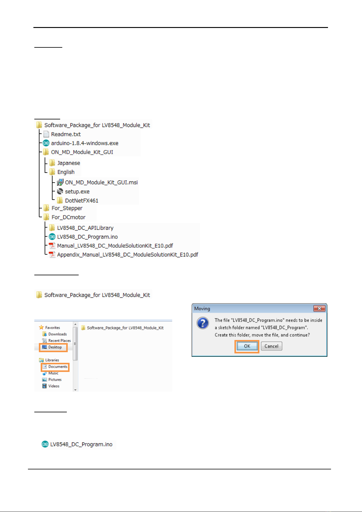
2)Include the latest API function library.
Please save the latest API function library
in your preferred directory on your PC.
(See Page 2, “Software Setup”)
Include the latest API function library.
(See Page 2 “API Library”)
3) Compile and write the program to the
Arduino
(See Page 3, “Writing and Compiling with
the Arduino IDE”)
②Whenevaluating the LV8548 Stepper and other
motor driver modules
(Assuming other motor driver module libraries
have already been included)
1) Compile and write the program to the
Arduino
(See Page 3, “Writing and Compiling with
the Arduino IDE”)
If you are testing the LV8548 Stepper module
library or any other motor driver module library
for the first time, please operate according to
their corresponding manual.
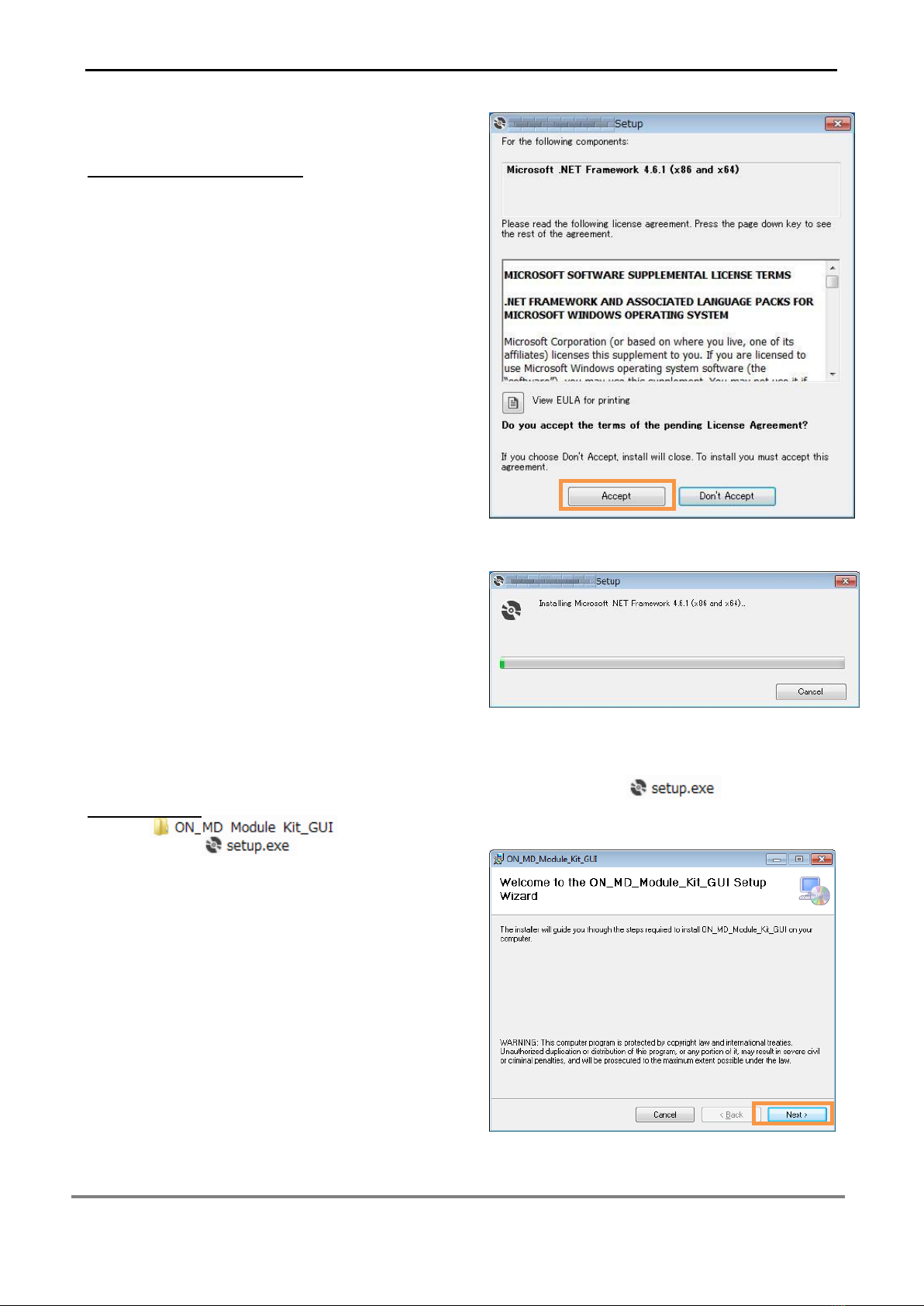
GUI Installation
①In the folder, double
click and run installation file.
*If a previous version of ON_MD_Module_Kit_GUI
has already been installed, please uninstall and
reinstall the GUI
②If .NET Framework4.6.1 is not installed, click
Accept to install.
The following window shows the installation in
progress. (This may take several minutes)
If the installation requires a reboot to complete, a
message will appear on the screen. Please press
“Yes” to reboot.
Once rebooted, run installation file
again.
③Press “Next”

LV8548MCSLDGEVB for Brush DC motor
www.onsemi.com
5
④Specify installation folder, or just click “next” to
continue with the installation
Please press “next”.
If a User Account Control dialog box appears,
please select “Yes.”
The following screen will be displayed after a
successful installation.
Make sure the GUI shortcut icon is created on the
desktop as shown below and that the program has
been added to the Windows start menu.
Start Menu
Desktop Shortcut

LV8548MCSLDGEVB for Brush DC motor
www.onsemi.com
6
Hardware Setup
①Connect the LV8548MCSLDGEVB(Motor Driver Module)to the ONBB4AMGEVB(Motor Driver
Baseboard). Insert the module into the baseboard, while being careful not to bend the header pins
②Connect the Arduino/Genuino Micro to the baseboard, as seen in the figure below. The USB connection
port should be labeled on the baseboard ”USB” to dictate the orientation of the Arduino
③Plug in the motor wires (Insulation between 5mm –10mm) into the output terminals on the baseboard –
OUT_A/B/C/D. Refer to the table below for motor connectivity:
OUT_A
Motor1+
OUT_B
Motor1-
OUT_C
Motor2+
OUT_D
Motor2-
(Double check the motor wires, + and -, to ensure correct rotation direction)
④Connect the Arduino to a PC using a USB cable.
⑤Insert the AC Power adapter into the DC Jack on the baseboard. Be sure that a Center positive type
adapter is being used with an output voltage of 4-16V.
If using power supply cables, please connect the positive terminal to VCC and the negative terminal to
GND in the CN6 connector. The power supply terminals +/- at CN6 are polarity sensitive.(VCC=+,
GND=-)
How to use the GUI
CN6
CN5
③
⑤
④
②
①

LV8548MCSLDGEVB for Brush DC motor
www.onsemi.com
7
①Double-click the GUI shortcut and connect the
COM serial port.
Available COM ports will appear in the drop-down
box.
If the Arduino is connected correctly to the PC, an
option for “Arduino Micro (COMx)” will be available
(where x is the number associated with the port);
select that COM port and click “Connect”.
②The GUI will automatically navigate to the
LV8548DC tab after the Arduino installed the
firmware is connected.
③Specify the desired frequency for PWM
④Set the PWM mode for each motor (Ch1 &
Ch2)
If the motor is running, it is recommended to
press the “Brake” or “Open” button before
switching the direction of rotation.
Please see the Appendix for characteristics
regarding the PWM frequency and PWM
mode.
⑤Change the On Duty ratio for each motor
(10-20% is recommended)
⑥Press the “Start” button to begin motor function
①
②
③
④
⑦
⑧
⑩
⑨
⑩
⑤
⑥
⑪
⑬
⑫

LV8548MCSLDGEVB for Brush DC motor
www.onsemi.com
8
Adjusting the duty ratio while the motors are
rotating is recommended
Be sure to adjust the duty ratio gradually. For
safety reasons, please initiate the motors at a
lower duty ratio and increase gradually.
The Brake function sets the potential at both
leads of the motor to ground and instantly
stops the motor.
The Open function sets both leads of the motor
to an open circuit, which decelerates the motor
to a complete stop.
For additional details, please see the attached
Appendix.
For more details on the following features, please
refer to the attached Appendix:
⑦GUI Language configuration
⑧GUI Tool Tip display
⑨Help function
⑩Closing the GUI
When finished, exit the GUI by pressing the “Exit”
button at the bottom right of the screen or by
clicking “Exit” item at the top menu bar.
The following popup message will be displayed
when exiting the GUI.
Select “Yes” to quit the GUI.
Select “No” to cancel the exit and return to the main
screen.
If the GUI is closed while the motor is still running,
the motor will be stopped and the window will
close.
For more details on the following features, refer to
the next section on How to use the GUI Log:
⑪Saving the GUI log
⑫Clear the GUI log
⑬Program generation

LV8548MCSLDGEVB for Brush DC motor
www.onsemi.com
9
How to use the GUI Log
The log screen in the GUI shows the serial data sent to Arduino to control its API functions.
⑪Saving the GUI Log
By pressing the “SAVE” button, the content displayed on the work log can be saved as a .txt file or a .csv
file.
⑫Clear GUI Log
By pressing the “CLEAR” button, the content displayed on the work log will be erased.
⑬Program Generation
Pressing the “Generate Program” will output the executed API functions on the work log into a .ino
program file that can be uploaded directly with Arduino. By writing the output of the .ino file to Arduino,
motor control can be executed automatically through standalone operation according to the procedure
generated through the GUI Log.
For more details regarding the Arduino program generation function, refer to the attached Appendix under
⑬Arduino Program Automatic Generation.
i. Set Frequency
ii. Set PWM mode
iii. Set Duty Ratio
iv. Toggle Start/Stop
i. Set Frequency
Executed
iii. Set Duty Ratio
Executed
iv. Start/Stop
Executed
ii. Set PWM
Executed
⑪
⑬
⑫
Other ON Semiconductor Control Unit manuals
Popular Control Unit manuals by other brands

Honeywell
Honeywell V4043A manual

Sunx
Sunx SL-VISA instruction manual

Kessel
Kessel Staufix Series Installation and operating instructions

Innodisk
Innodisk EGSS-32R1 manual

Heritage Bathrooms
Heritage Bathrooms SGRC02 Installation instructions and user guide

National Instruments
National Instruments FlexRIO PXIe-79 R Series installation guide

Gasboy
Gasboy 52 Installation & parts manual

Grant
Grant GEO360 Installation & user's instructions

HYDAC International
HYDAC International C4WERE 6 instruction manual

Cooper Menvier
Cooper Menvier Scantronic 9651 user guide

Honeywell
Honeywell W7212 Product data

Continental Refrigerator
Continental Refrigerator FE4CNX210 Manual and user guide