entegris NT 6300 User manual
NT™Proportional
Control Valve,
Model 6300
User Guide
P/N 1365 | REV. C 09/20

1Entegris, Inc. | User Guide
Table of Contents
Introduction ................................... 2
Principle of Operation .............. 2
Factory Configured ................... 2
General Considerations .............. 2
Line Pressure .............................. 2
Dimensions ................................. 3
Installation ..................................... 7
Provided Equipment ................. 7
Mounting Requirements .......... 7
Mechanical Installation ............... 8
Power Supply Requirements ... 8
Electrical Connections ............. 9
Wiring Diagram ........................ 11
Unit Operation ............................ 12
Performance ............................. 12
Operating Environment ......... 13
Operation and Use
Recommendations .................. 14
Performance ............................. 15
Operational Reliability ............ 15
Diagnostic Guide ........................ 16
Maintenance ................................ 17
Normal Operation ................... 17
Valve Homing Function ......... 17
Reference ..................................... 18
Physical Specifications ........... 18
Electrical Specifications ......... 18
Ordering Information ................ 19
Certifications ............................... 20
CE Certification ....................... 20
Repair and Warranty Service .... 20
Technical Support ...................... 20
Warranty ....................................... 21
Terms and Conditions ............... 21
For More Information ................ 21
NT PROPORTIONAL CONTROL VALVE, MODEL 6300

NT PROPORTIONAL CONTROL VALVE, MODEL 6300
2User Guide | Entegris, Inc.
Introduction
This manual is for use with a standard
NT™Proportional Control Valve,
Model 6300. These instruments have
been designed for use in high-purity
fluid applications within industries
that need tightly controlled chemical
processes such as the semiconduc-
tor, biomedical and solar cell
industries. The wetted parts are
constructed with PTFE, PFA or other
similar high-purity inert materials.
WARNING! Attempting to install or
operate standard NT Proportional
Control Valves without reviewing
the instructions contained in this
manual could result in personal
injury or equipment damage.
PRINCIPLE OF OPERATION
—
The user provides a setpoint signal
that corresponds to the desired valve
position. The range code of the
product specifies the maximum CV
of the unit. The setpoint signal will
proportionally control the unit’s CV
from 0 to maximum CV. The CVcurve
is linear.
For example, 6300-CV3-F04-B06-M
has a CVof 1.0 and has a setpoint of
0–5 VDC. A 2.5 VDC setpoint signal
will adjust the valve to a 0.5 CV. A 3.75
VDC setpoint signal will adjust the
valve to a 0.75 CV.
FACTORY CONFIGURED
—
The standard NT Proportional Control
Valve is pre-configured from the
factory for the CVrange chosen by
the user. The specified CVrange is
found on the label of the unit.
NOTE: The NT Proportional Control
Valve has been factory sealed. DO NOT
attempt to remove the cover of the unit.
Any attempt at removal of the unit cover
will void the warranty.
General
Considerations
LINE PRESSURE
—
The system line pressure (measured
at the inlet of the unit) can be
-100 to 415 kPa (-14.5 to 60 psig)
for CV1 – CV4 range. For CV7 – CV 8,
the system line pressure can be
-100 to 550 kPa (-14.5 to 80 psig).
NT PROPORTIONAL CONTROL VALVE, MODEL 6300
3Entegris, Inc. | User Guide
DIMENSIONS
—
The following fitting size and flow
range combinations are available:
Please consult the factory for
custom fitting size and flow range
combinations.
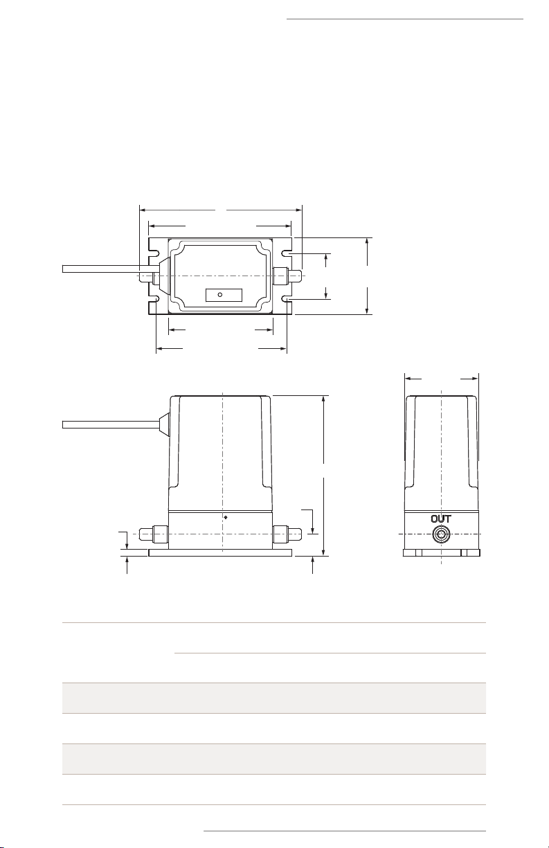
Figure 1. C
V1 – C
V4 ranges
Inlet/outlet
port connection
CV1 – CV4 ranges
Dimensions
ABC
⁄” Flaretek 142.2 mm (5.60”) 144.0 mm (5.67”) 19.5 mm (0.77”)
⁄” Flaretek 142.2 mm (5.60”) 144.0 mm (5.67”) 19.5 mm (0.77”)
⁄” Flaretek 144.5 mm (5.69”) 150.0 mm (5.91”) 21.6 mm (0.85”)
⁄” Flaretek 153.6 mm (6.05”) 153.7 mm (6.05”) 27.4 mm (1.07”)
127.0 mm (5.0”)
92.2 mm (3.63”)
114.0 mm (4.49”)
Side View
Top View
End View
6.4 mm
(0.25”)
C
A
65.5 mm
(2.58”)
68.1 mm
(2.68”)
40.1 mm
(1.58”)
B
Cv1 – Cv4 Ranges
NT PROPORTIONAL CONTROL VALVE, MODEL 6300
4User Guide | Entegris, Inc.
127.0 mm (5.0”)
92.2 mm (3.63”)
114.0 mm (4.49”)
Side View
Top View
End View
6.4 mm
(0.25”)
C
A
65.5 mm
(2.58”)
68.1 mm
(2.68”)
40.1 mm
(1.58”)
B
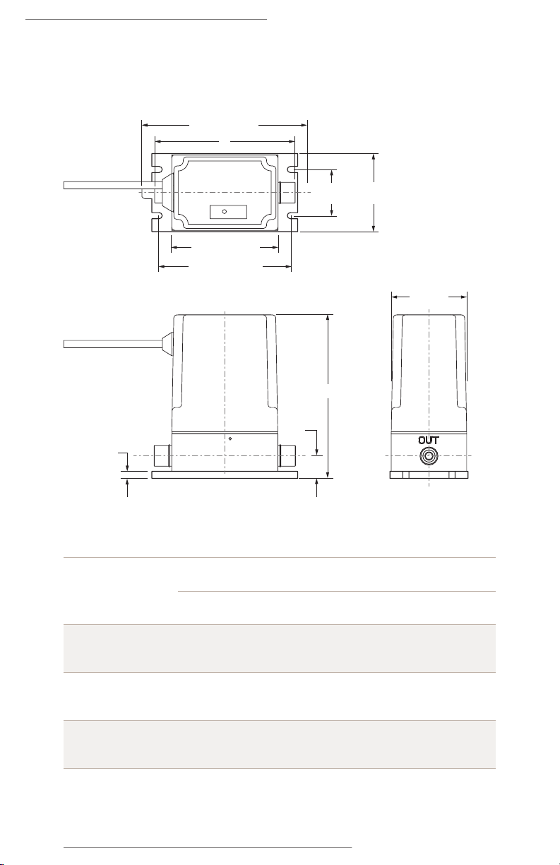
Figure 2. CV1 – CV4 ranges
Cv1 – Cv4 Ranges
Inlet/outlet
port connection
CV1 – CV4 ranges
Dimensions
ABC
⁄” Super 300
Type Pillar 142.2 mm (5.60”) 114.3 mm (4.50”) 19.5 mm (0.77”)
⁄” Super 300
Type Pillar 144.5 mm (5.69”) 127.0 mm (5.00”) 21.6 mm (0.85”)
⁄” Super 300
Type Pillar 153.6 mm (6.05”) 136.1 mm (5.36”) 27.4 mm (1.07”)

NT PROPORTIONAL CONTROL VALVE, MODEL 6300
5Entegris, Inc. | User Guide
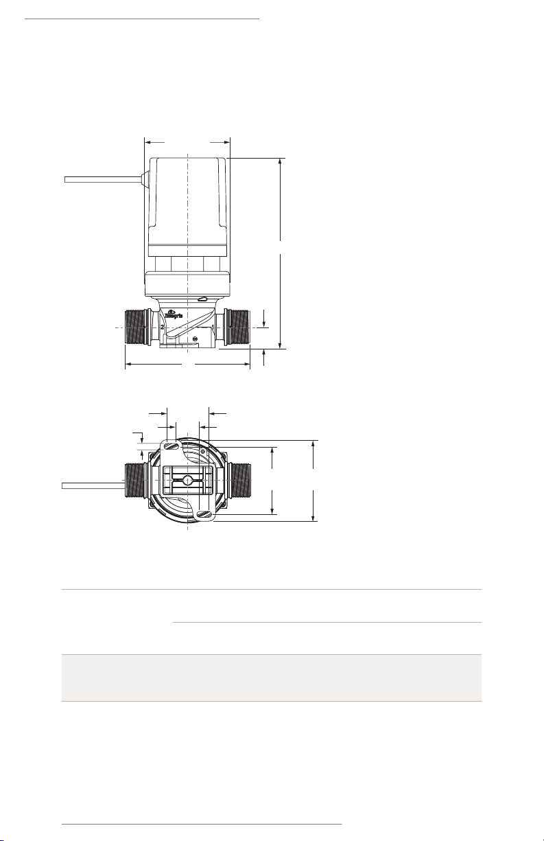
Figure 3. CV7 – CV8 ranges
Cv7 – Cv8 Ranges
(⁄” and 1” Flaretek Inlet/Outlet Type)
Ø99.8 mm
(3.93”)
Side View
Bottom View
A
C
B
49.0 mm
(1.93”)
6.9 mm
(0.27”)
27.9 mm
(1.10”)
79.2 mm
(3.12”)
95.3 mm
(3.75”)
Inlet/outlet
port connection
CV7 – CV8 ranges
Dimensions
ABC
⁄” Flaretek 223.4 mm (8.79”) 129.0 mm (5.08”) 24.4 mm (0.96”)
1” Flaretek 223.4 mm (8.79”) 133.6 mm (5.26”) 24.4 mm (0.96”)
NT PROPORTIONAL CONTROL VALVE, MODEL 6300
6User Guide | Entegris, Inc.
Figure 4. CV8 range
Cv8 Range
(1” Super 300 Type Pillar Inlet/Outlet Type)
Ø99.8 mm
(3.93”)
Side View
Bottom View
49.0 mm
(1.93”)
6.9 mm
(0.27”)
27.9 mm
(1.10”)
79.2 mm
(3.12”)
95.3 mm
(3.75”)
A
B
C
Inlet/outlet
port connection
CV8 range
Dimensions
ABC
1” Super 300
Type Pillar
225.7 mm (8.88”) 146.3 mm (5.76”) 26.7 mm (1.05”)

NT PROPORTIONAL CONTROL VALVE, MODEL 6300
7Entegris, Inc. | User Guide
Installation
PROVIDED EQUIPMENT
—
The product box contains the pro-
portional control valve. For units with
Flaretek connections, two nuts are
included. For units with Pillar connec-
tions, two nuts, two sleeves and two
gauge rings are included.
NOTE: This unit has been assembled
and double-bagged under cleanroom
conditions. To maintain purity, only
open in cleanroom environment.
MOUNTING REQUIREMENTS
—
The proportional control valve may
be mounted in any orientation.
Care should be taken when installing
the proportional control valve to
avoid fluid leaks. Do not use exces-
sive torque or subject the unit to
high heat during installation. The
unit and base bracket assembly must
be mounted to a solid surface to
ensure stability.
Verify the body and the electrical
cable are free from mechanical stress
from the surrounding equipment.
NOTE: The proportional control valve
requires mounting in the direction of
the fluid flow.
#10 (M4)
Pan head
#10 (M4)
Flat washer
Recommended Hardware:
Cv1 – 4
SAE #10 (metric M4)
Cv7 – 8
SAE ¼” (metric M6)
1⁄4”(M6)
Pan head
1⁄4”(M6)
Flat washer

NT PROPORTIONAL CONTROL VALVE, MODEL 6300
8User Guide | Entegris, Inc.
Mechanical
Installation
Prepare and Connect Fluid Lines
The standard NT proportional control
valve must be used with the proper
tubing size and fittings.
CAUTION: Do not tighten the nuts
on the fitting connection without
tubing in place. Tightening the
nuts without the tubing installed
may damage the unit’s
connections.
Flaretek Tube Fitting:
Flare each tube end prior to instal-
lation onto the valve fitting. For
detailed tube flaring instructions,
see “Flaretek tube fitting flare
and assembly procedures” at
www.entegrisfluidhandling.com
Super 300 Type Pillar Tube Fitting:
Prepare tube end prior to instal-
lation onto the valve fitting.
For detailed instructions,
see assembly procedures at
www.nipponpillar.com
CAUTION: Over-tightening of
the nuts with tubing in place will
result in damage to the fitting.
POWER SUPPLY REQUIREMENTS
—
The power supply range for the
proportional control valve is 24 VDC
±10%. The power supply must be
regulated and provide minimum
1.2 ampere (nominal) continuous
service for each proportional control
valve installed. The power supply
requirements must be met at the wire
connections or connector of the
proportional control valve, not only
at the power supply itself.
The power supply to the unit must
provide clean power and must be
used only to power similar measure-
ment-type devices. The power supply
must not be used to power other
inductive loads, such as motors,
relays, or solenoids. These devices
may produce electrical transients
that may aect unit performance.
An induced power spike, creating
an interruption in power greater
than 10 milliseconds in duration,
may cause the unit to reset. Loss of
power will not cause the loss of any
system parameters. Loss of power
may allow the valve to open due to
applied fluid pressure.
In addition to providing clean power,
the instrumentation signals and
power return lines must not be run
within the same conduit or cable
along with heavy current demands
from motors, charging capacitors
or other inductive loads. This may
cause a voltage change within the
instrumentation signal line, causing
erroneous valve operation.
Input Impedance of the
Voltage Setpoint
The input impedance of the voltage
setpoint is 37 kOhm.
Voltage Drop at the 4 – 20 mA
Setpoint Input
The 4–20 mA input will drop
4.6 V at 20 mA. Input impedance
is 230 ohms.

NT PROPORTIONAL CONTROL VALVE, MODEL 6300
9Entegris, Inc. | User Guide
Reverse Polarity Protection
The proportional control valve is
reverse polarity protected; connect-
ing 24 VDC power to any wire will not
harm the unit. To operate properly,
the polarity must be correct.
Over-voltage on any Wire (DC)
In the event of accidental application
of voltage greater than 24 VDC ±10%,
the proportional control valve will
withstand continuous 30 VDC on any
wire without compromising the unit.
Over-voltage on any Wire (AC)
The proportional control valve is not
designed to withstand the accidental
application of ⁄ VAC to any wire.
Application of AC voltage will damage
the unit.
Short Protection
The proportional control valve will
not be damaged or compromised in
any way if any combinations of wires
are shorted together.
Circuit Protection
Entegris recommends fusing
the input power line to the NT
Proportional Control Valve, Model
6300. Use a 2 Amp rated, time-lag
fuse for the proportional control
valve. Place the fusing on the input
power line to the unit at the equip-
ment electrical enclosure to ensure
that both the wiring to the unit and
the unit itself are protected from any
over-current condition. Best practice
is to locate the fuse away from the
typical liquid exposure or harmful
vapor areas. Locating the fuse within
the electrical enclosure shared by the
power supply enables accessibility for
troubleshooting or replacement.
ELECTRICAL CONNECTIONS
—
Pigtail Electrical Cable
Units specified with a pigtail electrical
connection are manufactured with a
permanently attached cable. Table 1
details the wire connections for the
proportional control valve with a
pigtail electrical cable.
Table 1. Wire connections –
pigtail cable
WIRE
COLOR
MARKER
NO. FUNCTION
Red 2+24 VDC
Black 8Ground
(+24 VDC common)
Violet 6Factory use only –
do not connect
White 7Factory use only –
do not connect
Tan 10 Setpoint, current,
4–20 mA
Gray 12 Setpoint, common
Pink 11 Setpoint, voltage,
0–10 or 0–5 VDC
Green 9Valve home input
Pigtail Cable
NT PROPORTIONAL CONTROL VALVE, MODEL 6300
10 User Guide | Entegris, Inc.
G-Series Electrical Connector
Units specified with a G-Series con-
nector use a Turck®brand, versafast
style, BSMK type, constructed of
polyurethane with a nylon coupling
nut. The connector is over-molded
onto an electrically shielded, PVC
jacketed cable. The pin contacts
for the electrical connection are
gold-plated for performance and
corrosion resistance. The connector
is physically “keyed,” making it easy
to connect to a receptacle. Press it
into a receptacle and turn the thread-
ed coupling nut to draw the connec-
tor and receptacle together until
finger tight. G-series connectors to
pigtail mating cables are available.
See the Ordering Information section
of this user guide.
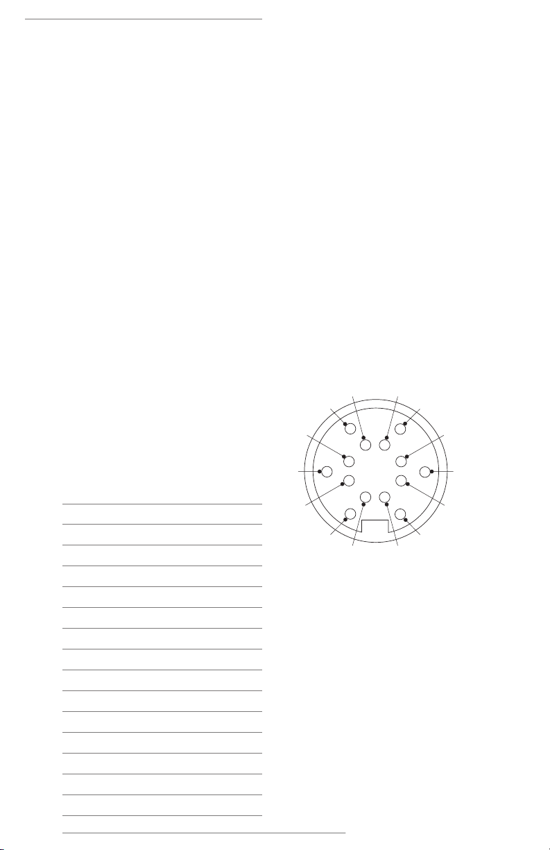
Table 2 and the following pin diagram
detail the wire connections for the
proportional control valve type with
G-series electrical connector.
Table 2. Wire connections –
g-series connector
PIN FUNCTION
R+24 VDC
EGround (+24 VDC common)
JValve home input
USetpoint, current, 4–20 mA
GSetpoint, voltage, 0–10 or 0–5 VDC
SSetpoint, common
OFactory use only – do not connect
PFactory use only – do not connect
MNo connect (NC)
L No connect (NC)
A No connect (NC)
NNo connect (NC)
C No connect (NC)
TNo connect (NC)
Mandatory Connections
Refer to the wire connections in Table
1, Table 2 and the appropriate Wiring
Diagram on page 11.
NOTE: The Valve home input +24 VDC
must be referenced to the same ground
as the main power source ground
2-Black/Pin E connection. See the
Maintenance section of this user guide
for valve homing instructions. Consult
factory with any questions about
electrical installation.
Unused Connections
The 3-Violet/Pin O and 4-White/Pin P
wires are for factory use only. Do not
connect to power supply or ground.
These wires must remain disconnected.
A
E
C
G
J
L
M
N
O
PR
T
U
S
Plug Orientation, Face View

NT PROPORTIONAL CONTROL VALVE, MODEL 6300
11Entegris, Inc. | User Guide
WIRING DIAGRAM
—
For 4–20 mA Setpoint
For Voltage Setpoints
08-Green/Pin J
01-Red/Pin R
(+)
(+)
02-Black/Pin E
06-Gray/Pin S
05-Tan/Pin U
Normally open switch
Power supply
For valve
homing
24 VDC
±10%
Setpoint control signal
4–20 mA
(—)
(—)
Electrical cable
08-Green/Pin J
01-Red/Pin R
02-Black/Pin E
06-Gray/Pin S
07-Pink/Pin G
Electrical cable
Normally open switch
Power supply
For valve
homing
24 VDC
±10%
Setpoint control signal
0–5 VDC
or
0–10 VDC
(+)
(—)
(+)
(—)

NT PROPORTIONAL CONTROL VALVE, MODEL 6300
12 User Guide | Entegris, Inc.
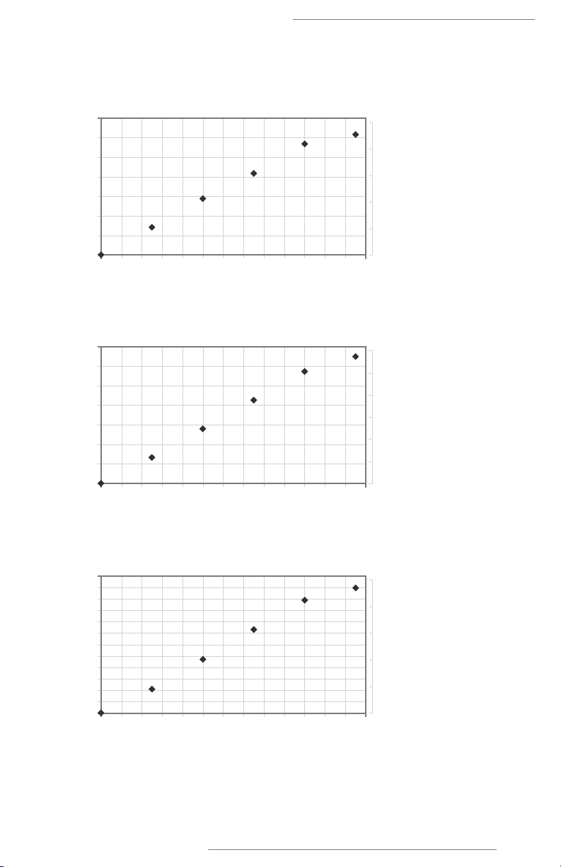
Cv2 F03 (⁄”): Max Cv= 0.68
Cv3 F04/W04 (⁄”): Max Cv= 1.0
Calculated C
v
Cv
Kv
Analog Setpoint Percentage
10 20 30 40 50 60 70 80 90 100 110 120 130
0
0.20
0.18
0.16
0.14
0.12
0.10
0.08
0.06
0.04
0.02
0
0.16
0.14
0.12
0.10
0.08
0.06
0.04
0.02
0
Calculated Cv
Cv
Kv
Analog Setpoint Percentage
10 20 30 40 50 60 70 80 90 100 110 120 130
0
1.2
1.0
0.8
0.6
0.4
0.2
0
1.0
0.8
0.6
0.4
0.2
0
Calculated C
v
Cv
Kv
Analog Setpoint Percentage
10 20 30 40 50 60 70 80 90 100 110 120 130
0
0.9
0.8
0.7
0.6
0.5
0.4
0.3
0.2
0.1
0
0.7
0.6
0.5
0.4
0.3
0.2
0.1
0
Unit Operation
PERFORMANCE*
—
Cv1 F02/ W02 (⁄”): Max Cv= 0.16
NT PROPORTIONAL CONTROL VALVE, MODEL 6300
13Entegris, Inc. | User Guide
Cv4 F06/W06 (⁄”): Max Cv= 2.8
Cv7 F06 Max Cv= 5.6
Cv8 F08/W08 Max Cv= 10.0
*Graph data is representative and each valve needs to be characterized
with the application to optimize performance.
Calculated Cv
C
v
Kv
12.0
11.0
10.0
9.0
8.0
7.0
6.0
5.0
4.0
3.0
2.0
1.0
0
10.0
8.0
6.0
4.0
2.0
0
Analog Setpoint Percentage
10 20 30 40 50 60 70 80 90 100 110 120 130
0
Calculated Cv
C
v
Kv
Analog Setpoint Percentage
10 20 30 40 50 60 70 80 90 100 110 120 130
0
7.0
6.0
5.0
4.0
3.0
2.0
1.0
0
6.0
5.0
4.0
3.0
2.0
1.0
0
Calculated C
v
C
v
Kv
Analog Setpoint Percentage
10 20 30 40 50 60 70 80 90 100 110 120 130
0
3.5
3.0
2.5
2.0
1.5
1.0
0.5
0
2.5
2.0
1.5
1.0
0.5
0
NT PROPORTIONAL CONTROL VALVE, MODEL 6300
14 User Guide | Entegris, Inc.
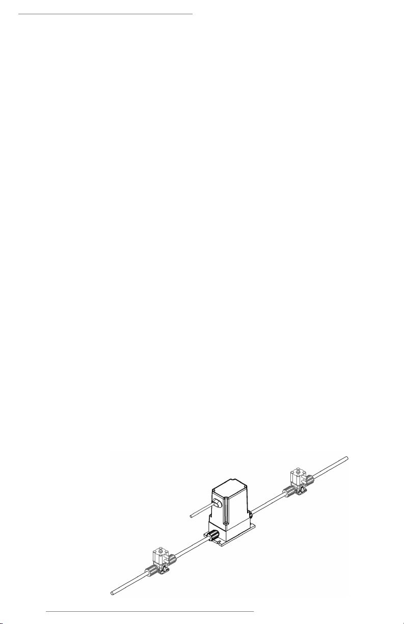
Figure 5. Installation and operation example
with two on/off valves
OPERATING ENVIRONMENT
—
Storage Temperature Range
The proportional control valve can
withstand storage temperatures
between -40° to 65°C (-40° to 149°F)
with no permanent eect on the
performance of the device.
Operating Ambient
Temperature Range
The proportional control valve is
designed to operate in ambient
temperature, cleanroom environ-
ments. Units are specified to oper-
ate at temperatures of 10° to 65°C
(50° to 149°F). For operation above
65°C (149°F), contact the factory.
Operating Process
Temperature Range
Units indicated have a range of
acceptable process temperatures
of 10° to 65°C (50° to 149°F). For
operation above 65°C (149°F),
contact the factory.
Line Pressure
The system line pressure (measured
at the inlet of the unit) can be
-100 to 415 kPa (-14.5 to 60 psig)
for CV1 – CV4 range. For CV7 – CV8
range, the system line pressure can
be -100 to 550 kPa (-14.5 to 80 psig).
Unit Enclosure
The standard NT Proportional Control
Valve cover is factory sealed and
should not be tampered with or
opened. Spray-down or temporary
immersion will not compromise the
performance of the unit.
NOTE: Any attempt to remove, tamper
with or open the proportional control
valve cover will void the warranty.
OPERATION AND USE
RECOMMENDATIONS
—
NOTE: Unit is shipped in an open state.
System Valving Considerations
The NT Proportional Control Valve,
Model 6300 can be installed with
upstream and/or downstream on/o
valves. However, some precautions
should be taken to ensure longevity
and proper operation of the propor-
tional control valve.
The proportional control valve will
close under two conditions:
1. Zero value setpoint
2. Valve Homing signal
command activated

NT PROPORTIONAL CONTROL VALVE, MODEL 6300
15Entegris, Inc. | User Guide
If the proportional control valve closes
while upstream or downstream valves
are closed, this may create a high level
pressure condition in the fluid tubing
due to compressed liquid. This high
pressure condition may lead to
inaccurate homing of the device
(indicated by temporary port-to-port
leaking), a small amount of media
escaping via the weephole, and/or
damage to the device.
To address this issue, one possible
solution is to keep the on/o valves
upstream and downstream of the
proportional control valve open at
all times. If this is not possible, the
proportional control valve should be
closed first, allowing adequate time
before either the upstream or
downstream valves are closed.
Valve Under No-power Condition
The proportional control valve does
not rely on a spring to close. The
motor movement is electrical. Loss
of electrical power will suspend the
valve movement. For example, if the
valve was partially open during loss
of power, the valve will remain par-
tially open. Normal operation will
resume when power is reapplied.
In an unpowered state, the valve
could be forced open with excessive
line pressure.
PERFORMANCE
—
Response Time
Response time is defined as the length
of time required for the proportional
control valve to complete valve move-
ment to match a new setpoint signal.
The maximum response time for
CV1 – 4 is <2 seconds from 5 – 95%
full scale. The maximum response
time for CV7–8, is <4 seconds from
5 – 95% full scale.
The proportional control valve will
accept setpoint changes within 50
milliseconds of receiving the new
setpoint value.
When power is first applied to the
unit (for example, during a startup
sequence), the unit will reach the
correct valve position within ten
seconds.
Temperature Increase at
Unit Enclosure
You may notice a slight temperature
increase of the unit cover while in an
ambient environment after warm-up,
when idling or while controlling flow.
This is normal.
OPERATIONAL RELIABILITY
—
Redundant Process Seals
All internal process wetted seals are
redundant, i.e., there is a secondary
seal that prevents process fluid from
reaching the interior of the device in
the case of a primary seal failure.
Weep holes are provided from the
secondary containment regions.
Drop and Topple
If the unit topples over from a
45-degree angle onto a bench
top, the performance will not be
compromised and the unit will
not be externally damaged.
Cable Pull
The cable will withstand a static pull
test of 9.1 kg (20 lbs.) straight and
4.5 kg (10 lbs.) at 90 degrees without
being damaged.

NT PROPORTIONAL CONTROL VALVE, MODEL 6300
16 User Guide | Entegris, Inc.
Diagnostic Guide
SYMPTOM POSSIBLE CAUSES SUGGESTIONS
1. Unit is
unresponsive
No power Check power connections or fusing.
No setpoint signal Check setpoint wiring for correct setup.
Verify setpoint code of the proportional
control valve matches your wiring setup
and applied setpoint.
Rezero line active Clear rezero line.
2. Unit is unable
to meter flow
Unit is undersized Use a larger CVunit.
Unit is oversized Use a smaller CVunit.
Unstable setpoint signal Check wiring and setpoint electrical
stability.
3. Unit operation
is unstable
Unit installed backwards Verify inlet/outlet connection.
Unstable pressure Check applied pressure stability and/or
stability of downstream backpressure.
Unstable setpoint signal Check wiring and setpoint
electrical stability.
4. Unit causes
high pressure
when closing
External valving Verify the unit does not close against a
fixed volume, trapped between valves
(the proportional control valve can be
one of the two valves).
Stepper motor valve closes and creates
entrapped fluid.
5. Unit does
not close
External valving —
entrapping a fixed volume
Close unit before closing external valve.
See page 14 for more information.
Foreign object in valve Clear obstruction with back flush/
forward flush procedure.
6. Unit leaks
fluid out of
weep hole
Overpressure on unit Intermittent — single overpressure
event. Monitor for future instances.
Continuous — diaphragm rupture.
Call factory for more information.

NT PROPORTIONAL CONTROL VALVE, MODEL 6300
17Entegris, Inc. | User Guide
Maintenance
NORMAL OPERATION
—
During normal operation, the
standard NT Proportional Control
Valve, Model 6300 requires no
maintenance, other than a periodic
valve homing of the unit. In applica-
tions with greater movement duty
cycle, more frequent valve homing
is recommended.
At the time of unit power-up, and
any subsequent power cycle, the
proportional control valve will
perform a valve homing procedure
before becoming active.
VALVE HOMING FUNCTION
—
NOTE: The following procedure
must be followed precisely to ensure
proportional control valve homing.
1. The proportional control valve
homing function requires the
use of the same 24 VDC ±10%
power source that is used to
power the unit.
2. Apply 24 VDC ±10% to the
8-Green/-Pin J wire to initiate
valve homing routine, for a
mini-mum of 1 second. The
24 VDC for valve homing must
use the same ground as the
ground 2-Black/Pin E wire. Only
apply 24 VDC to this 8-Green/-
Pin J wire, long enough to
re-home the valve. The valve
homing will be complete within
5 seconds.
NOTE: The valve homing function will
remain active and at home position as
long as 24 VDC is applied to the valve
home input wire.
In most applications, the valve
homing procedure may be auto-
mated using switches, a PLC or
other logic proportional control
valve devices.
NT PROPORTIONAL CONTROL VALVE, MODEL 6300
18 User Guide | Entegris, Inc.
Reference
PHYSICAL SPECIFICATIONS
—
Materials of
construction
Wetted parts Body and diaphragms PTFE or PFA
Nonwetted parts Polypropylene, Viton®, PVDF
Response time CV1 – CV4<2 seconds from 5 – 95% full scale
CV7 – CV8<4 seconds from 5 – 95% full scale
Pressure range* -14.5 to 60 psig
(CV1 – CV4)
-14.5 to 80 psig
(CV7 – CV8)
Over pressure limit 100 psig
Process temperature** 10° to 65°C (50° to 149°F)
Setpoint input signal 4–20 mA, 0–10 VDC, 0–5 VDC; separate homing line
also included
Enclosure NEMA 5/IP54
Connection type*** Flaretek tube fitting and Pillar Super 300 tube fitting
Approvals
Note: Preliminary specifications and features subject to change.
* Please consult the factory for pressure ranges from 60 to 80 psig.
** Please consult the factory for temperatures from 65° to 80°C (149° to 176°F).
*** For PrimeLock®connections and other options not listed, please contact Entegris.
ELECTRICAL SPECIFICATIONS
—
Input voltage 24 VDC ±10%, regulated
Input current 1.0 A nominal, 1.2 A peak
Impedance of setpoint input (voltage) 37 kOhm
Voltage drop, current setpoint input <4.6 volts @ 20 mA @ 230 ohm
Electrical connection FEP or PVC-jacketed cable

NT PROPORTIONAL CONTROL VALVE, MODEL 6300
19Entegris, Inc. | User Guide
Ordering Information
The model number can be established using the following chart.
NT Proportional Control Valve
6300 Base model
Cv
CV1 0.16 maximum CV(only F02/W02)
CV2 0.68 maximum CV(only F03)
CV3 1.00 maximum CV(only F04/W04)
CV4 2.80 maximum CV(only F06/W06)
CV75.6 maximum CV(available in F06)
CV810.0 maximum CV(available in F08 or W08)
Inlet/OutletType
F02 ⁄”Flaretektubefitting
F03 ⁄”Flaretektubefitting
F04 ⁄”Flaretektubefitting
F06 ⁄”Flaretektubefitting
F08 1” Flaretek tube fitting
W02 ⁄” Super 300 Type Pillar tube fitting
W04 ⁄”Super 300 Type Pillar tube fitting
W06 ⁄”Super 300 Type Pillar tube fitting
W08 1” Super 300 Type Pillar tube fitting
ElectricalConnectorType
B12 FEP-jacketed12’ pigtailelectricalcable
G01 PVC-jacketed 1’ electrical cable terminated with 14-pin Turck connector*
Setpoint Input Signal
K 4–20mA
L 0–10VDC
M 0–5VDC
*14-pin mating cable required for installation
Example model number: 6300-CV1-F02-B12-K
Table of contents
Other entegris Control Unit manuals


